


Tach.Problem!!!
Thread Starter
Safety Car

Joined: Oct 2005
Posts: 3,570
Likes: 1
From: Algonac Michigan
In my boat I have a 350 with a HEI ignition. I installed a new tach and the needle was bouncing all over the place.
Got a different tach. Also new....Same thing
Anyone know what I can do to remove the bouncing needle?? It will finally smooth out at about 3 grand
Is there some kind of filter I can use
C'mon all you electronic engineers....put your thinking caps on....please???
Mark
Got a different tach. Also new....Same thing
Anyone know what I can do to remove the bouncing needle?? It will finally smooth out at about 3 grand
Is there some kind of filter I can use
C'mon all you electronic engineers....put your thinking caps on....please???
Mark
Thread Starter
Safety Car
Joined: Oct 2005
Posts: 3,570
Likes: 1
From: Algonac Michigan
Team Owner

Joined: Aug 2006
Posts: 24,125
Likes: 15
From: Columbia Missouri
I have never bought one, but I'm fairly sure they can be bought at a local parts store. They usually have a foot, that bolts to the manifold acting as a ground, and the wires on each end get spliced so it's inline with the tach wire.
Advanced

Joined: Jun 2004
Posts: 93
Likes: 0
From: Southgate MI
Thread Starter
Safety Car
Joined: Oct 2005
Posts: 3,570
Likes: 1
From: Algonac Michigan
I knew you would be here for me DB, thanks again.
By the way I think I may just get my '69 vert back to get some time in this fall. I'm keeping my fingers crossed ...been gone almost a year for paint.


Mark
By the way I think I may just get my '69 vert back to get some time in this fall. I'm keeping my fingers crossed
...been gone almost a year for paint.Mark
Instructor
Joined: Dec 2005
Posts: 218
Likes: 0
From: Waverly NY
I made my own from schematics in another thread in this forum. You could also buy one. See this thread:
http://forums.corvetteforum.com/showthread.php?t=394449
Kipp
http://forums.corvetteforum.com/showthread.php?t=394449
Kipp

Melting Slicks


Joined: Oct 2002
Posts: 2,317
Likes: 111
From: St Louis MO
In my boat I have a 350 with a HEI ignition. I installed a new tach and the needle was bouncing all over the place.
Got a different tach. Also new....Same thing
Anyone know what I can do to remove the bouncing needle?? It will finally smooth out at about 3 grand
Is there some kind of filter I can use
C'mon all you electronic engineers....put your thinking caps on....please???
Mark
Got a different tach. Also new....Same thing
Anyone know what I can do to remove the bouncing needle?? It will finally smooth out at about 3 grand
Is there some kind of filter I can use
C'mon all you electronic engineers....put your thinking caps on....please???
Mark
After a bit of searching, I found a schematic:
http://forums.corvetteforum.com/show...lter+off+broke, some 5 posts in.
It is a dual RC network in a small can ~ 1 1/4 long by 1/2 inch dia. The can mounts to a bolt on the manifold (ground), one wire goes to the distributor, the other wire from the other end connects to the tach wire which goes to the Tach.
Inside the can, there is a 5.6k resistor which connects to a grounded .10mfd capacitor and also to a 10k resistor, which in turn, connects to a grounded 100pf capacitor and also to the wire output to the tach.
Note that the wire does not connect to ground at all, but passes the signal through the resistors to the tach wire. The capacitors shunt the high frequency noise harmlessly to ground.
This filter allows the low frequency signal (low pass filter) to continue to the tachometer. If the wire from the dist ever did break and short to ground, it would short the C- of the coil to ground, causing the engine to stop, and would do damage to the ignition system fairly quickly.
Corvette Stories
The Best of Corvette for Corvette Enthusiasts

Top 10 Most Expensive Corvettes Ever Sold on Bring A Trailer
Brett Foote
10 Things Every Corvette Owner Needs (2026 Edition)
Michael S. Palmer
8 Most "Only Corvette Owners Understand" Quirks and Problems
Pouria Savadkouei
10 Reasons the C6 Z06 is Still A Performance Benchmark After 20 Years
Joe Kucinski
How Much Horsepower Every Corvette Engine "LOST" in 1972
Joe Kucinski
Top 10 DOs and DON'Ts for Protecting Your Convertible Top!
Michael S. Palmer
Top 10 Most Explosive Corvettes Ever Made: Power-to-Weight Ratio Ranked!
Joe Kucinski
150 hp to 1,250 hp: Every Corvette Generation Compared by the Specs That Matter
Joe Kucinski
8 Coolest Corvette Pace Cars (and Replicas) of All Time
Verdad Gallardo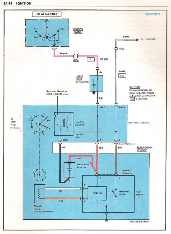
Melting Slicks
Joined: Oct 2002
Posts: 2,317
Likes: 111
From: St Louis MO
I do have this manual, but there NO low pass filter shown between the dist and tach (circuit 121). The radio noise capacitor between the ignition switch and the dist is a different animal, but does function similarly to keep high frequency content out of the power supply lines; however, it is not a low pass RC filter to the tach.
Drifting


Joined: Nov 2003
Posts: 1,634
Likes: 4
From: Northern NJ
St. Jude Donor '04 & '05
The tach filter is located on the drivers side back of the intake manifold as per the circled area below

I doubt the filter is causing your bouncing needle issue, but temporarily bypass it to be sure. (plug the wire from the output side of the filter directly into the distributor) A bouncing needle is usually an issue w/the tach board, but it appears you have already changed that via swapping in a different tach. However did you have a differnet tach board, or did you swap the same board back and forth between the two different tachs?
Good Luck!
Race Director

Joined: May 2006
Posts: 16,528
Likes: 53
From: Dayton, Ohio
I do have this manual, but there NO low pass filter shown between the dist and tach (circuit 121). The radio noise capacitor between the ignition switch and the dist is a different animal, but does function similarly to keep high frequency content out of the power supply lines; however, it is not a low pass RC filter to the tach.
Burning Brakes

Joined: Dec 2007
Posts: 952
Likes: 0
Do you know where the radio noise capacitor shown in the diagram is located on the car? It sure looks like it is the one located on the intake manifold that the tach usually plugs into.Is this diagram a misprint or should the pink power wire be plugged into the cap. mounted on the intake instead of the tach lead???
The cap in the blue area is in the distributor.
The cap shown inline with the red "hot" I have never seen, but may be under the dash.I have never seen anything but the red "keyed on hot" plugged into the HEI cap.
Race Director
Joined: May 2006
Posts: 16,528
Likes: 53
From: Dayton, Ohio
I've been wondering for awhile now if the drawing is correct and we have been plugging the wrong wire into the capacitor on the manifold.All the cars I have seen have the tach plugged into the cap....what if they got it wrong at the factory and it should have been as per the picture?Also the guy that does my gauges has said all along the cap. on the manifold is not good for the tach and that there is a filter already inside the tach head.When I get a tach back from him he insists that the tach be plugged directly into the dist. or the warranty is no good.
Race Director
Joined: May 2006
Posts: 16,528
Likes: 53
From: Dayton, Ohio
Racer

Joined: Jul 2005
Posts: 499
Likes: 1
From: Winnipeg Manitoba
I've been wondering for awhile now if the drawing is correct and we have been plugging the wrong wire into the capacitor on the manifold.All the cars I have seen have the tach plugged into the cap....what if they got it wrong at the factory and it should have been as per the picture?
1) Put in a filter that stops the noise from getting to sensitive devices.
(The RC filter). Works O.K., but it doesn't do anything about the original source of the problem. It tries to reduce the impact of the noise on the system.
2) Put in parts that reduce the amount of noise generated in the first place. The circuit diagram shows the capacitor used as a decoupling capacitor. This provides a local supply of charge for the ignition circuit to pull from. As a result, the peak current pulled down the battery cable is much lower, and so is radiated noise.
No mix up in the diagrams. The Capacitor and the RC tach filter are two different approaches to deal with the same problem.
Racer
Joined: Jul 2005
Posts: 499
Likes: 1
From: Winnipeg Manitoba
Also the guy that does my gauges has said all along the cap. on the manifold is not good for the tach and that there is a filter already inside the tach head.When I get a tach back from him he insists that the tach be plugged directly into the dist. or the warranty is no good.
However, the warranty thing is B.S. The external filter should have no impact on the tach. The purpose of the filters is to reduce the buzz on the radio.
Race Director
Joined: May 2006
Posts: 16,528
Likes: 53
From: Dayton, Ohio