


Gauge testing-thought I would share
Thread Starter
Race Director

Joined: May 2006
Posts: 16,528
Likes: 53
From: Dayton, Ohio
We seem to get into a lot of gauge issues.I've been trying to think up a way of testing that most guys could do at home to establish a standard reading on their gauges.
I have posted the standard GM test before and that is the best place to start.Here it is again and we'll use the temp gauge as an example.
Turn the ignition key on and pull the wire off the temp sender on the engine and watch what the gauge does---gauge should go to or past cold.
Now with key still on ground the same sender wire and watch the gauge---gauge should go to or past hot.
If your gauge does this it usually means the gauge and wiring is in ok shape.
The above 2 tests work on the fuel gauge and the oil pressure gauge also.
Unplugging the wire on the fuel sender at the tank should make the gauge read full.Grounding the fuel sender wire should make the gauge read empty.
Unplugging the wire from the oil sender should make the oil pressure gauge read high pressure.Grounding the oil sender wire should make the gauge read zero.
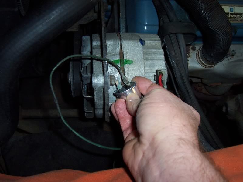
The next test is trying to give a standard to see if the gauge is reading close to correct.Most of the gauges in the car work on 90 ohms.I've been looking for a resistor and decided to check a turn signal flasher and found out of the 3 I had laying around they all read pretty close to 54 ohms.So I hooked up a flasher to each of all 3 gauges on my 78 and took a picture of how the dash gauges read.In the first pic I show how I unplugged the temp sender wire and plugged the wire to 1 of the spades on the flasher and grounded the other spade from the flasher to the alternator belt adjustment bolt.
In the second pic is how each gauge read with the flasher between the wire and ground. (voltmeter not included,and dont try this test on the voltmeter)
You cant get much easier than that.I hope after doing some checking that most peoples flashers will have roughly the same resistance.If there are varying resistances it should be pretty easy to tell what they should read once an ohm meter is used to read the flasher.

Input is welcome and if you could check the resistance on your flasher and try the test and report back it would be great to know if it works for everyone.Thanks
I have posted the standard GM test before and that is the best place to start.Here it is again and we'll use the temp gauge as an example.
Turn the ignition key on and pull the wire off the temp sender on the engine and watch what the gauge does---gauge should go to or past cold.
Now with key still on ground the same sender wire and watch the gauge---gauge should go to or past hot.
If your gauge does this it usually means the gauge and wiring is in ok shape.
The above 2 tests work on the fuel gauge and the oil pressure gauge also.
Unplugging the wire on the fuel sender at the tank should make the gauge read full.Grounding the fuel sender wire should make the gauge read empty.
Unplugging the wire from the oil sender should make the oil pressure gauge read high pressure.Grounding the oil sender wire should make the gauge read zero.
The next test is trying to give a standard to see if the gauge is reading close to correct.Most of the gauges in the car work on 90 ohms.I've been looking for a resistor and decided to check a turn signal flasher and found out of the 3 I had laying around they all read pretty close to 54 ohms.So I hooked up a flasher to each of all 3 gauges on my 78 and took a picture of how the dash gauges read.In the first pic I show how I unplugged the temp sender wire and plugged the wire to 1 of the spades on the flasher and grounded the other spade from the flasher to the alternator belt adjustment bolt.
In the second pic is how each gauge read with the flasher between the wire and ground. (voltmeter not included,and dont try this test on the voltmeter)
You cant get much easier than that.I hope after doing some checking that most peoples flashers will have roughly the same resistance.If there are varying resistances it should be pretty easy to tell what they should read once an ohm meter is used to read the flasher.
Input is welcome and if you could check the resistance on your flasher and try the test and report back it would be great to know if it works for everyone.Thanks
Former Vendor
Joined: Aug 2006
Posts: 76,656
Likes: 1,853
From: Jeffersonville Indiana 812-288-7103
St. Jude Donor '08-'09-'10-'11-'12-'13-'14-'15
Roger,
Your on the right track, and this is a handy quick no cost check method. The instrument you need to test the gauges with is a variable potentiometer also called an Adjustable POT. You can purchase these pretty cheap at audio stores (Radio Shack).
I was trying to build a new tester the other day and actually had a hard time finding what I wanted, but I improvised! I had an older tester take a dump on me the other day and the potentiometer in it was of the slide type similar to what is used inside a gas tank sending unit. So the older style POT is getting harder to find, you can purchase one that is used in electric guitars and amps. .
The only problem with a style like this is dialing it in. If you purchase one that is a 500 ohm pot which will cover anything automotive, (and it is the size of a quarter), finding 25 or 75 ohms can be tricky since the resistance change is so touchy. But if you find a 100 ohm pot, (the same size) you can put it in a series and make adjustments for the higher readings with a second or third one. Believe me, no one cares when their car is running 100 degrees, so creating a something that is higher than 300 ohms is not needed.
So with this in mind, I pasted this link, but I think your local Radio Shack will have this in 100 ohms too! http://www.allelectronics.com/make-a...TAPER/-/1.html You’ll need three of these to go from 0 – 300.
The temperature gauge should read as follows per the input ohms value.
220 degrees = 70 ohms
200 degrees = 90 ohms
160 degrees = 140 ohms
120 degrees = 250 ohms
100 degrees = 340 ohms
The readings above are per GM. Now your flasher is sending out such a low ohm’s reading that it has pushed it off my scale which would be correct. So I would guess 250 degrees = 54 ohms. (This gauge is not linear so it's hard to tell what reading it is).
On the fuel gauge the input on a car from 1963 to 1982 would be 0 = empty and 90 = full.
Your test for testing the fuel sender is correct in ever detail. Grounding the gauge at the sender will establish if the gauge is working only if the wires to the gauge are intact and not shorted. So if your test at the sender fails, you’ll need to ground out the gauge itself for a quickie test. Or in your case remove the ohms wire from your center plug and with your new tester dial up the ohms needed on a test wire inserted. If the gauge works now, you have established the problem is between the gauge and the sender if the sender in the tank test good.
Testing the ohms output wire at the sender will tell you if the sending unit is working. It takes two people to do this test if you want to do it without removing the sending unit from the car. I’m not sure if you can test a sender in the tank on 78-82 cars, due to the restrictor in place for the unleaded fuel. To test it, put the ohm’s meter on the output wire on the sender while someone raises and lowers the float through the filler neck with a coat hanger. The meter should send out 0 – 90 (sometimes they will go as high as 110).
The oil pressure gauge works on the same principle as the fuel gauge 0 – 90 ohms with 90 ohms = 80 psi. and 45 ohms = 40 psi. (It’s linear).
The amp gauge is a little trickier and I don’t have time to go in to this tonight. I’ll see if I can make a post later this evening or tomorrow.
Tell you what, I have to take a trip out to the electronics shop real soon and if I get there I'll pick a few extra's up and mail them to you. You'll need ***** and a box to put them in but once done you should be able to test any fuel and temp gauge needed.
Last edited by Willcox Corvette; Nov 27, 2008 at 06:08 PM.

Instructor

Joined: Nov 2008
Posts: 106
Likes: 1
That is great information for those of us(me) who don't havea clue where to start getting the gauges working correctly. Hopefully, I will be at that stage about next week after I get this wiring figured out.
Thanks again,
Ray
Thanks again,
Ray
Former Vendor
Joined: Aug 2006
Posts: 76,656
Likes: 1,853
From: Jeffersonville Indiana 812-288-7103
St. Jude Donor '08-'09-'10-'11-'12-'13-'14-'15
This might help some people with Fuel Gauge problems.
Image pulled down, this image was specifically for 63-67 cars and not correct for 68 and newer.
Willcox
Image pulled down, this image was specifically for 63-67 cars and not correct for 68 and newer.
Willcox
Last edited by Willcox Corvette; May 20, 2009 at 07:31 PM.
Former Vendor
Joined: Aug 2006
Posts: 76,656
Likes: 1,853
From: Jeffersonville Indiana 812-288-7103
St. Jude Donor '08-'09-'10-'11-'12-'13-'14-'15
The signal on the tach can be split over and over again on the electronic tachometer.
If you have the tach out of the car and a buddy that will let you hook it up you can hard wire the tach and make adjustments compared to his tach!
If you do this make sure to take the tach all the way out to a point where you can see the board. If you look at the board there is a resistor that controls the needle and you turn it to fine tune.
There was a post on the C1-C2 Section the other day about how to calculate the RPM’s based on the tire size, gear and so on. You might want to search archives for this.
About the only other way is to have a distributor machine and dial it in.
Willcox
Corvette Stories
The Best of Corvette for Corvette Enthusiasts

5 Best & 5 Worst Corvette Daily Drivers
Joe Kucinski
The Headlights of Every Corvette Generation Explained
Joe Kucinski
5 Best & 5 Most Overrated Corvette Track Packages of All Time!
Joe Kucinski
Every 2027 Corvette Engine Explained
Joe Kucinski
Designer Imagines A Corvette That Looks More Like a Corvette Than the Corvette
Verdad Gallardo
10 Ugly Corvettes That We Still Kinda Love
Joe Kucinski
Top 10 Most Expensive Corvettes Ever Sold on Bring A Trailer
Brett Foote
10 Things Every Corvette Owner Needs (2026 Edition)
Michael S. Palmer
8 Most "Only Corvette Owners Understand" Quirks and Problems
Pouria SavadkoueiDrifting


Joined: Mar 2008
Posts: 1,900
Likes: 3
From: Nixa Missouri
Thanks for this information. I know when theres a electrical problem tread that DWncchs and willcox are some of the first to help and I've been wacthing this like a hawk, so I know when I start to get into my electrical portion of my cars I'll know who to look for. Thanks again for the info.

Burning Brakes

Joined: Apr 2008
Posts: 945
Likes: 1
I'm no expert but couldn't you just buy a handful of cheap resistors, pull the wire off the sending unit and hook the wire in series throught the resistor to the block and compare the resistance to the guage reading?
220 degrees = 70 ohms
200 degrees = 90 ohms
160 degrees = 140 ohms
120 degrees = 250 ohms
100 degrees = 340 ohms
220 degrees = 70 ohms
200 degrees = 90 ohms
160 degrees = 140 ohms
120 degrees = 250 ohms
100 degrees = 340 ohms
Instructor
Joined: Oct 2008
Posts: 176
Likes: 1
Radio shack carries resistors in an assortment pretty cheaphttp://www.radioshack.com/product/in...&tab=techSpecs
Thread Starter
Race Director
Joined: May 2006
Posts: 16,528
Likes: 53
From: Dayton, Ohio
(Some have mentioned using a test light with an 1893 bulb,but the bulb is only about 3-4 ohms...that wont work.)

Race Director


Joined: Sep 1999
Posts: 11,361
Likes: 383
From: Plano TX
The tach is harder as it needs pulses to read anything, not resistance. Years ago when I converted my '71 to a 75-77 electric tach I build a test rig to calibrate it. The circuit I built would output an adjustable frequency square-wave signal so I could make the tach read anything I wanted. I then used an oscilloscope to check the frequency and converted the frequency to rpm. I found I could make the tach read correct at either low or high rpm but not both. So I made it read correct at low rpm and know that it will read 300 rpm high at 6000.
Instructor
Joined: Sep 2007
Posts: 198
Likes: 0
From: Colorado Springs Colorado
Thanks zwede,
Thats what I was looking for. Would you still have a diagram of the circuit you built? I've got an oscilloscope, and can convert to RPM, but have no idea about the circuit make-up.
Thats what I was looking for. Would you still have a diagram of the circuit you built? I've got an oscilloscope, and can convert to RPM, but have no idea about the circuit make-up.

Burning Brakes
Joined: Apr 2008
Posts: 945
Likes: 1
Yes....and I have suggested it and even shown this pic(below)but it seems as if no one wants to make the trip to Radio Shack...thats why I decided to try and come up with a way you could use the tools from your garage or parts from your car.The signal or hazard flasher is something all the cars have and if a guy has a multi meter he can just measure the resistance of his flasher and go by the scale you put up and he should be in the ball park as to what his dash gauge should read.In the pic below the dash gauge reading should be about 215 degrees.
(Some have mentioned using a test light with an 1893 bulb,but the bulb is only about 3-4 ohms...that wont work.)
(Some have mentioned using a test light with an 1893 bulb,but the bulb is only about 3-4 ohms...that wont work.)
Race Director
Joined: Sep 1999
Posts: 11,361
Likes: 383
From: Plano TX
Sorry, it was so long ago. The circuit is an astable flip-flop. Maybe you can find a diagram for one online. It can be built with transistors (like I did) or a 555-timer. Either way is simple, just a few components. Or maybe you can find/borrow a frequency generator.
Former Vendor
Joined: Aug 2006
Posts: 76,656
Likes: 1,853
From: Jeffersonville Indiana 812-288-7103
St. Jude Donor '08-'09-'10-'11-'12-'13-'14-'15
I feel like I Hi-jacked DWncchs thread. . .  This was not my intention. I went to much detail, and the initial post was for "how to with what you have".
Willcox Inc.
This was not my intention. I went to much detail, and the initial post was for "how to with what you have". Willcox Inc.