









The last Spal Wiring thread........
Thread Starter
Melting Slicks


Joined: Dec 2003
Posts: 2,487
Likes: 1
From: Sydney
 The last Spal Wiring thread........
Ok I am in the final stages of planning the wiring for my spal thermo fans. I have just spent hours going through all the previous spal threads which all have different info and ideas in them, and also looking at the various components and my car.
So I thought I would list all the different views/opinions in one place so you don't need to go through all 15-20 threads to find the info (like I just did, and I am sure countless others have too).
Ok first off I have the dewitts rad with dual spals and radiator mounted temp sensor (but using an engine mounted temp sensor isn't any different the sensor wire just runs to the engine instead of the rad). I am not using any PWM controller or anything like that just the supplied relays.
FIRST TOPIC: Where to get the main power for the fans (This is the heavy guage wire that runs to the relays)
The four options I have seen listed are:
1) Direct to the battery + terminal
2) To the starter motor
3) To the back of the alt
4) to the horn relay power distribution block (mounted on the drivers side fender near the alternator (it has all the wires running to it)
Of all the threads the only one of these options that no one has had any bad comments about is the horn relay distribution block, this seems to make sense the main power cable from the alternator runs direct to this distribution block and it means the wiring won't look so 'hacked'. This is the option I think I will use.
SECOND TOPIC: Where to mount the Relays
The options I have seen listed (and these seem to vary mainly based on where you get main power for the relays):
1) Passenger side fender (usually used if getting power from the starter motor, or if you have a pass. side mounted alt and get the power from that)
2) Driver side fender (used if getting getting power from the horn relay dist. block or driver side mounted alt)
3) In the cavity where the headlights are (they are more hidden there, but can also be harder to get to, and maybe could get wet easier)
4) Inside cabin of car behind the dash
5) Inside compartment behind passenger seat (used if getting main power direct from battery)
6) Direct to the spal fan shroud (they can be quite visible here depending on how they are mounted)
From these options I decided to make a little mounting plate and attach the two relays using the same bolt that holds the horn relay on the driver side fender, there is enough room to hide them in the fender above the vacuum reservoir (at least there is enough room on my '70, not sure on other models), since I am getting power from horn dist. block I figured that made sense only a short wire is need to get main power.
THIRD TOPIC: Where to get IGN/ACC power from
This is the switched power that only comes on when the car is turned on, this is the small wire that runs to the relay from the ignition.
The options seem to be:
1) ACC or IGN terminal on fuse box, which is mounted just above the pedals inside the car (there is usually an unused ACC terminal, you just need a female connector and away you go)
2) Yellow wire on wiper motor (this seems to be used when people don't want to run a wire through the firewall to fusebox).
3) Wire that goes to electric choke (some tap into this, or some don't have it connected anymore anyway so it is ready to go)
4) Any other switched (either ACC or IGN) wire in the engine bay, you can look at a wiring diagram and pick one and tap into it, but this is a bit more of a 'hack' method)
Since my relays are very close to the factory wiring hole in the firewall I will just run the wire through the firewall and use an unused ACC terminal on my fusebox, this seems to me like the most professional way to do it.
FOURTH TOPIC: How to have fans activated
Having two fans there are a heap of different ways people have wired them to activate, I guess this depends on how you drive the car, how hot your motor gets, what the climate is like etc etc etc
The options I have seen mentioned are:
1) Both fans activated from the temp sensor
2) One fan always on when car is on, One fan activated by temp sensor
3) One fan activated by A/C or manually switched and one fan activated by temp sensor
4) Both fans manually turned on
5) Each fan activated by different temp rated sensors (ie one 195/175 on/off and one 185/165 on/off temp sensor) this method requires two temp sensors mounted somewhere (radiator or engine) and the extra wire from the second sensor.
To start with I am just going to have both fans activated by the temp sensor (but I will install a manual over-ride switch just incase the temp sensor fails, all this involves is installing an earthed switch somewhere in the wire that comes from the temp sensor, if you flick the switch the fans will be turned on permanently irrespective of the temp sensor). I will see how this goes and change if necessary.
If anyone has anything to add, or pics of wiring diagrams to help with my description please do.
Hope this saves some people some time, enjoy
cosmic
So I thought I would list all the different views/opinions in one place so you don't need to go through all 15-20 threads to find the info (like I just did, and I am sure countless others have too).
Ok first off I have the dewitts rad with dual spals and radiator mounted temp sensor (but using an engine mounted temp sensor isn't any different the sensor wire just runs to the engine instead of the rad). I am not using any PWM controller or anything like that just the supplied relays.
FIRST TOPIC: Where to get the main power for the fans (This is the heavy guage wire that runs to the relays)
The four options I have seen listed are:
1) Direct to the battery + terminal
2) To the starter motor
3) To the back of the alt
4) to the horn relay power distribution block (mounted on the drivers side fender near the alternator (it has all the wires running to it)
Of all the threads the only one of these options that no one has had any bad comments about is the horn relay distribution block, this seems to make sense the main power cable from the alternator runs direct to this distribution block and it means the wiring won't look so 'hacked'. This is the option I think I will use.
SECOND TOPIC: Where to mount the Relays
The options I have seen listed (and these seem to vary mainly based on where you get main power for the relays):
1) Passenger side fender (usually used if getting power from the starter motor, or if you have a pass. side mounted alt and get the power from that)
2) Driver side fender (used if getting getting power from the horn relay dist. block or driver side mounted alt)
3) In the cavity where the headlights are (they are more hidden there, but can also be harder to get to, and maybe could get wet easier)
4) Inside cabin of car behind the dash
5) Inside compartment behind passenger seat (used if getting main power direct from battery)
6) Direct to the spal fan shroud (they can be quite visible here depending on how they are mounted)
From these options I decided to make a little mounting plate and attach the two relays using the same bolt that holds the horn relay on the driver side fender, there is enough room to hide them in the fender above the vacuum reservoir (at least there is enough room on my '70, not sure on other models), since I am getting power from horn dist. block I figured that made sense only a short wire is need to get main power.
THIRD TOPIC: Where to get IGN/ACC power from
This is the switched power that only comes on when the car is turned on, this is the small wire that runs to the relay from the ignition.
The options seem to be:
1) ACC or IGN terminal on fuse box, which is mounted just above the pedals inside the car (there is usually an unused ACC terminal, you just need a female connector and away you go)
2) Yellow wire on wiper motor (this seems to be used when people don't want to run a wire through the firewall to fusebox).
3) Wire that goes to electric choke (some tap into this, or some don't have it connected anymore anyway so it is ready to go)
4) Any other switched (either ACC or IGN) wire in the engine bay, you can look at a wiring diagram and pick one and tap into it, but this is a bit more of a 'hack' method)
Since my relays are very close to the factory wiring hole in the firewall I will just run the wire through the firewall and use an unused ACC terminal on my fusebox, this seems to me like the most professional way to do it.
FOURTH TOPIC: How to have fans activated
Having two fans there are a heap of different ways people have wired them to activate, I guess this depends on how you drive the car, how hot your motor gets, what the climate is like etc etc etc
The options I have seen mentioned are:
1) Both fans activated from the temp sensor
2) One fan always on when car is on, One fan activated by temp sensor
3) One fan activated by A/C or manually switched and one fan activated by temp sensor
4) Both fans manually turned on
5) Each fan activated by different temp rated sensors (ie one 195/175 on/off and one 185/165 on/off temp sensor) this method requires two temp sensors mounted somewhere (radiator or engine) and the extra wire from the second sensor.
To start with I am just going to have both fans activated by the temp sensor (but I will install a manual over-ride switch just incase the temp sensor fails, all this involves is installing an earthed switch somewhere in the wire that comes from the temp sensor, if you flick the switch the fans will be turned on permanently irrespective of the temp sensor). I will see how this goes and change if necessary.
If anyone has anything to add, or pics of wiring diagrams to help with my description please do.
Hope this saves some people some time, enjoy
cosmic
Last edited by cosmicvette; Apr 24, 2009 at 11:17 AM.
Le Mans Master


Joined: Jan 2006
Posts: 9,192
Likes: 27
From: Boca Raton Florida
My preference has always been to pick up power from the alternator and leave the stock harness alone.
Either mount the relays on the shroud on the drivers side or on the fender skirt drivers side. Nice and clean and does not look bad.
Run the wire thru the firewall and use the ACC terminal
Set the fans up to come on with the temp sensor and the AC. A manual switch will make you more comfortable but should not be needed. Be sure and run a good ground wire from the fans to the alternator bracket.
Either mount the relays on the shroud on the drivers side or on the fender skirt drivers side. Nice and clean and does not look bad.
Run the wire thru the firewall and use the ACC terminal
Set the fans up to come on with the temp sensor and the AC. A manual switch will make you more comfortable but should not be needed. Be sure and run a good ground wire from the fans to the alternator bracket.
Melting Slicks


Joined: Aug 2006
Posts: 3,429
Likes: 20
From: Kingston Ontario
(but I will install a manual over-ride switch just incase the temp sensor fails,
Glad to see someone is pro-active. It's so easy to do, everybody should consider it. Also, hooking up to the horn relay will not compromise the stock wiring harness, it's just another connector bolted to the relay. Actually you would notice it less than an extra wire coming off the alternator.
Good write up.
Glad to see someone is pro-active. It's so easy to do, everybody should consider it. Also, hooking up to the horn relay will not compromise the stock wiring harness, it's just another connector bolted to the relay. Actually you would notice it less than an extra wire coming off the alternator.
Good write up.
Burning Brakes

Joined: Aug 2007
Posts: 1,173
Likes: 1
From: Liberty Missouri
Nice write up! Thanks for taking the time to put it all together. It would have been nice to have this when I was wiring my fans. The only other thing that might be nice to add is several different wiring diagrams. Still great job!!!
Thread Starter
Melting Slicks
Joined: Dec 2003
Posts: 2,487
Likes: 1
From: Sydney
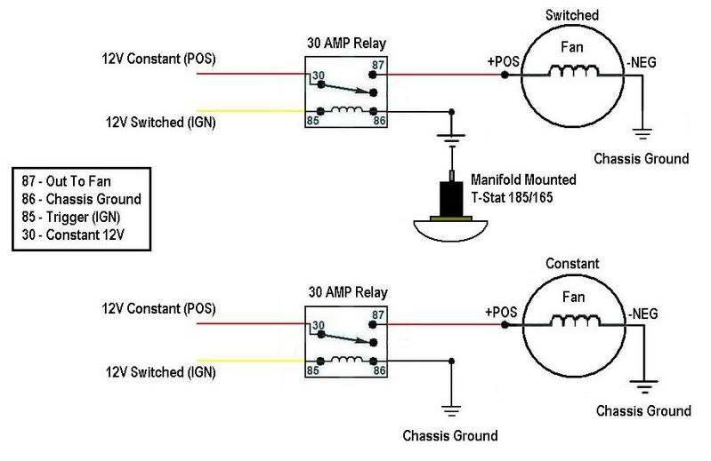
Ok here are all the spal wiring diagrams I could find, unfortunately a lot of the diagrams no longer work (have been deleted from photobucket etc) So if you have any other wiring diagrams to add please do.
Wiring diag from Durango_Boy, one fan switched by temp. sensor, one fan always on (when ign is on):
Wiring diag from Richard454, showing one manual switched relay connected to battery for main power:
Another wiring diag from Richard454, this time showing one relay connected to temp sensor, with manual over-ride. The relay is getting main power from alternator:
Wiring diag from Durango_Boy, one fan switched by temp. sensor, one fan always on (when ign is on):
Wiring diag from Richard454, showing one manual switched relay connected to battery for main power:
Another wiring diag from Richard454, this time showing one relay connected to temp sensor, with manual over-ride. The relay is getting main power from alternator:
Corvette Stories
The Best of Corvette for Corvette Enthusiasts

How Much Horsepower Every Corvette Engine "LOST" in 1972
Joe Kucinski
Top 10 DOs and DON'Ts for Protecting Your Convertible Top!
Michael S. Palmer
Top 10 Most Explosive Corvettes Ever Made: Power-to-Weight Ratio Ranked!
Joe Kucinski
150 hp to 1,250 hp: Every Corvette Generation Compared by the Specs That Matter
Joe Kucinski
8 Coolest Corvette Pace Cars (and Replicas) of All Time
Verdad Gallardo
Top 10 Corvette Engines RANKED by Peak Torque (70+ Years of Muscle!)
Joe Kucinski
Corvette ZR1X Will Be Pacing the Indy 500, And Could Probably Race, Too!
Verdad Gallardo
Top 10 Corvettes Coming to Mecum Indy 2026!
Brett Foote
Top 10 C9 Corvette MUST-HAVES to Fix These C8 Generation Flaws!
Michael S. Palmer
Burning Brakes
Joined: Jul 2006
Posts: 1,047
Likes: 12
From: SoCal
I don't have a diagram, but I use two relays wired in parallel, switched/trigger signal comes from the IGN terminal on the fuse block, main power comes from the stud on the horn relay.
If you want to know why I used two relays wired in parallel, refer to this writeup (see the section titled "for ELECTRIC RADIATOR FAN SYSTEMS", I experienced exactly what this section is talking about when I used only one relay): http://www.madelectrical.com/catalog/rly-1.shtml
If you want to know why I used two relays wired in parallel, refer to this writeup (see the section titled "for ELECTRIC RADIATOR FAN SYSTEMS", I experienced exactly what this section is talking about when I used only one relay): http://www.madelectrical.com/catalog/rly-1.shtml

Former Vendor
Joined: Jan 2000
Posts: 5,593
Likes: 631
From: Brighton
Very nice write up. I will have to save that for reference to others.
One comment on the AC trip and that is I don't care for it. First of all, it requires the use of a third relay harness to make this work. Second, this method loads the electrical system (spike) all at once by triggering both the fans and the AC. Third, you wouldn't want the fans to run when you were doing a highway cruise but you might want the AC.
One comment on the AC trip and that is I don't care for it. First of all, it requires the use of a third relay harness to make this work. Second, this method loads the electrical system (spike) all at once by triggering both the fans and the AC. Third, you wouldn't want the fans to run when you were doing a highway cruise but you might want the AC.

Team Owner


Joined: Jul 1999
Posts: 65,492
Likes: 230
From: Orange Park Florida
Very nice write up. I will have to save that for reference to others.
One comment on the AC trip and that is I don't care for it. First of all, it requires the use of a third relay harness to make this work. Second, this method loads the electrical system (spike) all at once by triggering both the fans and the AC. Third, you wouldn't want the fans to run when you were doing a highway cruise but you might want the AC.
One comment on the AC trip and that is I don't care for it. First of all, it requires the use of a third relay harness to make this work. Second, this method loads the electrical system (spike) all at once by triggering both the fans and the AC. Third, you wouldn't want the fans to run when you were doing a highway cruise but you might want the AC.
IMO, I used a nice heavy relay from some GM install, like would be a high speed blower relay, rated 30 amps + on the contacts...never a issue....so far...

I really don't care for them dime store looking import relays we find in parts houses, and those wiring kits, are abdominable...

Thread Starter
Melting Slicks
Joined: Dec 2003
Posts: 2,487
Likes: 1
From: Sydney
Yeah I wouldn't use A/C trip either (definitely not tripping both fans at once anyway, maybe just one) but I added it there for completeness, plus I am not running A/C so I didn't really give it much thought anyway.
If anyone has any other circuit diagrams to add please do, I know there were a couple of other ones floating around over the last few years.
If anyone has any other circuit diagrams to add please do, I know there were a couple of other ones floating around over the last few years.
Instructor


Joined: Feb 2006
Posts: 185
Likes: 2
From: Long Valley NJ
This was a great thread. Thanks. I went with all four of your suggestions and added an 81 battery junction stud to tie it together at the fender near the horn relay. Thanks for putting this all in one place.



Racer
Joined: Apr 2008
Posts: 436
Likes: 2
What did you guys do to connect the yellow wire (the power wire from the Spal wiring harness) to the fuze loop? Someone please tell me if my understanding is correct:
1. Cut the fuse loop (red wire) and connect one end to one of the power sources mentioned above and the other end to the yellow 12V power wire from the Spal relay harness. If this is correct, how did you guys connect these wires? The kit provides one loop terminal (I assume this should go on the end of the red wire coming from the fuse to the power source). Is there some sort of connector you used to connect the yellow wire and the red wire on the other side of the fuse together?
2. Did you need more wire than provided to get to the fuse box in the driver's floorboard area? I'm thinking that orange wire won't reach all the way. If this is correct, what type of wire and what connector should I use to mate the new wire with the orange one coming out of the spal relay?
1. Cut the fuse loop (red wire) and connect one end to one of the power sources mentioned above and the other end to the yellow 12V power wire from the Spal relay harness. If this is correct, how did you guys connect these wires? The kit provides one loop terminal (I assume this should go on the end of the red wire coming from the fuse to the power source). Is there some sort of connector you used to connect the yellow wire and the red wire on the other side of the fuse together?
2. Did you need more wire than provided to get to the fuse box in the driver's floorboard area? I'm thinking that orange wire won't reach all the way. If this is correct, what type of wire and what connector should I use to mate the new wire with the orange one coming out of the spal relay?
Thread Starter
Melting Slicks
Joined: Dec 2003
Posts: 2,487
Likes: 1
From: Sydney
Hey FlyViper, sorry only just saw your questions.
First off you should buy an automotive connector kit and proper connection crimping tool, as almost all the wires in the wiring harness will need to be changed since they are too long.
1. Don't cut any of the existing wiring the yellow wires go to the horn relay/power distribution block, there is two screws below the horn relay with a whole heap of electrical connectors, just loosen these screws and clamp each of the yellow wires (using an 'o' or 'u' type connector) with these screws, now you have main power! My kit had two fuses (assuming you have the twin fan kit) put one fuse inline with each yellow main power cable.
2. The orange ACC or IGN wire was plenty long enough for me to route it with the existing wire harness into the cabin and attach it to the fusebox, I trimmed a fair bit off it and used one of the standard blade type female connectors to attach it to the fusebox on a free acc/ign slot.
Let me know if you have any other questions.
UPDATE on my install : It has all been in for a few months now, I just went with triggering both fans from the temp sensor (plus have one rigged up with a switch that I can manually over-ride to turn on whenever I want if required) and it is working perfectly! Could not be happier!
First off you should buy an automotive connector kit and proper connection crimping tool, as almost all the wires in the wiring harness will need to be changed since they are too long.
1. Don't cut any of the existing wiring the yellow wires go to the horn relay/power distribution block, there is two screws below the horn relay with a whole heap of electrical connectors, just loosen these screws and clamp each of the yellow wires (using an 'o' or 'u' type connector) with these screws, now you have main power! My kit had two fuses (assuming you have the twin fan kit) put one fuse inline with each yellow main power cable.
2. The orange ACC or IGN wire was plenty long enough for me to route it with the existing wire harness into the cabin and attach it to the fusebox, I trimmed a fair bit off it and used one of the standard blade type female connectors to attach it to the fusebox on a free acc/ign slot.
Let me know if you have any other questions.
UPDATE on my install : It has all been in for a few months now, I just went with triggering both fans from the temp sensor (plus have one rigged up with a switch that I can manually over-ride to turn on whenever I want if required) and it is working perfectly! Could not be happier!
Last edited by cosmicvette; Dec 3, 2009 at 12:25 AM.
