


Ammeter Shunt Lead
Thread Starter
Race Director


Joined: Mar 2006
Posts: 14,112
Likes: 28
From: Florida
For a 75
Does anyone know where EXACTLY in the red charge wire going to the starter, the black ammeter shunt lead is connected?
The other shunt lead, black/white stripe is near the firewall connector.
I'm trying to unwrap as little of the engine harness as possible.
TIA
Does anyone know where EXACTLY in the red charge wire going to the starter, the black ammeter shunt lead is connected?
The other shunt lead, black/white stripe is near the firewall connector.
I'm trying to unwrap as little of the engine harness as possible.
TIA
Race Director
Joined: May 2006
Posts: 16,528
Likes: 53
From: Dayton, Ohio
Both the black and the black/white wires are protected by orange fusible links on each.
The orange fusible links are always hanging out of the harness (never under tape), check under the wiper motor.
The orange fusible links are always hanging out of the harness (never under tape), check under the wiper motor.
Thread Starter
Race Director
Joined: Mar 2006
Posts: 14,112
Likes: 28
From: Florida
Thanks
I tested those this afternoon just with an ohm meter and they were good.
That probably leaves the junction block connections for the shunts themselves. All the wiring is unmolested.
Fun to reach Not in the mood for that.
Leary of these wiring diagrams I have at home on cd. Can't find my good ones.
Already found some errors, they show the front harness grounds going to the #1 field term on alternator and the field wire going to the ground terminal.
I tested those this afternoon just with an ohm meter and they were good.
That probably leaves the junction block connections for the shunts themselves. All the wiring is unmolested.
Fun to reach
Not in the mood for that.Leary of these wiring diagrams I have at home on cd. Can't find my good ones.
Already found some errors, they show the front harness grounds going to the #1 field term on alternator and the field wire going to the ground terminal.
Thread Starter
Race Director
Joined: Mar 2006
Posts: 14,112
Likes: 28
From: Florida
Since I had the cluster out to wire a stereo, I thought I'd fix the ammeter. Gauge tests good, but one of the shunts has no power, now I forget which one, no matter, car's at the shop, not here.
Melting Slicks


Joined: Mar 2005
Posts: 2,095
Likes: 299
From: Midlothian VA
Alt circuit runs basically from
Red starter solenoid wire
through two fusible links
across the firewall to another fusible link which splits to the horn relay
through yet another fusible link
then into the bulkhead connector
straight to the amp meter
then straight back to the bulkhead connector into the engine bay
through the horn relay fusible link
and finally to the horn relay.
Also, check that the 12+ wire from the horn relay to the amp meter is not broken/open.
And finally, check that neither of the alt brown/white & black/white wires are open.
Thread Starter
Race Director
Joined: Mar 2006
Posts: 14,112
Likes: 28
From: Florida
Thanks for the reply Fred.
The 75 doesn't use the horn relay as a junction, horn relay is under the dash, but the circuit is similar.
Both the fuse links for the shunts tested good at the junction box (bulkhead connector) so it's likely the terminals in the box.
Try to get to that today.
The 75 doesn't use the horn relay as a junction, horn relay is under the dash, but the circuit is similar.
Both the fuse links for the shunts tested good at the junction box (bulkhead connector) so it's likely the terminals in the box.
Try to get to that today.
Race Director
Joined: May 2006
Posts: 16,528
Likes: 53
From: Dayton, Ohio
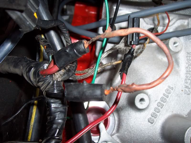
Not sure if it helps but since 70 the solid black shunt has been attached closest to the starter and the black/white has been towards the bulkhead or relay. This pic is where I usually see the solid black connected through the orange fusible link(stuffed under the wiper motor). Sounds as if your prob as you said might be in the bulkhead.

Corvette Stories
The Best of Corvette for Corvette Enthusiasts

Top 10 Most Expensive Corvettes Ever Sold on Bring A Trailer
Brett Foote
10 Things Every Corvette Owner Needs (2026 Edition)
Michael S. Palmer
8 Most "Only Corvette Owners Understand" Quirks and Problems
Pouria Savadkouei
10 Reasons the C6 Z06 is Still A Performance Benchmark After 20 Years
Joe Kucinski
How Much Horsepower Every Corvette Engine "LOST" in 1972
Joe Kucinski
Top 10 DOs and DON'Ts for Protecting Your Convertible Top!
Michael S. Palmer
Top 10 Most Explosive Corvettes Ever Made: Power-to-Weight Ratio Ranked!
Joe Kucinski
150 hp to 1,250 hp: Every Corvette Generation Compared by the Specs That Matter
Joe Kucinski
8 Coolest Corvette Pace Cars (and Replicas) of All Time
Verdad GallardoRace Director
Joined: May 2006
Posts: 16,528
Likes: 53
From: Dayton, Ohio
Team Owner


Joined: Jan 2006
Posts: 37,637
Likes: 3,118
From: Crossville TN
The run of 'power' wiring that is terminated by the two leads going to the ammeter IS the shunt. There is no other 'device' that acts as a shunt other than that wiring. That length of wire has [approx.] the correct resistance as needed by the ammeter (which is really a millivolt meter but has a scale calibrated in "AMPS") to be used as a 'shunt' for the meter. As current is flowing through that main power wire, the current flow causes a proportional voltage drop across that length of wire [between the two lines connected to the meter]. The meter then reads that voltage level and displays it as AMPS with the needle. Note: The vehicle current does NOT flow into the meter's feeder lines...only through the main power wire.
You need to use an ohmeter to find the 'break' in the wiring that is causing your problem. You either have a bad fusible link, a fatigued wire (inside the insulation), or a defective component that is preventing electrical connection.
You need to use an ohmeter to find the 'break' in the wiring that is causing your problem. You either have a bad fusible link, a fatigued wire (inside the insulation), or a defective component that is preventing electrical connection.
Melting Slicks
Joined: Mar 2005
Posts: 2,095
Likes: 299
From: Midlothian VA
Thanks for the reply Fred.
The 75 doesn't use the horn relay as a junction, horn relay is under the dash, but the circuit is similar.
Both the fuse links for the shunts tested good at the junction box (bulkhead connector) so it's likely the terminals in the box.
Try to get to that today.
The 75 doesn't use the horn relay as a junction, horn relay is under the dash, but the circuit is similar.
Both the fuse links for the shunts tested good at the junction box (bulkhead connector) so it's likely the terminals in the box.
Try to get to that today.
Thread Starter
Race Director
Joined: Mar 2006
Posts: 14,112
Likes: 28
From: Florida
Thanks for the pic.
The run of 'power' wiring that is terminated by the two leads going to the ammeter IS the shunt. There is no other 'device' that acts as a shunt other than that wiring. That length of wire has [approx.] the correct resistance as needed by the ammeter (which is really a millivolt meter but has a scale calibrated in "AMPS") to be used as a 'shunt' for the meter. As current is flowing through that main power wire, the current flow causes a proportional voltage drop across that length of wire [between the two lines connected to the meter]. The meter then reads that voltage level and displays it as AMPS with the needle. Note: The vehicle current does NOT flow into the meter's feeder lines...only through the main power wire.
You need to use an ohmeter to find the 'break' in the wiring that is causing your problem. You either have a bad fusible link, a fatigued wire (inside the insulation), or a defective component that is preventing electrical connection.
You need to use an ohmeter to find the 'break' in the wiring that is causing your problem. You either have a bad fusible link, a fatigued wire (inside the insulation), or a defective component that is preventing electrical connection.
I just wanted to know the exact location of the splices on a 75 to save some time. Mine's a very early 75 and the schematics I looked at don't quite jive with it.
Good info nonetheless for people with older cars.
Didn�t fuss with the ammeter today, wanted to get the dash reassembled and all the parts laying around taken care of.
Tested the stereo and dash after assembly today and a lot of strange things were happening.
Stereo would turn on and off with the turn signals with engine running.

Battery was down a bit.
Used an induction ammeter at the alternator to check for charging and it would charge 55 amps for a half second or so and then nothing and would repeat at random.
Found this broken terminal on the signal wire. Don�t know how long it�s been bouncing around in the molex.

Thread Starter
Race Director
Joined: Mar 2006
Posts: 14,112
Likes: 28
From: Florida
I finally got around to tracking down the splices and the ammeter now works.
Although the car was pretty unmolested, the wiring at the starter was butchered, as is often the case. Worst part was cleaning everything to see.
The black/white stripe shunt lead comes out at the firewall connector as 20ga fusible link, changes to a 10ga black/white stripe, then is spliced into the the red 10ga charge wire inside the harness.
The black shunt lead comes out of the firewall connector as black and runs in the engine harness all the way close to the starter, where there should have been another 20ga fusible link after the 14ga link. All were replaced with link wire at one time.
The problem was that the black shunt lead was cut from the link and taped inside the harness. There was also a crip butt connector inside the wrap for the charge wire.
I assume someone thought it was a ground wire since it was black. Perhaps a black with a different colored tracer would have been a better choice originally.
I ended up installing all new fusible links at the starter and reconnecting the black shunt lead.
Hope this helps someone chasing this down on a 75. Seems to be a year all by itself.