


Kinsler Injection
Thread Starter
Drifting


Joined: Oct 2005
Posts: 1,527
Likes: 148
From: East London/SW Essex UK

Calling all you Injection Heads - a point of discussion here!. I run a 528 hp 489 'stroker' engine with Brodix RR Ovals. From a nostalgia point of view I want to go with an individual runner EFI system to replicate that 60's through the hood gasser look. Kinsler seem to be the only manufacturer who actually do a bespoke oval port unit - albeit current units are three piece and slightly lower in height. I have been offered the one piece unit pictured above which has 2 1/4" or 2 3/8" runners. But look how high the fuel rails are mounted. They are located 'above' the 'butterflies' rather than below!. Logic (to me) is that this must be an 'old school' way of doing things and only really effective on WOT race engines. I would guess that on idle and small throttle openings the injectors would be shrouded by the butterfies. Perhaps the castings can be drilled/machined with the fuel rails mounted at a suitable angle lower on the casting and add a vacumn hook-up to each intake runner. Or should I give up on this idea and go with an Inglese IDF inlet and injection throttle bodies?


Last edited by roscobbc; Jan 13, 2011 at 04:29 PM.
Pro


Joined: Jun 2004
Posts: 543
Likes: 2
From: Miami FL
St. Jude Donor '11, '14
It is not as much of a problem as you might think. Carb venturi's are above the butterflies and so are Throttle body injection injectors. Fuel standoff at idle can be a problem. Think of a fog of gas above the stacks. Your intake does seem to have a set of bosses lower down that could be machined too accept conventional injectors. Either way plumbing in a common vacuum set up is advisable for good idle quality.
Rob
Rob
Team Owner


Joined: Apr 1999
Posts: 21,953
Likes: 1,445
From: Reno Nevada
2024 C3 of the Year Finalist- Modified
That is very old school. Probably one of the first kinsler designs.
The problem with that is that it was designed for a mechanical constant squirt or maybe retrofited with some kind of injection timing. You want the injector in the cylinder or as close to it as possible because you get into wet flow and dry flow problems. The fuel actually takes up part of air flow.
The problem with that is that it was designed for a mechanical constant squirt or maybe retrofited with some kind of injection timing. You want the injector in the cylinder or as close to it as possible because you get into wet flow and dry flow problems. The fuel actually takes up part of air flow.
Thread Starter
Drifting
Joined: Oct 2005
Posts: 1,527
Likes: 148
From: East London/SW Essex UK
That is very old school. Probably one of the first kinsler designs.
The problem with that is that it was designed for a mechanical constant squirt or maybe retrofited with some kind of injection timing. You want the injector in the cylinder or as close to it as possible because you get into wet flow and dry flow problems. The fuel actually takes up part of air flow.
The problem with that is that it was designed for a mechanical constant squirt or maybe retrofited with some kind of injection timing. You want the injector in the cylinder or as close to it as possible because you get into wet flow and dry flow problems. The fuel actually takes up part of air flow.
Racer


Joined: Jul 2008
Posts: 338
Likes: 4
From: Bowling Green Kentucky
Give Kinsler a call and discuss it with them. I used to run their stuff years ago in a nitro application. There was a guy there named Brad that I always worked with... very knowledgeable. They would deliver my systems wet flowed and nearly spot on out of the box. They were incredibly great people to work with.

Melting Slicks

Joined: Mar 2002
Posts: 2,164
Likes: 7
From: Beringen
The distance the injector needs to be from the valve is a function of rpm. The higher the rpm is the further away the injector needs to be, in order to give the fuel a chance to vaporize due to the wirleffect in the intake tract.
If the injector is high, this causes more problems at low rpm running, since fuel droplets will end up on the throttle plate and intake tract, making the mixture lean.
Probably this was a manifold designed for use with alcohol. Alcohol needs more time and heat to vaporize.
If the injector is high, this causes more problems at low rpm running, since fuel droplets will end up on the throttle plate and intake tract, making the mixture lean.
Probably this was a manifold designed for use with alcohol. Alcohol needs more time and heat to vaporize.
Thread Starter
Drifting
Joined: Oct 2005
Posts: 1,527
Likes: 148
From: East London/SW Essex UK
The distance the injector needs to be from the valve is a function of rpm. The higher the rpm is the further away the injector needs to be, in order to give the fuel a chance to vaporize due to the wirleffect in the intake tract.
If the injector is high, this causes more problems at low rpm running, since fuel droplets will end up on the throttle plate and intake tract, making the mixture lean.
Probably this was a manifold designed for use with alcohol. Alcohol needs more time and heat to vaporize.
If the injector is high, this causes more problems at low rpm running, since fuel droplets will end up on the throttle plate and intake tract, making the mixture lean.
Probably this was a manifold designed for use with alcohol. Alcohol needs more time and heat to vaporize.
Corvette Stories
The Best of Corvette for Corvette Enthusiasts

Top 10 Most Expensive Corvettes Ever Sold on Bring A Trailer
Brett Foote
10 Things Every Corvette Owner Needs (2026 Edition)
Michael S. Palmer
8 Most "Only Corvette Owners Understand" Quirks and Problems
Pouria Savadkouei
10 Reasons the C6 Z06 is Still A Performance Benchmark After 20 Years
Joe Kucinski
How Much Horsepower Every Corvette Engine "LOST" in 1972
Joe Kucinski
Top 10 DOs and DON'Ts for Protecting Your Convertible Top!
Michael S. Palmer
Top 10 Most Explosive Corvettes Ever Made: Power-to-Weight Ratio Ranked!
Joe Kucinski
150 hp to 1,250 hp: Every Corvette Generation Compared by the Specs That Matter
Joe Kucinski
8 Coolest Corvette Pace Cars (and Replicas) of All Time
Verdad Gallardo
Melting Slicks
Joined: Mar 2002
Posts: 2,164
Likes: 7
From: Beringen
There is another aspect to this setup. The bores are pretty large. This means it will be difficult to tune (lots of air displacement with a small amount of throttle plate movement)
My guess is it will be cheaper/beter to run a dedicated manifold. I have a crossram ITB setup, but i got it from Australia. It's a quality made piece. They also have a straight up type itb system. Would have to check for their co�rdinates.
Thread Starter
Drifting
Joined: Oct 2005
Posts: 1,527
Likes: 148
From: East London/SW Essex UK
I think for street use, you will need to modify it and put the injectors more downstream. Don't know the layout, but it could be you're running into problems with the linkage.
There is another aspect to this setup. The bores are pretty large. This means it will be difficult to tune (lots of air displacement with a small amount of throttle plate movement)
My guess is it will be cheaper/beter to run a dedicated manifold. I have a crossram ITB setup, but i got it from Australia. It's a quality made piece. They also have a straight up type itb system. Would have to check for their co�rdinates.
Could use current vacumn hook-ups (below throttle plates) as a datum surface to machine for re-positioning injectors?
Is your cross ram unit a rect or oval port unit?
Melting Slicks
Joined: Mar 2002
Posts: 2,164
Likes: 7
From: Beringen
My setup is rectangular type, itb bores are 50 mm which is plenty for about 640 hp.
You should ask around, but all I here is that a large bore, makes it pretty sensitive to throttle changes and thus difficult to tune. A larger bore is normally used for high rpm potential.
I would think this setup is a drag race type manifold.
Melting Slicks

Joined: Feb 2006
Posts: 2,209
Likes: 0
From: Mo
Well Kinsler can do all that you need to make it bolt on. THere is nothing like the look and performance of a Kinsler efi. I have run it several different engine I use a FAST controler.
Convert it electronic you wont regret it
Convert it electronic you wont regret it


Le Mans Master


Joined: Apr 2007
Posts: 7,353
Likes: 72
From: Graceland in a Not Correctly Restored Stingray
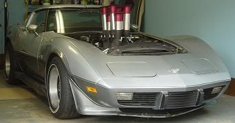
In case you're interested in a 2.9" Crower/McKay, as seen in the Chevy Power book BB section...
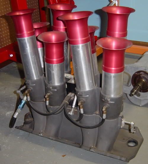
...I have one that needs to find a good home, including an extra set of stacks (NIB) and other bits. You'd need to do some epoxy work in the runners to match your heads, but according to basic calculations this would put you very near the ~2.8" ideal throttle bore size for a healthy 489. This is not a toy. Yes, injection above the butterflies is old school, but they can be readily relocated while converting it to EFI, if desired. Also, there's plenty of room underneath for hidden nitrous. Don't have a pic of it thru a hood (have an extra one for that purpose), but here's an idea of how it sits in a C3...

TSW
...I have one that needs to find a good home, including an extra set of stacks (NIB) and other bits. You'd need to do some epoxy work in the runners to match your heads, but according to basic calculations this would put you very near the ~2.8" ideal throttle bore size for a healthy 489. This is not a toy. Yes, injection above the butterflies is old school, but they can be readily relocated while converting it to EFI, if desired. Also, there's plenty of room underneath for hidden nitrous. Don't have a pic of it thru a hood (have an extra one for that purpose), but here's an idea of how it sits in a C3...
TSW
Last edited by TheSkunkWorks; Jan 15, 2011 at 05:41 PM.
Thread Starter
Drifting
Joined: Oct 2005
Posts: 1,527
Likes: 148
From: East London/SW Essex UK
Excellent SkunkWorks !!!!!!! - just what the doctor (or shrink) ordered to help me with my '60s gasser obsession. I actually can source an unused Crower 2.9" mech set-up for not a lot of money this side of the pond - but I don't really want to do all the epoxy work - yes the idea of hidden nitrous has occurred to me as has a custom removeable acrylic cover/bulge (al la kinda ZR1?) to go over shorter trumpets and keep out weather and occasional peanuts or stones thrown by bystanders. 
Jenvy system available in Europe

Camaro with Kinsler system

Jenvy system available in Europe
Camaro with Kinsler system
Melting Slicks
Joined: Mar 2002
Posts: 2,164
Likes: 7
From: Beringen
What are you going to use as an air filtration on those ?
I was going to use the 'sock' type foam filter soaked in oil... But these are underhood units + i'm planning on building a cold air unit around it. Don't car much about the bling bling factor. I want to see the face of other people thinking my car is just a regular L82, when they get beaten in a drag race.
I was going to use the 'sock' type foam filter soaked in oil... But these are underhood units + i'm planning on building a cold air unit around it. Don't car much about the bling bling factor. I want to see the face of other people thinking my car is just a regular L82, when they get beaten in a drag race.
Thread Starter
Drifting
Joined: Oct 2005
Posts: 1,527
Likes: 148
From: East London/SW Essex UK
What are you going to use as an air filtration on those ?
I was going to use the 'sock' type foam filter soaked in oil... But these are underhood units + i'm planning on building a cold air unit around it. Don't car much about the bling bling factor. I want to see the face of other people thinking my car is just a regular L82, when they get beaten in a drag race.
I was going to use the 'sock' type foam filter soaked in oil... But these are underhood units + i'm planning on building a cold air unit around it. Don't car much about the bling bling factor. I want to see the face of other people thinking my car is just a regular L82, when they get beaten in a drag race.
Skunkworks - I would be interested in a tutorial from you on sizing of intake runners

Le Mans Master
Joined: Apr 2007
Posts: 7,353
Likes: 72
From: Graceland in a Not Correctly Restored Stingray
I did say "basic" calculations, and should qualify that the ~2.8" includes a number of assumptions. In order to more accurately size them for max performance you'd need to factor in max head flow at max intake valve lift for the cam in question, projected VE%'s, and intended peak HP RPM (RPMpp) among other factors. Obviously, the formula for doing so are a bit involved, but it boils down to meeting your specific CFM requirements as precisely as you can.
It's also worth pointing out that IR diameter and length on the intake side affect torque/power curves in a similar way as do header primary dimensions, tho in the latter instance we're dealing with much higher velocities (due to the greatly expanded gases) and collector scavenging. In any event, rather than your relying on any formula of mine (and of which I'm still somewhat less than certain) I should best defer to what a real FI engineer advises for your particular application. Might be an interesting exercise to crunch the numbers tho...
It's also worth pointing out that IR diameter and length on the intake side affect torque/power curves in a similar way as do header primary dimensions, tho in the latter instance we're dealing with much higher velocities (due to the greatly expanded gases) and collector scavenging. In any event, rather than your relying on any formula of mine (and of which I'm still somewhat less than certain) I should best defer to what a real FI engineer advises for your particular application. Might be an interesting exercise to crunch the numbers tho...
Last edited by TheSkunkWorks; Jan 16, 2011 at 10:48 PM.
Le Mans Master

Joined: Oct 2007
Posts: 6,007
Likes: 1,746
From: Richmond Kentucky
2025 Corvette of the Year Winner- Modified
2024 C2 of the Year Winner - Modified
2022 Corvette of the Year Finalist -- Modified
2021 C2 of the Year Winner - Modified
2021 C1 of the Year Winner - Modified
2020 Corvette of the Year (stock)
C2 of Year Winner (stock) 2019
2017 C1 of the Year Finalist
Can you post a pic of your crossram unit?
