


C3 Headlight Door Alignment

Thread Starter
Cruising

Joined: Mar 2012
Posts: 11
Likes: 3
From: Long Island NY
Sharing the fruits of my hard labor. I've seen a number of incomplete and/or erroneous posts on this subject, so I reasoned out the process and tested it on my 76. Here are the steps in the correct order. Do this with the engine not running and no vacuum in the reservoir, or you could get pinched fingers (or worse). Remove the grill (5 screws) so you can reach the mechanism from the front as well as from underneath.
1. If a new installation, center the headlight door in the opening by adjusting the pivot points and the collars (on the hinge posts) at the upper rear corners of the assembly. Hold the door in the closed position and adjust the pivot points until the corners of the door are aligned with the corners of the opening. Don't worry about the final open/closeed height at this point - just be sure the door is centered and on the same plane as the surrounding bodywork when held in the closed position. Tighten the pivot point mounting bolts and verify the alignment is still correct in the closed position.
2. Loosen the 3 bolts on the bracket in front of the vacuum actuator (NOT the ones on the vacuum actuator itself) - the ones that locate the bracket holding the linkage with the springs and the clevis (remove the clevis to get at the center bolt). To remove the clevis, first remove the 2 springs that attach to the clevis pin, then the cotter pin and the clevis pin itself. The other 2 springs can stay attached.
3. Adjust the full open height with the adjusting bolt - the one on the arm that contacts the headlight frame when full open. Out is lower, in is higher. Use a long socket extension and a universal joint to reach the adjusting bolt through the grill opening. Make the bottom of the bezel flush with the front edge of the opening.
4. Actuate the mechanism by hand so you can feel the "over center" condition when the door is fully open and the linkage fully extended forward. Move the bracket until you get a slight interference fit - the linkage gently, but firmly, "snaps" forward into the over center position when you actuate it manually. Tighten the 3 bolts loosened in step 2.
5. Adjust the clevis by turning it on its shaft until the clevis pin (the rod that goes through the clevis, and where the springs mount) is all the way to the front of the curved slot it rides in. Remove the clevis pin and turn the clevis 1 to 1 1/2 turns counterclockwise to give a slight interference fit at the end of its travel in the open position. The clevis must extend enough to push the linkage into the over center position, which is what locks the door in the open position. The interference fit ensures this locking, and prevents rattles too.
6. Last step - adjust the closed position with the small hex bolt - this is in the center of the linkage, and points down at the ground when the door is closed. The hex is small - the same size as the diameter of the bolt itself. Adjust so the front edge of the door is about 1/32" inch lower than the front edge of the opening. This will minimize wind noise and water entry.
7. Test. The door should snap into full open firmly, with a click, but not a thud. If it makes a loud thud or a bang, re-do step 4. The thud means the over center position is too tight, and this will put too much strain on the linkage, damaging it over time.
Note: It goes without saying, but just in case, you should use a good lubricant on all pivot points and moving parts in the linkage.
Le Mans Master


Joined: Aug 2006
Posts: 7,423
Likes: 1,558
From: mount holly NC
2025 c3 ('74-'82) of the Year Finalist - Unmodified
2019 C3 of Year Finalist (appearance mods)
That is a very good "How-to", thanks for taking the time to write it up.
Regards, Pete
PS Welcome to the forum!
Regards, Pete
PS Welcome to the forum!
Safety Car


Joined: Sep 2011
Posts: 4,114
Likes: 1,230
From: Madeira Beach, FL
2024 C8 of the Year Finalist - Unmodified
2024 C2 of the Year Finalist - Unmodified
2023 C2 of the Year Finalist - Unmodified
2020 C3 of the Year Finalist - Unmodified
Thank you very much for the very informative and well written article.
I too have the passenger side thud when my door opens.
Now I know why.
It also opens slower than the drivers side???
Mine is a 1968.
Any thoughts on this one??
Marshal
I too have the passenger side thud when my door opens.
Now I know why.
It also opens slower than the drivers side???
Mine is a 1968.
Any thoughts on this one??
Marshal
Thread Starter
Cruising
Joined: Mar 2012
Posts: 11
Likes: 3
From: Long Island NY
It's probably opening slower due to the linkage being too tight. Mine would open most of the way normally, then wait for enough vacuum to build up to overcome the tight linkage, then it would make the "thunk" sound and snap into the full open position. The actuator itself could be weak, but probably not if it has the strength to overcome the tight linkage in the first place. Same for a vacuum leak - if there was a bad leak the door would never open fully. So I would adjust the linkage first, make sure all moving parts are well lubricated, and then test. And thank you for your kind comments on my post.
Safety Car
Joined: Sep 2011
Posts: 4,114
Likes: 1,230
From: Madeira Beach, FL
2024 C8 of the Year Finalist - Unmodified
2024 C2 of the Year Finalist - Unmodified
2023 C2 of the Year Finalist - Unmodified
2020 C3 of the Year Finalist - Unmodified
Scott,
thanks for the advise
Alan suggested it might be an actuator seal leaking.
I'll try the linkage adjustment first and then work on the seal
If the linkage adjustment does not completely correct the situation
It has to be a seal
Thank you,
Marshal
thanks for the advise
Alan suggested it might be an actuator seal leaking.
I'll try the linkage adjustment first and then work on the seal
If the linkage adjustment does not completely correct the situation
It has to be a seal
Thank you,
Marshal
Corvette Stories
The Best of Corvette for Corvette Enthusiasts

Top 10 Most Explosive Corvettes Ever Made: Power-to-Weight Ratio Ranked!
Joe Kucinski
150 hp to 1,250 hp: Every Corvette Generation Compared by the Specs That Matter
Joe Kucinski
8 Coolest Corvette Pace Cars (and Replicas) of All Time
Verdad Gallardo
Top 10 Corvette Engines RANKED by Peak Torque (70+ Years of Muscle!)
Joe Kucinski
Corvette ZR1X Will Be Pacing the Indy 500, And Could Probably Race, Too!
Verdad Gallardo
Top 10 Corvettes Coming to Mecum Indy 2026!
Brett Foote
Top 10 C9 Corvette MUST-HAVES to Fix These C8 Generation Flaws!
Michael S. Palmer
10 Revolutionary 'Corvette Firsts' Most People Don't Know
Joe Kucinski
5 Reasons to Upgrade to an LS6-Powered Corvette; 5 Reasons to Stay LT2
Michael S. Palmer
Pro

Joined: May 2011
Posts: 581
Likes: 5
From: BC
Very good piece. The one thing I'm not sure about is the lubrication thing. All the pivot points are on nylon "self lubricating" (GM's terminology) bushings and the pins zinc plated. When nylon bushings are used it is generally so that you can avoid grease which will catch the road dirt causing binding and excessive wear from the grit they hold. I didn't look in the assembly manual, but there was no evidence of lubricant when I stripped them (whereas I did find remnants of lubricant on the headlight adjuster screws into their plastic stands). The manuals is at work, but I will check it tomorrow.
I assembled them dry and they move beautifully. They certainly don't need lube to function properly at this point (new). The question is what will be working best after a few years exposed to the elements.
Steve g
I assembled them dry and they move beautifully. They certainly don't need lube to function properly at this point (new). The question is what will be working best after a few years exposed to the elements.
Steve g
Thread Starter
Cruising
Joined: Mar 2012
Posts: 11
Likes: 3
From: Long Island NY
Steve - On an assembly that was rebuilt with new parts I would agree 100% - no lube is better.
On an assembly that has a lot of years/miles on it though, there is already some grit and dirt embedded in the nylon bushings, any zinc coating is usually long gone, and there is typically wear and some misalignment on many of the components.
So in lieu of doing a complete rebuild, I found that a good coating of grease keeps things actuating smoothly and fills in some of the excess clearance, which to my thinking helps keep some of the dirt and crud out of the mechanism. As you correctly pointed out, it will trap some dirt as well, but I felt the benefits outweighed the negatives for a well worn asembly. But you are correct that it was originally designed as lube-free. Thank you for the clarification.
Scott
Pro
Joined: May 2011
Posts: 581
Likes: 5
From: BC
Steve - On an assembly that was rebuilt with new parts I would agree 100% - no lube is better.
On an assembly that has a lot of years/miles on it though, there is already some grit and dirt embedded in the nylon bushings, any zinc coating is usually long gone, and there is typically wear and some misalignment on many of the components.
So in lieu of doing a complete rebuild, I found that a good coating of grease keeps things actuating smoothly and fills in some of the excess clearance, which to my thinking helps keep some of the dirt and crud out of the mechanism. As you correctly pointed out, it will trap some dirt as well, but I felt the benefits outweighed the negatives for a well worn asembly. But you are correct that it was originally designed as lube-free. Thank you for the clarification.
Scott
On an assembly that has a lot of years/miles on it though, there is already some grit and dirt embedded in the nylon bushings, any zinc coating is usually long gone, and there is typically wear and some misalignment on many of the components.
So in lieu of doing a complete rebuild, I found that a good coating of grease keeps things actuating smoothly and fills in some of the excess clearance, which to my thinking helps keep some of the dirt and crud out of the mechanism. As you correctly pointed out, it will trap some dirt as well, but I felt the benefits outweighed the negatives for a well worn asembly. But you are correct that it was originally designed as lube-free. Thank you for the clarification.
Scott
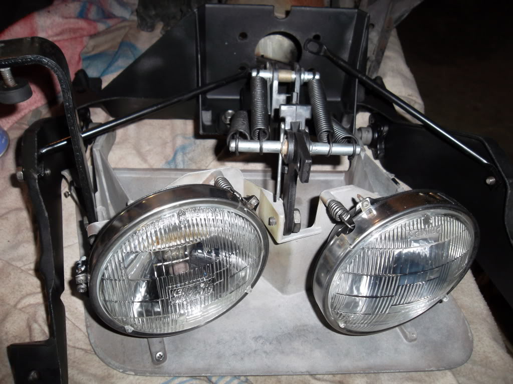
One thing about lubing. On the pivots at the three bolt hinges, the pin and the collar were unprotected steel, vs plating on other pins. From that and examining the hinge it appears to me that it was intentional that they be allowed to rust. I believe the self centering bushing on the hinge should not turn on the shaft. The bushing is nylon in alum and while alum will oxidise, as long as it moves periodically should not cause the problem that a nylon bushing on bare metal would. Plus the ball like bushing is meant to centre in the little support so it would seem logical that it also pivots in the support.
In short, don't grease the pin. If you are going to grease it, get your lube between the bushing and the alum bushing support.
Steve g
Thread Starter
Cruising
Joined: Mar 2012
Posts: 11
Likes: 3
From: Long Island NY
Steve - nice picture, and nice restoration work.
On the lube issue, I didn't intend to start a controversy. For my purposes, some of my parts were worn and/or corroded so I chose to lube them (waterproof marine grease) for smooth operation and to protect against further corrosion. Mission accomplished. I don't plan to go to NCRS, so I wasn't going to go crazy. That's it. The decision to lube is up to the individual - it works for me, but may not for everyone else. But no matter which way you go, having the assenbly adjusted properly will make a bigger difference than lube / no lube will. Thanks for the lively discussion.
Scott
Pro
Joined: May 2011
Posts: 581
Likes: 5
From: BC
Steve - nice picture, and nice restoration work.
On the lube issue, I didn't intend to start a controversy. For my purposes, some of my parts were worn and/or corroded so I chose to lube them (waterproof marine grease) for smooth operation and to protect against further corrosion. Mission accomplished. I don't plan to go to NCRS, so I wasn't going to go crazy. That's it. The decision to lube is up to the individual - it works for me, but may not for everyone else. But no matter which way you go, having the assenbly adjusted properly will make a bigger difference than lube / no lube will. Thanks for the lively discussion.
Scott
On the lube issue, I didn't intend to start a controversy. For my purposes, some of my parts were worn and/or corroded so I chose to lube them (waterproof marine grease) for smooth operation and to protect against further corrosion. Mission accomplished. I don't plan to go to NCRS, so I wasn't going to go crazy. That's it. The decision to lube is up to the individual - it works for me, but may not for everyone else. But no matter which way you go, having the assenbly adjusted properly will make a bigger difference than lube / no lube will. Thanks for the lively discussion.
Scott
bring a different option/prospective to the table. If I hadn't replated the pins I too would use grease. Just wanted others to know that if they have the plated pins dry assembly might be an option for them. Added the part about the pivot because I puzzled over them at first, assuming the bushings turned on the pins rather than in the mount. Thought I would share it.
Again, sorry if I offended.
Steve g
Thread Starter
Cruising
Joined: Mar 2012
Posts: 11
Likes: 3
From: Long Island NY
Steve - No offense taken. One thing about Corvette enthusiasts is that we tend to be passionate about our cars, which is what makes it fun when we get together to exchange ideas. It also means we tend to be detail oriented, which is also a good thing. In fact, that's the reason I wrote in the first place. I simply could not find a comprehensive set of instructions anywhere. The Corvette Assembly Manual is written for the assembler who is mounting a factory assembled and adjusted unit in the car, not working on a 35+ year old unit that has been through a lot, so it simply did not have the detail necessary for us enthusiasts. I hope my small contribution helps someone, and with your elaboration, it makes for an even more complete picture. My next project is taking out the dash to replace all the bulbs, correctly re-install the A/C ductwork, and properly secure the wiring harness. Good time to check out the lower windshield frame for rust (a common issue), not that there is much you can do about it without complete disassembly and welding. But it will be nice to know what's underneath the covers.
Pro
Joined: May 2011
Posts: 581
Likes: 5
From: BC
Steve - No offense taken. One thing about Corvette enthusiasts is that we tend to be passionate about our cars, which is what makes it fun when we get together to exchange ideas. It also means we tend to be detail oriented, which is also a good thing. In fact, that's the reason I wrote in the first place. I simply could not find a comprehensive set of instructions anywhere. The Corvette Assembly Manual is written for the assembler who is mounting a factory assembled and adjusted unit in the car, not working on a 35+ year old unit that has been through a lot, so it simply did not have the detail necessary for us enthusiasts. I hope my small contribution helps someone, and with your elaboration, it makes for an even more complete picture. My next project is taking out the dash to replace all the bulbs, correctly re-install the A/C ductwork, and properly secure the wiring harness. Good time to check out the lower windshield frame for rust (a common issue), not that there is much you can do about it without complete disassembly and welding. But it will be nice to know what's underneath the covers.
Which is what makes your write up such a welcome contribution. Saves everyone from going through what you had to do to figure it out. Pour over the drawings and specs and put meaningful instructions into print.
It sounds like I'm not far behind you. I have the body off and the underhood area pretty much stripped and components detailed. I'm moving inside to remove the rest of the HVAC , steering column and brake booster so I can finish the engine compartment. Discovered that in order to remove the frt light harness I have to remove the fibre optics from the instrument panel so I'll be in there now as well.
Steve g

5th Gear
Joined: Feb 2013
Posts: 5
Likes: 0
From: norwood ma
Scott, GREAT POST! I was just about to order the Assembly Manual (even after reading your post) but further into the thread told me not to bother.
I'm excited to try your procedure, as my "hit-and-miss" method is eroding my patience!
Thanx again, and wish me luck,
TKD
I'm excited to try your procedure, as my "hit-and-miss" method is eroding my patience!
Thanx again, and wish me luck,
TKD
Team Owner


Joined: Sep 2006
Posts: 31,214
Likes: 4,302
From: Westminster Maryland
Hi TKD,
FIRST POST!!!
Welcome!
I think most people find the AIM and GM Chassis Service Manual for the year Corvette they're working on to be VITAL!
The AIM is especially useful in determining what has been done to the car over the years, and is a road map to getting it back to a point that it can actually be worked on.
Give it a try!
Regards,
Alan
Melting Slicks

Joined: Sep 2011
Posts: 3,372
Likes: 215
From: Peoria Arizona
Hi TKD,
FIRST POST!!!
Welcome!
I think most people find the AIM and GM Chassis Service Manual for the year Corvette they're working on to be VITAL!
The AIM is especially useful in determining what has been done to the car over the years, and is a road map to getting it back to a point that it can actually be worked on.
Give it a try!
Regards,
Alan
FIRST POST!!!
Welcome!
I think most people find the AIM and GM Chassis Service Manual for the year Corvette they're working on to be VITAL!
The AIM is especially useful in determining what has been done to the car over the years, and is a road map to getting it back to a point that it can actually be worked on.
Give it a try!
Regards,
Alan
 My AIM was the best money I have spent (on cars or other) in a very, very long time. I don't want to drive up the price, but for the amount of information contained in them and the amount of time it continues to save me, it could double in price and still be worth the money.