


'71 door ajar switch replacement
Thread Starter
Burning Brakes


Joined: Feb 2011
Posts: 850
Likes: 12
From: Shakopee MN
In my previous thread, I was discussing, IMHO, the poor design of the switch. I basically don't trust that little finger to not slip off the plastic and now my switch doesn't work any more.
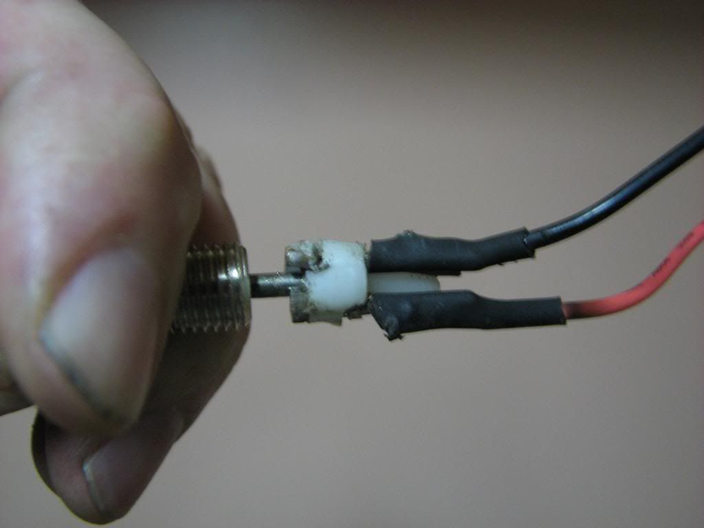
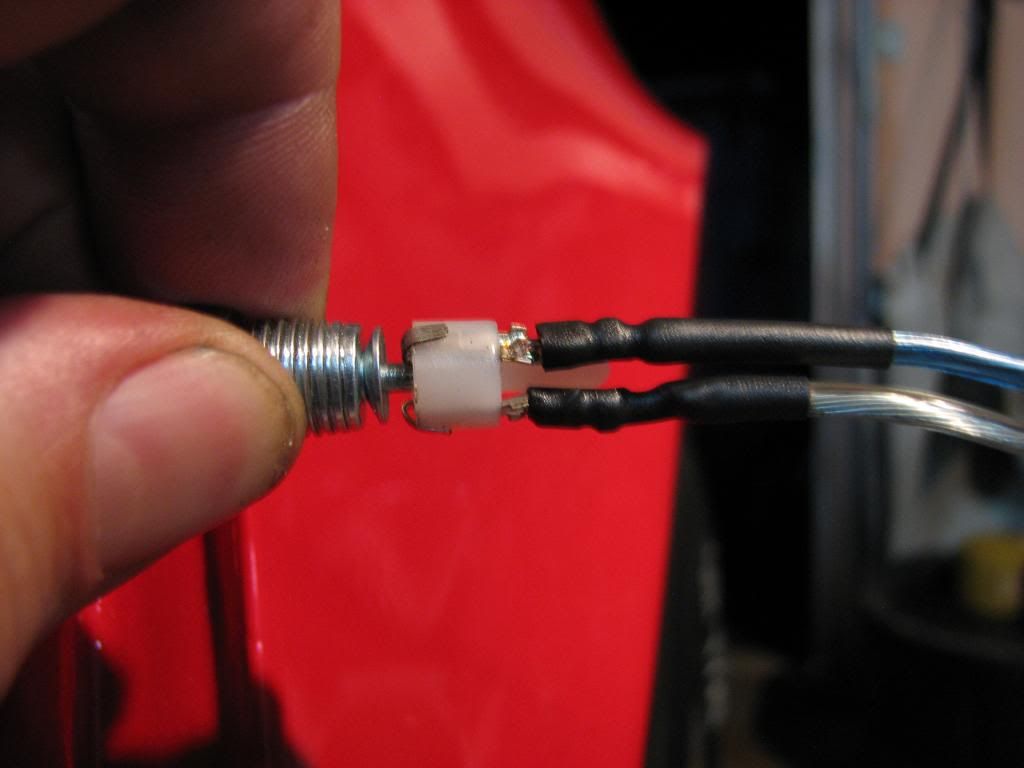
So last year I tried some crude experiments with my switch, one of which ended up with me taking some nails and fabricating my own connector that go through that white plastic piece on the switch. It worked for a while and then failed, it wasn't a pretty piece of work as shown here:
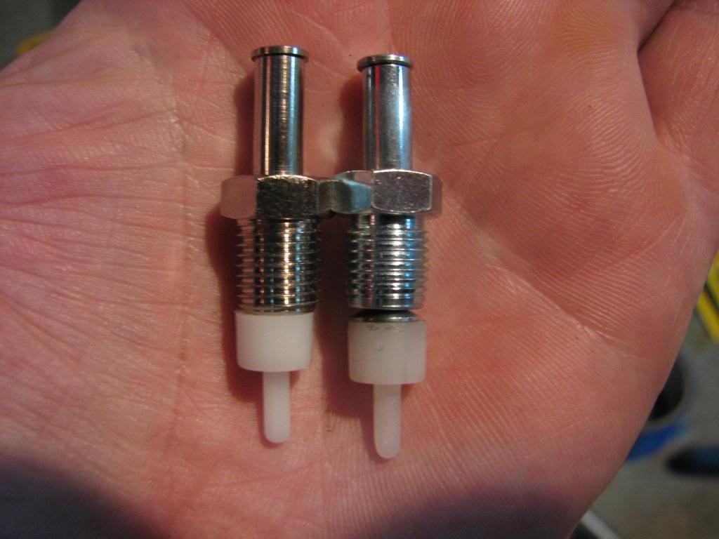
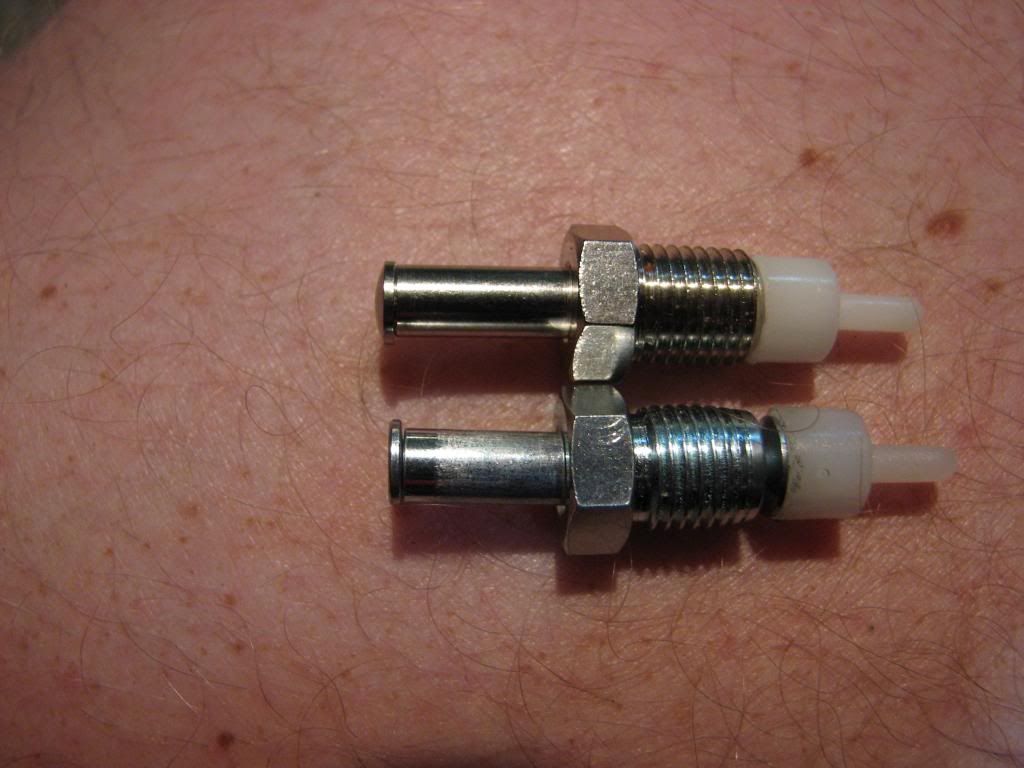
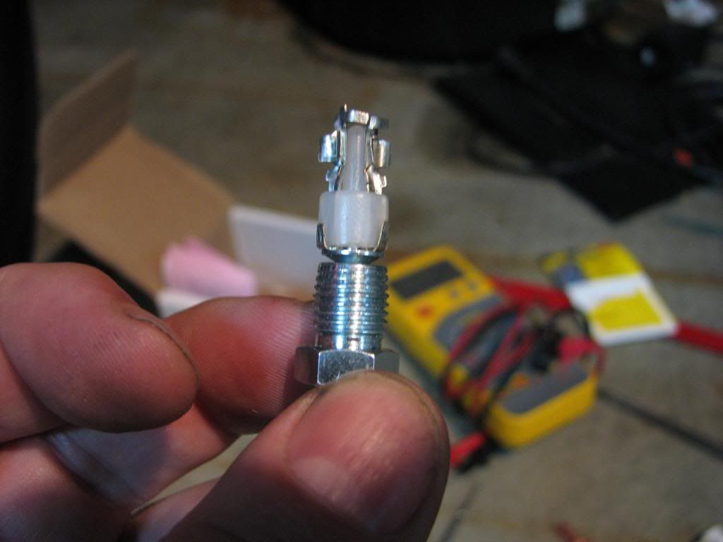
So with my switch not working, it was always in the back of my mind that my center console light wouldn't come on. Not a big deal really, but I want everything to work on my car. So I ordered up some more switches from Lectric Limited and one other Corvette specialty place. The LL and 'vette vendor switch appear similar but there are subtle differences as can be seen here:
Notably the LL version has the correct XS (or is it SX) stamping:
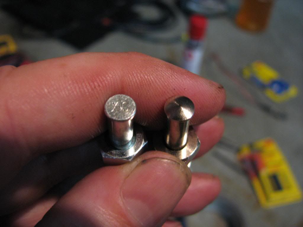
also note the slight length difference and the top is round vs flat:
I also ordered 2 sets of the 6 connectors so that I had plenty to work with in case I screwed up:
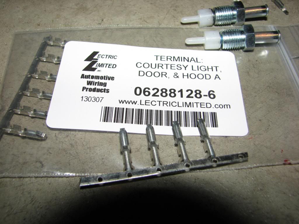
I did on mockup with 2 of the connectors to make sure that bending the tabs on the *outside* would still fit through the hole, it did:
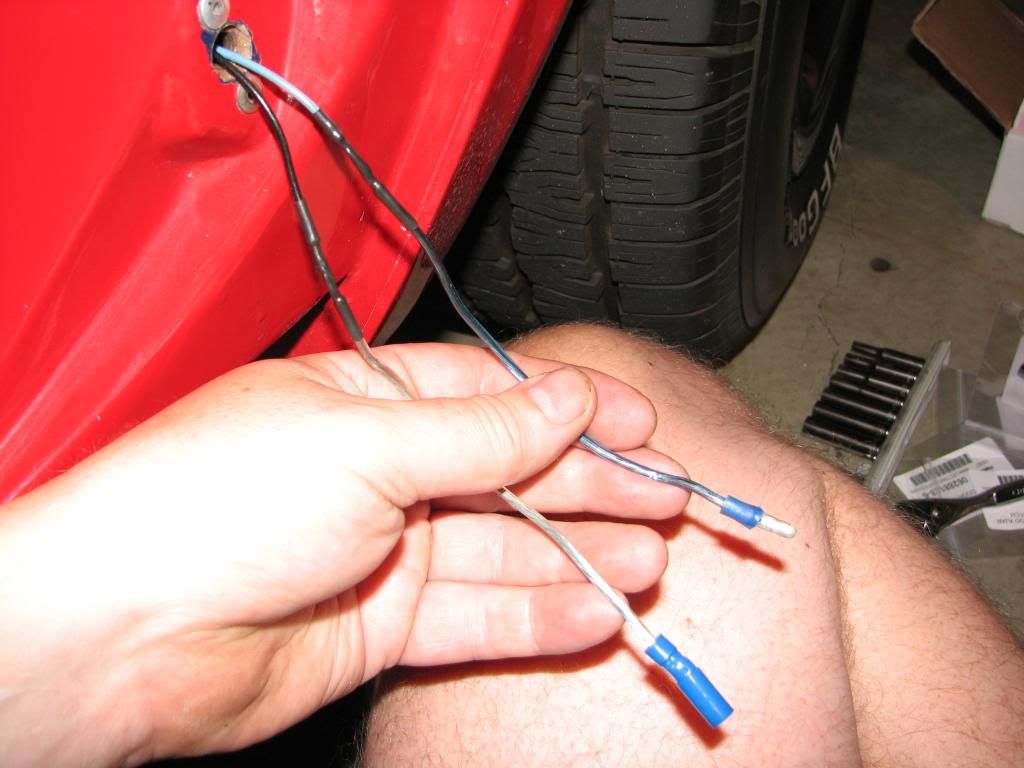
So I got going on my electrical by soldering in some new lines and fishing them through the hole:
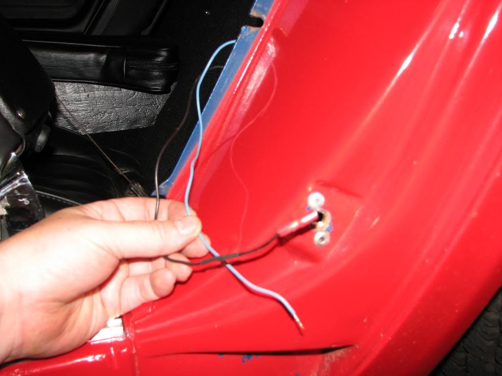
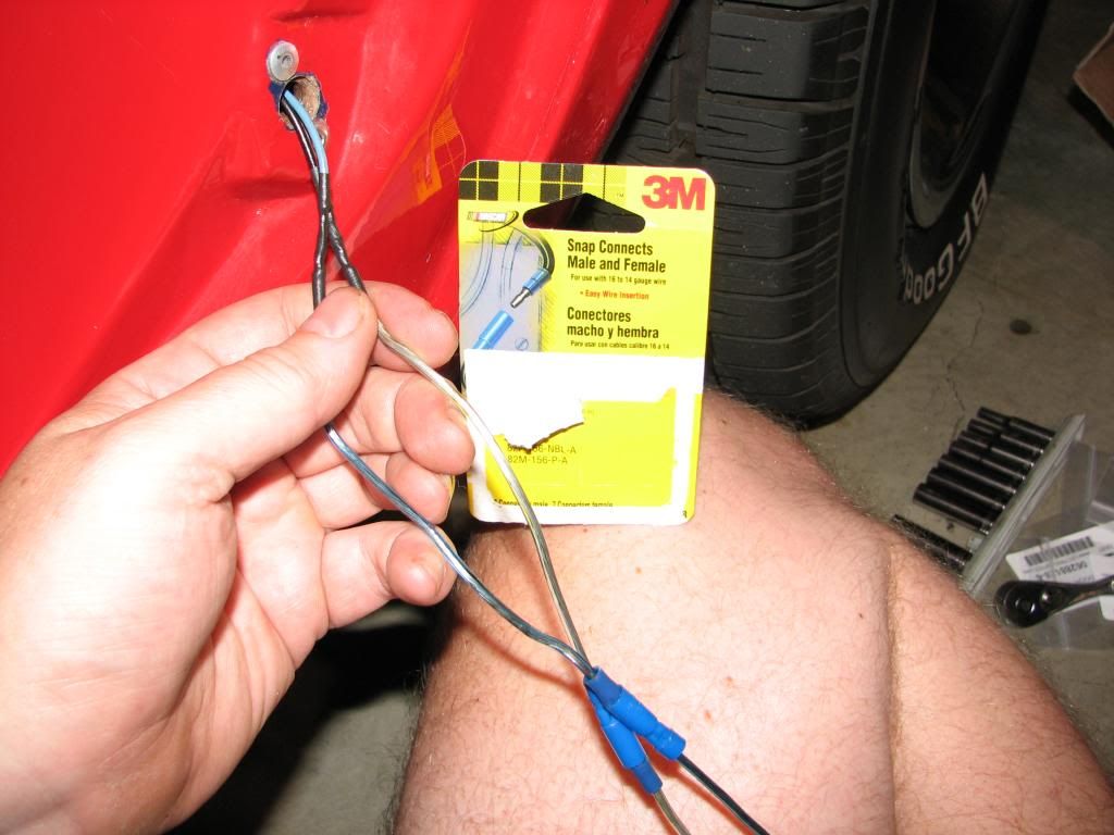
Previously I had used the square 1/4" quick disconnects, but had a tough time fitting them through the hole. So this time I went with some round versions of the snap connects:
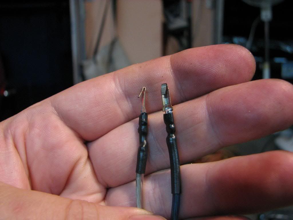
So I soldered up my tab connectors...
...and bent the tabs so they would fit through the white plastic holes...
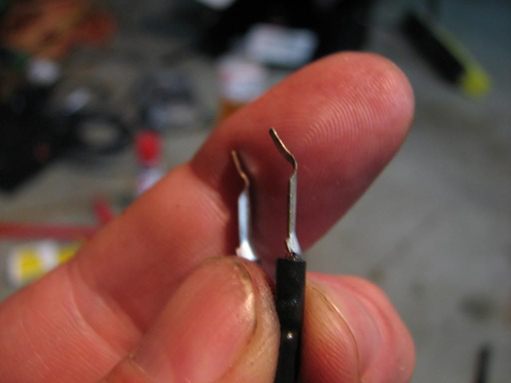
...they did. So I bent the tabs over nice and snug. You can't bend that metal too much or it will easily snap!
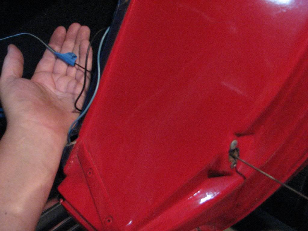
Then I just had to button it up:
Woohoo, now I've got a functioning "Door Ajar" light! Small miracles keep the motivation high.
So you ask "Why use the snap disconnects at all?". Good question and my answer is that if I ever have to do this again, I want to make sure that it can be easily disconnected from the wire to work on it.
So last year I tried some crude experiments with my switch, one of which ended up with me taking some nails and fabricating my own connector that go through that white plastic piece on the switch. It worked for a while and then failed, it wasn't a pretty piece of work as shown here:
So with my switch not working, it was always in the back of my mind that my center console light wouldn't come on. Not a big deal really, but I want everything to work on my car. So I ordered up some more switches from Lectric Limited and one other Corvette specialty place. The LL and 'vette vendor switch appear similar but there are subtle differences as can be seen here:
Notably the LL version has the correct XS (or is it SX) stamping:
also note the slight length difference and the top is round vs flat:
I also ordered 2 sets of the 6 connectors so that I had plenty to work with in case I screwed up:
I did on mockup with 2 of the connectors to make sure that bending the tabs on the *outside* would still fit through the hole, it did:
So I got going on my electrical by soldering in some new lines and fishing them through the hole:
Previously I had used the square 1/4" quick disconnects, but had a tough time fitting them through the hole. So this time I went with some round versions of the snap connects:
So I soldered up my tab connectors...
...and bent the tabs so they would fit through the white plastic holes...
...they did. So I bent the tabs over nice and snug. You can't bend that metal too much or it will easily snap!
Then I just had to button it up:
Woohoo, now I've got a functioning "Door Ajar" light!
Small miracles keep the motivation high.So you ask "Why use the snap disconnects at all?". Good question and my answer is that if I ever have to do this again, I want to make sure that it can be easily disconnected from the wire to work on it.
Last edited by StingrayLust; Jul 19, 2013 at 02:31 AM.
Le Mans Master


Joined: Dec 2003
Posts: 5,381
Likes: 416
From: N J
Nice job and pics.
My only question is are you sure those tabs get bent like in the next to last pic? I thought they just push in and snap into position when they pop out the other side. Either way glad you are up and running.
My only question is are you sure those tabs get bent like in the next to last pic? I thought they just push in and snap into position when they pop out the other side. Either way glad you are up and running.
Thread Starter
Burning Brakes
Joined: Feb 2011
Posts: 850
Likes: 12
From: Shakopee MN
I just got fed up with the way the tab never caught like it should have when it's used as it should be with the metal tab popping open inside the white plastic container to prevent it coming out further. It always seemed that it was too easy to pull out. So hence why I made damn sure that it's not going to come out now!

Pro


Joined: Jan 2001
Posts: 511
Likes: 66
From: Timnath, CO
I may be doing this job in the near future. Right now there is just a hole where the switch belongs. The wires are probably just sitting behind the hole somewhere. Can you elaborate on how you got to the original wires and "fished" them through the hole?
Thanks
Thanks
Thread Starter
Burning Brakes
Joined: Feb 2011
Posts: 850
Likes: 12
From: Shakopee MN
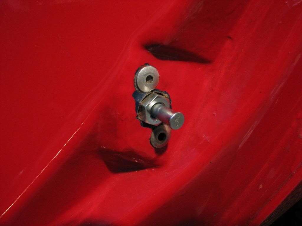
Question though, are your rivets around the switch hole still in place? If not, the metal bracket that the switch goes into has probably fallen in the space behind the opening. It can be tough to get back at that piece.
Pro
Joined: Jan 2001
Posts: 511
Likes: 66
From: Timnath, CO
It's quite easy. Just remove the rear quarter panel and the wires feed in from the inside just behind that panel. I used a metal flag marker I had laying around to fish the wire through the inside to outside holes to make the connection.
Question though, are your rivets around the switch hole still in place? If not, the metal bracket that the switch goes into has probably fallen in the space behind the opening. It can be tough to get back at that piece.
Question though, are your rivets around the switch hole still in place? If not, the metal bracket that the switch goes into has probably fallen in the space behind the opening. It can be tough to get back at that piece.
Corvette Stories
The Best of Corvette for Corvette Enthusiasts

Top 10 Most Expensive Corvettes Ever Sold on Bring A Trailer
Brett Foote
10 Things Every Corvette Owner Needs (2026 Edition)
Michael S. Palmer
8 Most "Only Corvette Owners Understand" Quirks and Problems
Pouria Savadkouei
10 Reasons the C6 Z06 is Still A Performance Benchmark After 20 Years
Joe Kucinski
How Much Horsepower Every Corvette Engine "LOST" in 1972
Joe Kucinski
Top 10 DOs and DON'Ts for Protecting Your Convertible Top!
Michael S. Palmer
Top 10 Most Explosive Corvettes Ever Made: Power-to-Weight Ratio Ranked!
Joe Kucinski
150 hp to 1,250 hp: Every Corvette Generation Compared by the Specs That Matter
Joe Kucinski
8 Coolest Corvette Pace Cars (and Replicas) of All Time
Verdad Gallardo
Thread Starter
Burning Brakes
Joined: Feb 2011
Posts: 850
Likes: 12
From: Shakopee MN
I wouldn't expect the LL switch to withstand a whole lot more pressure before bending, but I do think it's a more quality switch. That said, I had bought 2 of the LL switches. One of them the metal interior shaft that connects to the white plastic piece has sort of a rough surface on it for lack of a better word. What I mean is that when I push the plunger down, there are times it seems to catch the bottom metal lip on the shaft causing a brief moment of extra force needed. Luckily only 1 of the 2 LL switches was really bad. The 3rd party generic switch exhibited none of those rough shaft problems. I'd be worried that if it caught hard enough, over time that it might break off my rivets caused by that repeated stress.
I had tried to sand that shaft down but I guess I failed as it didn't seem to clear up the issue. I'd order 2 of the LL switches to be safe and then post on here your experiences. If I could marry the 2 switches together, the LL and the generic one, taking the best from each I'd have a perfect switch. Close but no cigar, ahh the life of a Corvette restorer.
The SX stamping I believe is supposed to be correct if you're into the NCRS stuff.
Pro
Joined: Jan 2001
Posts: 511
Likes: 66
From: Timnath, CO
Is there a trick to getting the switch screwed into the backing plate? The plate is till riveted in, but I cant seem to get the switch to take hold. It's almost like I am cross threading it, because I get resistance on the wrench, but then it gets loose. The other weird thing is I can't get the switch back out. I can pull the threaded part out of the hole by pulling on the shaft, but the plastic part with the terminals won't come out with it. It's like they are hanging up behind the backing plate. The good news is that the door ajar light I working now! I just don't have the switch bolted in right (bubba?). Next up is the passenger side, which should be more straight forward as the old switch is still bolted in, and hopefully the wires are still there behind the panel.
Drifting


Joined: Jul 2004
Posts: 1,695
Likes: 65
From: Kissimmee fl
Finalist 2021 C3 of the Year - Modified
2017 C3 of Year Finalist
Cruise-In VIII Veteran
St. Jude Donor '07
The carbon steel backing plates are now being reproduced to aid in this repair. My guess is that the threads in the original plate have rusted away, thus preventing you from screwing in the switch properly.
When I had my car painted, I made the plates out of Stainless Steel pop riveted them in. The switch threads are 3/8-16 UNC.
I could not dig out the old plates after they dropped into the abyss behind the panel, so I just let them stay burried there
When I had my car painted, I made the plates out of Stainless Steel pop riveted them in. The switch threads are 3/8-16 UNC.
I could not dig out the old plates after they dropped into the abyss behind the panel, so I just let them stay burried there
Pro
Joined: Jan 2001
Posts: 511
Likes: 66
From: Timnath, CO
The carbon steel backing plates are now being reproduced to aid in this repair. My guess is that the threads in the original plate have rusted away, thus preventing you from screwing in the switch properly.
When I had my car painted, I made the plates out of Stainless Steel pop riveted them in. The switch threads are 3/8-16 UNC.
I could not dig out the old plates after they dropped into the abyss behind the panel, so I just let them stay burried there
When I had my car painted, I made the plates out of Stainless Steel pop riveted them in. The switch threads are 3/8-16 UNC.
I could not dig out the old plates after they dropped into the abyss behind the panel, so I just let them stay burried there

