




New Wiring Engine & Chassis

Thread Starter
Instructor

Joined: Oct 2013
Posts: 222
Likes: 4
From: Cameron Park California
 New Wiring Engine & Chassis
I am considering replacing the wiring on my 74 with new wiring possibly a custom harness that includes the engine harness wiring for the LS1 swap. My concern is when upgrading to the more powerful alternator will the stock wiring hold up? Am I being overly concerned? What have others done?
Thanks!
Thanks!
Le Mans Master


Joined: May 2003
Posts: 8,876
Likes: 3,556
From: Fernandina Beach FL
2023 Restomod of the Year finalist
2020 C3 of the Year Winner - Modified
Hey Steven-
These cars were NOT designed to handle anywhere near the electrical loads that are added today....Think of the Alt as your income-and the battery as your bank account-and the small wire as bank fees...
I am basically going to run the stock harness and add on extra circuits-fuse panel to handle the new stuff I am adding for my swap.
Basics of wire- as they heat up-they add resistance-whether is be from a large current draw (electric fans) or the heat from the engine.
So the larger the better.
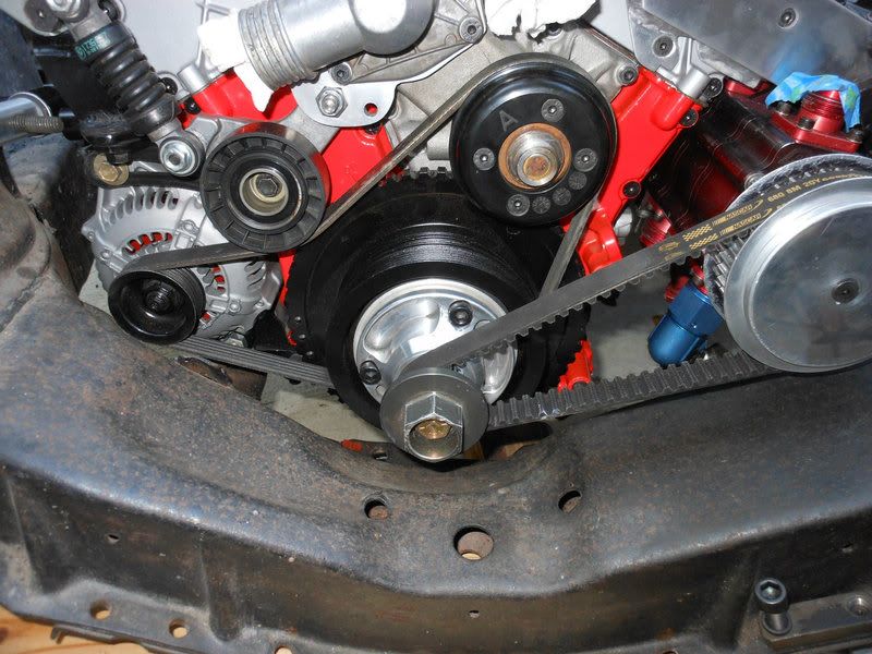
Also remember when your car is idling- the alt is not going to be putting out it's rated output- so again bigger is better -also look at putting a smaller pulley on the alt(opposite of what the tuners/ricers are doing) because if/when you are sitting in traffic you want the electric fans and AC to be working-even if you give up a few HP.
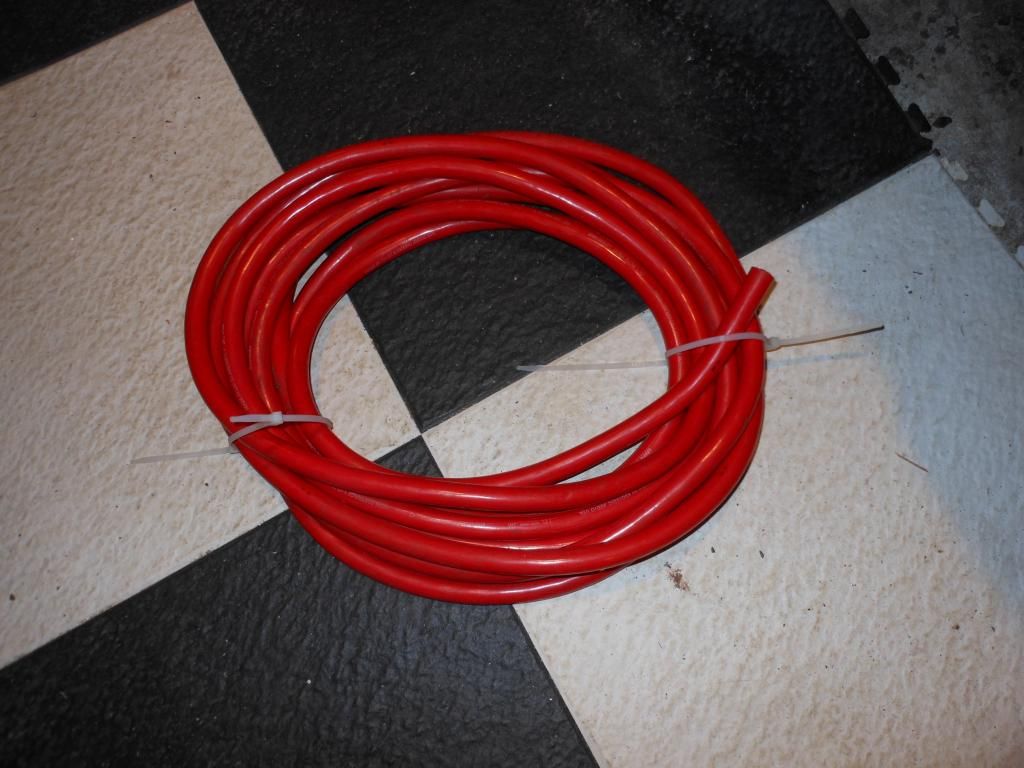
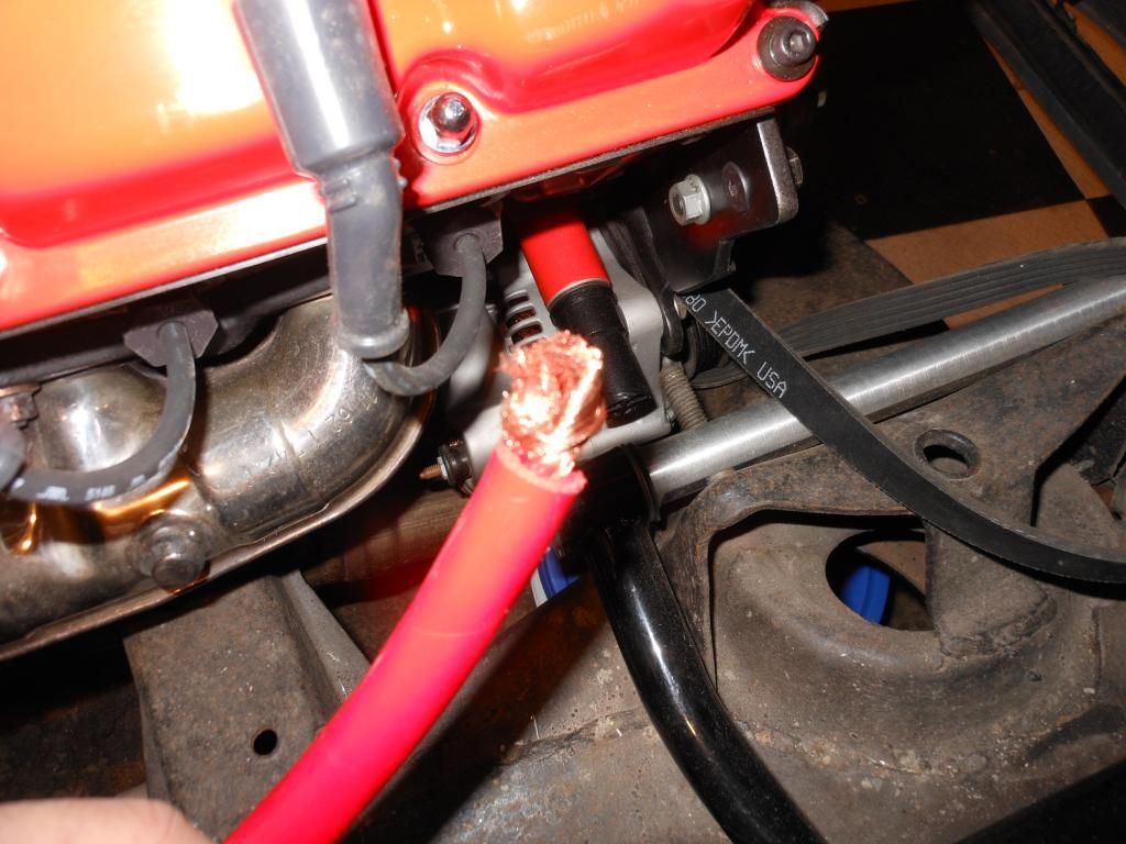
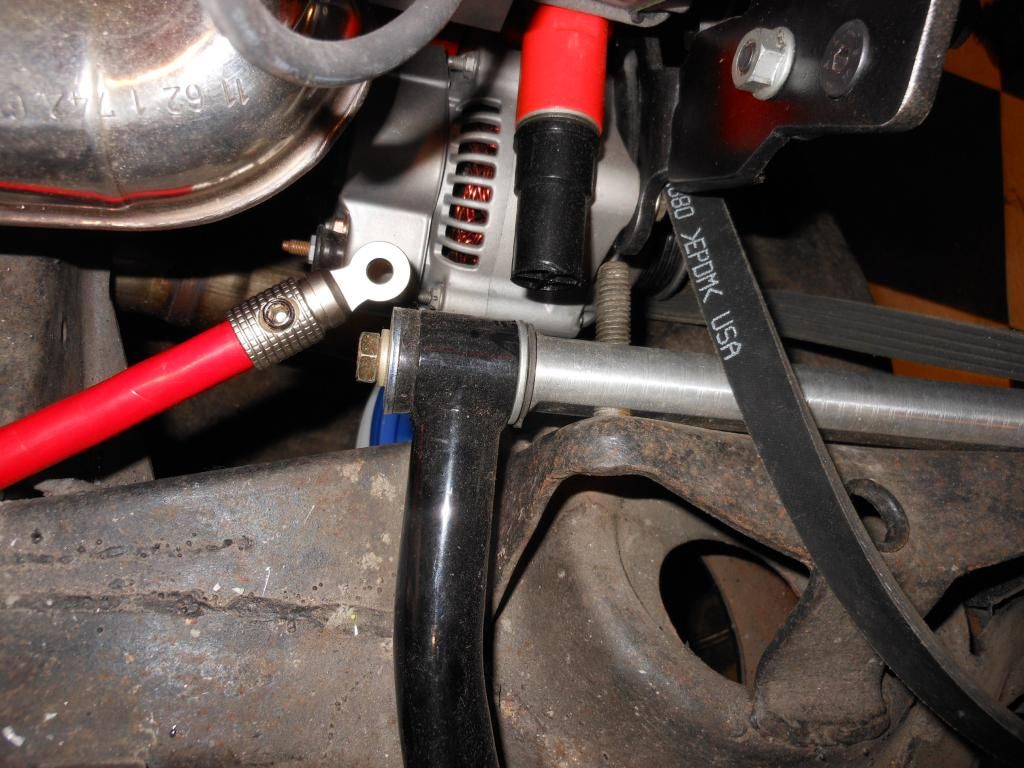
See pic- went w/ the smallest pulley I could find- and running 0 gauge wire.
AND - the ammeter will not read correctly after you upgrade-to solve this I had my ammeter converted to a voltmeter.
Hope this helps...
Richard
These cars were NOT designed to handle anywhere near the electrical loads that are added today....Think of the Alt as your income-and the battery as your bank account-and the small wire as bank fees...
I am basically going to run the stock harness and add on extra circuits-fuse panel to handle the new stuff I am adding for my swap.
Basics of wire- as they heat up-they add resistance-whether is be from a large current draw (electric fans) or the heat from the engine.
So the larger the better.
Also remember when your car is idling- the alt is not going to be putting out it's rated output- so again bigger is better -also look at putting a smaller pulley on the alt(opposite of what the tuners/ricers are doing) because if/when you are sitting in traffic you want the electric fans and AC to be working-even if you give up a few HP.
See pic- went w/ the smallest pulley I could find- and running 0 gauge wire.
AND - the ammeter will not read correctly after you upgrade-to solve this I had my ammeter converted to a voltmeter.
Hope this helps...
Richard


Thread Starter
Instructor
Joined: Oct 2013
Posts: 222
Likes: 4
From: Cameron Park California
Gary,
I am thinking similar to what you describe run the larger 8 or 6 gauge wire from the alternator to the starter and then tap power for the LS1 engine harness from there. Are you tapping into "Switched Power" from the existing fuse box with a larger wire as well?
I am thinking similar to what you describe run the larger 8 or 6 gauge wire from the alternator to the starter and then tap power for the LS1 engine harness from there. Are you tapping into "Switched Power" from the existing fuse box with a larger wire as well?

Race Director


Joined: Apr 2007
Posts: 11,150
Likes: 890
From: South Western Ontario
No, you also run the power off the solenoid and use a relay to switch it on and off. The coil of the relay is powered off the stock wiring so it has power with the key on. Old coil power wire, IGN terminal in fuse block etc can be used for the source.

Burning Brakes

Joined: Oct 2008
Posts: 1,037
Likes: 14
From: Mobile Alabama
I am considering replacing the wiring on my 74 with new wiring possibly a custom harness that includes the engine harness wiring for the LS1 swap. My concern is when upgrading to the more powerful alternator will the stock wiring hold up? Am I being overly concerned? What have others done?
Thanks!
Thanks!

It is actually a Silverado box I re-worked and probably a little overkill, as I have more individual circuits and relays than most purchased harnesses. It ties back into the original at a terminal block then to the starter cable. My late model alternator is ECU controlled and again goes to the terminal block. Using relays, I just use the original start circuit for a trigger.

Le Mans Master
Joined: May 2008
Posts: 9,063
Likes: 2,736
2022 C3 of the Year Finalist - Modified
When I see people adding all this stuff, I realize how lucky I am. My Vette is not going to have a radio, no antenna, no airconditioning, no heater and all the silly vacuum controls, no windshield washer, maybe windshield wipers (just in case)?, don't care about door light switches that turn on an silly overhead lights, no cigarette lighter, no alarms or buzzers ........just bare bones, sports car for driving for fun! Who needs all that stuff when you have a Corvette....take the T-tops off, and listen to the beauty of that Chevy 350 for all the music one needs!
Burning Brakes
Joined: Oct 2008
Posts: 1,037
Likes: 14
From: Mobile Alabama
When I see people adding all this stuff, I realize how lucky I am. My Vette is not going to have a radio, no antenna, no airconditioning, no heater and all the silly vacuum controls, no windshield washer, maybe windshield wipers (just in case)?, don't care about door light switches that turn on an silly overhead lights, no cigarette lighter, no alarms or buzzers ........just bare bones, sports car for driving for fun! Who needs all that stuff when you have a Corvette....take the T-tops off, and listen to the beauty of that Chevy 350 for all the music one needs!
By the way, I have a car with no windows, door locks, and no key (think small and English). No music other than the engine, and the top stays down.

Le Mans Master
Joined: May 2003
Posts: 8,876
Likes: 3,556
From: Fernandina Beach FL
2023 Restomod of the Year finalist
2020 C3 of the Year Winner - Modified
You really want your electronics running off the battery....
The battery does a couple things which electronics really like-
1)Stabilizes the voltage- keeps surges/spikes to a minimum-like when starting the car- the electronics would MUCH rather see the battery as a source than at the starter which there IS going to be a voltage drop.
2) Filters out the AC noise coming from the alternator- the Alt makes AC voltage then it's converted to DC...but as the Alt ages filtering is not as effective....
Although there is always disagreements on what's the best way...I have looked and many a high end car- and they ALWAYS wire the electronics directly off the battery and run a separate charging wire directly from the alt to the battery. And FWIW -if you do a stereo/amp- don't run your power wires or preamp wires anywhere near the alt wire- you'll get noise.
So a 6-8GU wire run from the output of the Alt directly to either the starter -or all the way back to the battery is the way to go.
Use a relay-switched w/ a wire from the original fuse block- and its power directly connected to the battery-is how I recommend running the LS harness/ECU.
I like the Silverado box... I'm using a couple 5 circuit fuse blocks out of a 7 Series BMW ( found under the back seat- a couple bucks at the junkyard)
One fuse block will be "hot" all the time- for running things not switched w/ ignition. ( power windows, stereo amp, etc)
And the second box will be switched w/ an ignition wire controlling a 40A relay that will turn the whole fuse block "on" when the ignition is on. (fuel pump, ECU,etc)
Richard
The battery does a couple things which electronics really like-
1)Stabilizes the voltage- keeps surges/spikes to a minimum-like when starting the car- the electronics would MUCH rather see the battery as a source than at the starter which there IS going to be a voltage drop.
2) Filters out the AC noise coming from the alternator- the Alt makes AC voltage then it's converted to DC...but as the Alt ages filtering is not as effective....
Although there is always disagreements on what's the best way...I have looked and many a high end car- and they ALWAYS wire the electronics directly off the battery and run a separate charging wire directly from the alt to the battery. And FWIW -if you do a stereo/amp- don't run your power wires or preamp wires anywhere near the alt wire- you'll get noise.
So a 6-8GU wire run from the output of the Alt directly to either the starter -or all the way back to the battery is the way to go.
Use a relay-switched w/ a wire from the original fuse block- and its power directly connected to the battery-is how I recommend running the LS harness/ECU.
I like the Silverado box... I'm using a couple 5 circuit fuse blocks out of a 7 Series BMW ( found under the back seat- a couple bucks at the junkyard)
One fuse block will be "hot" all the time- for running things not switched w/ ignition. ( power windows, stereo amp, etc)
And the second box will be switched w/ an ignition wire controlling a 40A relay that will turn the whole fuse block "on" when the ignition is on. (fuel pump, ECU,etc)
Richard
Corvette Stories
The Best of Corvette for Corvette Enthusiasts

Top 10 Most Explosive Corvettes Ever Made: Power-to-Weight Ratio Ranked!
Joe Kucinski
150 hp to 1,250 hp: Every Corvette Generation Compared by the Specs That Matter
Joe Kucinski
8 Coolest Corvette Pace Cars (and Replicas) of All Time
Verdad Gallardo
Top 10 Corvette Engines RANKED by Peak Torque (70+ Years of Muscle!)
Joe Kucinski
Corvette ZR1X Will Be Pacing the Indy 500, And Could Probably Race, Too!
Verdad Gallardo
Top 10 Corvettes Coming to Mecum Indy 2026!
Brett Foote
Top 10 C9 Corvette MUST-HAVES to Fix These C8 Generation Flaws!
Michael S. Palmer
10 Revolutionary 'Corvette Firsts' Most People Don't Know
Joe Kucinski
5 Reasons to Upgrade to an LS6-Powered Corvette; 5 Reasons to Stay LT2
Michael S. Palmer
Thread Starter
Instructor
Joined: Oct 2013
Posts: 222
Likes: 4
From: Cameron Park California
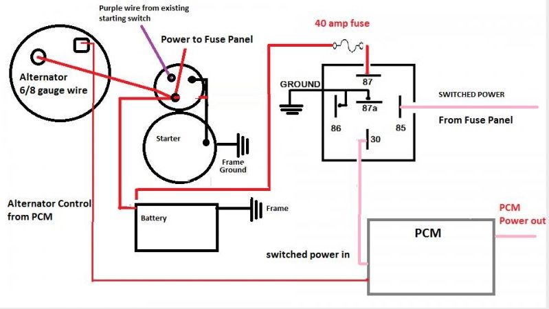
Hopefully I my drawing is correct? I did check my wiring diagram but it was unclear that I could tap into switched power in the engine bay vs. going back to the fuse panel?
Last edited by mmesa005; Jan 14, 2014 at 01:07 AM.
Le Mans Master
Joined: May 2003
Posts: 8,876
Likes: 3,556
From: Fernandina Beach FL
2023 Restomod of the Year finalist
2020 C3 of the Year Winner - Modified
Here's a my thoughts- power the relay-hence the electronics right off the battery. Don't really need a fuse as high as 40A if you are just running the electronics. You can also use the output of the relay (#30) to power say the electric fuel pump or anything else you want switched w/ the ignition.
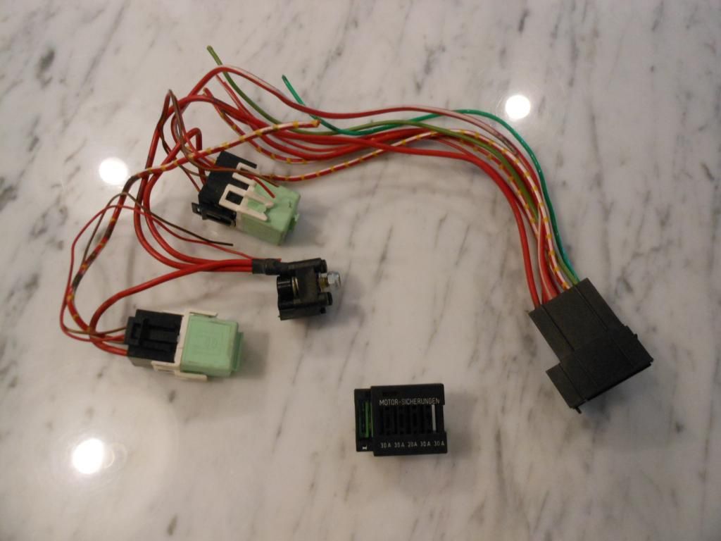
Here's the fuse block I was talking about-
Has a nice lug to hook up power w/ a standoff- two relays to control the 5 circuits- fuses have a neat sliding cover and very compact. Plus the wires are rated for automotive use...not true for the stuff at Harbor Freight.....
Richard
Here's the fuse block I was talking about-
Has a nice lug to hook up power w/ a standoff- two relays to control the 5 circuits- fuses have a neat sliding cover and very compact. Plus the wires are rated for automotive use...not true for the stuff at Harbor Freight.....
Richard


Last edited by Richard454; Jan 14, 2014 at 10:09 AM.

Team Owner


Joined: Jul 1999
Posts: 65,492
Likes: 230
From: Orange Park Florida
Back in '95 when doing the FI conversion, I left all the factory wiring intact, charge wires, fuse links, the works.....first up was radiator and serp drive in front, changed alt to a 10 SI unit, 108 amps....
I run a separate wire to the fan relay on the shroud.....running dual Spals today, they have their own fuse next to the alt output stud they wired directly to....NOT off the horn relay.....the FI gets a 7.5 amp fuse off the horn relay, to the computer/injectors ....
I added power windows and eliminated all the inside lights years ago......it's a convertible.....I don't even have any door locks on it....

I run a separate wire to the fan relay on the shroud.....running dual Spals today, they have their own fuse next to the alt output stud they wired directly to....NOT off the horn relay.....the FI gets a 7.5 amp fuse off the horn relay, to the computer/injectors ....
I added power windows and eliminated all the inside lights years ago......it's a convertible.....I don't even have any door locks on it....
Thread Starter
Instructor
Joined: Oct 2013
Posts: 222
Likes: 4
From: Cameron Park California
I just want to be comfortable with knowing I am not going to fry the existing wiring with the more powerful alternator from the LS1. I think the way forward is keep existing wiring intact and as described above how to connect the engine/transmission wiring harness/PCM.
Burning Brakes
Joined: Oct 2008
Posts: 1,037
Likes: 14
From: Mobile Alabama
You will need new wiring. The following is about the minimum. I use more fuses and relays than this.
PCM fuse - 15 amp
Inj bank 1 - 15 amp
Inj bank 2 - 15 amp
O2 sensors - 20amp
Trans control solenoid, (auto) - 15 amp
PCM to battery fuse - 10 amp
Fuel Pump thru fuel pump relay - 20 amp
And remember the switched power must be hot/energized when the key switch is in the "ON" position and in the "START" position. If not the PCM will shut off while cranking.
Thread Starter
Instructor
Joined: Oct 2013
Posts: 222
Likes: 4
From: Cameron Park California
Use a wire off of the Alternator rated for it's full output. You can terminate it at the battery, or starter. The old harness cannot be hurt unless you wire something new into it.
You will need new wiring. The following is about the minimum. I use more fuses and relays than this.
PCM fuse - 15 amp
Inj bank 1 - 15 amp
Inj bank 2 - 15 amp
O2 sensors - 20amp
Trans control solenoid, (auto) - 15 amp
PCM to battery fuse - 10 amp
Fuel Pump thru fuel pump relay - 20 amp
And remember the switched power must be hot/energized when the key switch is in the "ON" position and in the "START" position. If not the PCM will shut off while cranking.
You will need new wiring. The following is about the minimum. I use more fuses and relays than this.
PCM fuse - 15 amp
Inj bank 1 - 15 amp
Inj bank 2 - 15 amp
O2 sensors - 20amp
Trans control solenoid, (auto) - 15 amp
PCM to battery fuse - 10 amp
Fuel Pump thru fuel pump relay - 20 amp
And remember the switched power must be hot/energized when the key switch is in the "ON" position and in the "START" position. If not the PCM will shut off while cranking.
Seems we have the same model year? I expect the best place to tap into hot/energized is at the open "accy" slot in the fuse? Where are you tapping in?
Also, I was re-reading the wiring diagram and looking at the car and noted the junction block near the alternator. Should I not also run a 6/8 gauge wire to that junction block? Every time I look at the wiring diagram I keep pondering why there are 2 paths for power into the chassis yet if you just tap power at the starter positive you power the entire car? Make sense?
Last edited by mmesa005; Jan 14, 2014 at 04:32 PM.
Burning Brakes
Joined: Oct 2008
Posts: 1,037
Likes: 14
From: Mobile Alabama
74modified,
Seems we have the same model year? I expect the best place to tap into hot/energized is at the open "accy" slot in the fuse? Where are you tapping in?
Also, I was re-reading the wiring diagram and looking at the car and noted the junction block near the alternator. Should I not also run a 6/8 gauge wire to that junction block? Every time I look at the wiring diagram I keep pondering why there are 2 paths for power into the chassis yet if you just tap power at the starter positive you power the entire car? Make sense?
Seems we have the same model year? I expect the best place to tap into hot/energized is at the open "accy" slot in the fuse? Where are you tapping in?
Also, I was re-reading the wiring diagram and looking at the car and noted the junction block near the alternator. Should I not also run a 6/8 gauge wire to that junction block? Every time I look at the wiring diagram I keep pondering why there are 2 paths for power into the chassis yet if you just tap power at the starter positive you power the entire car? Make sense?
Yes to power to the junction block (again off the top of my head) to send power to original fuse panel.
Thread Starter
Instructor
Joined: Oct 2013
Posts: 222
Likes: 4
From: Cameron Park California
Yes, check the fuse box for switched power. The one to the coil (if I remember correctly) is off during cranking. I dont have the original fuse box anymore - cant stand the glass fuses.
Yes to power to the junction block (again off the top of my head) to send power to original fuse panel.
Yes to power to the junction block (again off the top of my head) to send power to original fuse panel.
Thanks!
Le Mans Master
Joined: May 2003
Posts: 8,876
Likes: 3,556
From: Fernandina Beach FL
2023 Restomod of the Year finalist
2020 C3 of the Year Winner - Modified
Also, I was re-reading the wiring diagram and looking at the car and noted the junction block near the alternator. Should I not also run a 6/8 gauge wire to that junction block? Every time I look at the wiring diagram I keep pondering why there are 2 paths for power into the chassis yet if you just tap power at the starter positive you power the entire car? Make sense?
Again -if you are going to the trouble to rewire the car- you might as well home run the new circuits to the battery-have the relays/fuse in the storage compartment and run new wire to the sources.
The power source for the relay? Like 74 said- the PCM/pump/injectors need to be on while cranking- HOWEVER the relay is going to pull only a 100mA or so- that's milliamps- so the size of the wire (18gu) is fine and for the source-tapping the fusebox won't hurt anything.
Race Director
Joined: Apr 2007
Posts: 11,150
Likes: 890
From: South Western Ontario
In the original wiring, does the wiring from the alternator, starter solenoid and fuse panel not all meet at that junction block? If yes, you can just remove the wires to the alternator and the wire from the solenoid will power the original fuse block.
On the C5/C6 there are 2 wires going to the starter solenoid. The wires are metric but it's about a #6 awg for the charging wire and another about #16 awg for the voltage sensing. Both have fusible links at the solenoid - use 4 awg sizes smaller and about 5" for the fusible link. For example, #10 fusible link for the #6 wire.
Your diagram for the PCM power relay is fine except don't ground the 87a terminal. Also, it will make absolutely no difference using the battery vs the starter solenoid as the connection point. Pick the point which is easier to use for the wiring. I'd much rather have a shorter wire from the solenoid then a longer wire from the battery for under hood power or under dash power. The opposite would be true for accessories mounted under the seats or in the storage compartments.
As a final note - always put wire protection close to the source. I prefer to just solder and heat shrink a fusible link onto the end of the wire and then add a loop lug onto the end of the fusible link. There is double walled heat shrink that has sealant inside to give a very good weatherproof seal.
On the C5/C6 there are 2 wires going to the starter solenoid. The wires are metric but it's about a #6 awg for the charging wire and another about #16 awg for the voltage sensing. Both have fusible links at the solenoid - use 4 awg sizes smaller and about 5" for the fusible link. For example, #10 fusible link for the #6 wire.
Your diagram for the PCM power relay is fine except don't ground the 87a terminal. Also, it will make absolutely no difference using the battery vs the starter solenoid as the connection point. Pick the point which is easier to use for the wiring. I'd much rather have a shorter wire from the solenoid then a longer wire from the battery for under hood power or under dash power. The opposite would be true for accessories mounted under the seats or in the storage compartments.
As a final note - always put wire protection close to the source. I prefer to just solder and heat shrink a fusible link onto the end of the wire and then add a loop lug onto the end of the fusible link. There is double walled heat shrink that has sealant inside to give a very good weatherproof seal.
Thread Starter
Instructor
Joined: Oct 2013
Posts: 222
Likes: 4
From: Cameron Park California
Two paths to run the power -effectively INCREASE the current capacity.
Again -if you are going to the trouble to rewire the car- you might as well home run the new circuits to the battery-have the relays/fuse in the storage compartment and run new wire to the sources.
The power source for the relay? Like 74 said- the PCM/pump/injectors need to be on while cranking- HOWEVER the relay is going to pull only a 100mA or so- that's milliamps- so the size of the wire (18gu) is fine and for the source-tapping the fusebox won't hurt anything.
Again -if you are going to the trouble to rewire the car- you might as well home run the new circuits to the battery-have the relays/fuse in the storage compartment and run new wire to the sources.
The power source for the relay? Like 74 said- the PCM/pump/injectors need to be on while cranking- HOWEVER the relay is going to pull only a 100mA or so- that's milliamps- so the size of the wire (18gu) is fine and for the source-tapping the fusebox won't hurt anything.
After this discussion I don't see a need to rewire the chassis just wire per the above drawing - 6/8 gauge from alternator to starter solenoid and bring switched power from the fuse box to the engine bay to supply power to the LS1 PCM/engine wiring harness.
to answer lionelhutz question, yes, the wire from the starter solenoid goes back to the junction in the above photo. From that junction the alternator connects. I wanted to better understand why the car is wired that way but I think I am making it more complex in my mind than it is? If I understand the wiring correctly it goes as follows:
- Battery Positive Terminal to Starter Soleniod
- Starter Soleniod to Junction block near alternator
- Alternator battery terminal connected to circuit from junction box
- wire from junction box feeds main fuse panel
So, if you run a 6/8 gauge wire from the LS1 alternator to the starter solenoid you have the larger wire to that point and then back to the battery. You then feed the fuse panel using the wire from the original factory harness which I assume is fine? I thought you would want to have 6/8 gauge from the alternator to the starter solenoid and then to the fuse panel but from what I think everyone is saying that is not necessary?
Race Director
Joined: Apr 2007
Posts: 11,150
Likes: 890
From: South Western Ontario
Overall, yes what you describe for the chassis wiring is correct and it's really not all that complex.
One thing not mentioned yet. The voltage sensing wire for the alternator also goes to the junction block. So, the alternator is trying to regulate the junction block to 14.2V and then all the other parts of the car are powered from that point. It's not a big deal exactly how this is done if your wiring is heavy enough though.
The 2 fusible link black & black/white wires tapping off the wire between the junction block and the solenoid are for the ammeter. If you don't include those wires in the new charging circuit then the ammeter will always display a discharge. However, paralleling the old wires with a new wire to try and include the old wiring isn't be best way to do it.
What I would likely do to still make the ammeter work. I would run the new alternator wires (charging and voltage sensing) to the junction block (or a new heavy duty one) and upgrade the wire from the junction to the solenoid too. I believe the old wire is #10 and I would use #6 for the new wire so I would try to make the new wire between those 2 ammeter wires about 1.26 times as long as the original. That way, the ammeter would read 1/2 of the true current and it would not get pegged by the higher current. You could also go with the same length of wire and the ammeter would read about 2.5 times less current. Either way, it would still indicate a charge or discharge so you knew everything was working but just at a lower current than reality.
Then, I would power all the new electronics and such from the distribution block. Hence why updating the junction block might be a good idea. A multiple stud block could work well for the new power taps you need.
I would also stick a new fusible link on the original red wire powering the fuse block since it will no longer be protected by the original fusible link in the wire from the solenoid.
Now, if you don't care that the ammeter shows a discharge then run the new alternator wires to the solenoid and remove the old charging wires going to the junction block like you were thinking before.
One thing not mentioned yet. The voltage sensing wire for the alternator also goes to the junction block. So, the alternator is trying to regulate the junction block to 14.2V and then all the other parts of the car are powered from that point. It's not a big deal exactly how this is done if your wiring is heavy enough though.
The 2 fusible link black & black/white wires tapping off the wire between the junction block and the solenoid are for the ammeter. If you don't include those wires in the new charging circuit then the ammeter will always display a discharge. However, paralleling the old wires with a new wire to try and include the old wiring isn't be best way to do it.
What I would likely do to still make the ammeter work. I would run the new alternator wires (charging and voltage sensing) to the junction block (or a new heavy duty one) and upgrade the wire from the junction to the solenoid too. I believe the old wire is #10 and I would use #6 for the new wire so I would try to make the new wire between those 2 ammeter wires about 1.26 times as long as the original. That way, the ammeter would read 1/2 of the true current and it would not get pegged by the higher current. You could also go with the same length of wire and the ammeter would read about 2.5 times less current. Either way, it would still indicate a charge or discharge so you knew everything was working but just at a lower current than reality.
Then, I would power all the new electronics and such from the distribution block. Hence why updating the junction block might be a good idea. A multiple stud block could work well for the new power taps you need.
I would also stick a new fusible link on the original red wire powering the fuse block since it will no longer be protected by the original fusible link in the wire from the solenoid.
Now, if you don't care that the ammeter shows a discharge then run the new alternator wires to the solenoid and remove the old charging wires going to the junction block like you were thinking before.
