When you click on links to various merchants on this site and make a purchase, this can result in this site earning a commission. Affiliate programs and affiliations include, but are not limited to, the eBay Partner Network.
Latest results with valve sweep no pre-load and checker springs
Using 7.250 length. .060" wide sweep.
7.300 length. .050" sweep
7.300 looks good.
7.350 length. .050 sweep
I think .050' is the min sweep. 7.350 is only .080" from the exhaust side of the valve tip at the end of it's movement and the 7.300 is .090" from the edge at the end of it's sweep.
So 7.300 seems to fit the bill for min sweep. 7.250 however is .110" from edge of the valve and has a .060" sweep.
7.300 looks good. Now add .05 to that for your lifter preload and you're good to go.
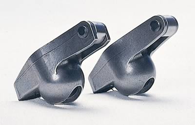
As you can see from the pics I'm using the self centering stamped roller tip rockers.
Just a dumb question,but how are these rockers considered "self centering"? I have the same ones on my engine and even when rolling it over by hand while it was still on the stand,the rollers started tracking to one side or the other.The pattern one the valve tips was good,but the rockers were so cockeyed after a few revolutions,that the push rods were rubbing in on heads.Did'nt trust it so I ended up removing the heads and installing threaded studs and guide plates.
From: Las Vegas - Just stop perpetuating myths please.
To me that 7.300" p-rod pattern looks like it never makes it to the vlv tip center. Though still far from the edge of vlv tip it seem more like side loading than the 7.050" p-rod. Just basic geometry the line of force will act at an angle to the vlv stem - unless the lifter pre-load brings it into line again.
I think your too pro-active here REEL as more than vlv stem sideloading (especially that tiny amount) is not the only cause of vlv guide wear. Are those cast iron guides? Did they have any or enough pre-lube on them on start-up and break-in? Were the guides or those two vlv stem defective? Out of tolerance from mfr? Why didnt all the other vlv guides hog-out?
Well at least this all good information for the rest of us but i kinda feel u need to take a look at it from 10 ft for a while.
Good luck and thx for sharing.
BTW u would have seen vlv float on your dyno print out that i recall u made already. Did u see an erratic nose dive with power at high RPM??
It would appear so. I followed the guidance I had at my disposal in my defense. https://www.lunatipower.com/Tech/Val...nGeometry.aspx
This is the guidance you'll find at various cam companies.
I did not add in .050 to my original prods for preload so they were .050" short based on the centered method.
I would not have imagined that I could run the rocker so close to the exhaust side of the stem. Even now I'm a bit nervous about it and will be watching stuff closely at first. Time will tell.
I believe Scott knows what he's talking about.
Hopefully I did I my part right as well.
Scott was very helpful and I enjoyed and appreciated his information. Easy guy to talk to and he's not getting anything out of this.
Besides I'm always willing to try something different it's how a guy learns. Screw it up, do it again, get it right. Nothing of great importance is lost. Kinda how hobbies go at times.
To me that 7.300" p-rod pattern looks like it never makes it to the vlv tip center. Though still far from the edge of vlv tip it seem more like side loading than the 7.050" p-rod. Just basic geometry the line of force will act at an angle to the vlv stem - unless the lifter pre-load brings it into line again.
I think your too pro-active here REEL as more than vlv stem sideloading (especially that tiny amount) is not the only cause of vlv guide wear. Are those cast iron guides? Did they have any or enough pre-lube on them on start-up and break-in? Were the guides or those two vlv stem defective? Out of tolerance from mfr? Why didnt all the other vlv guides hog-out?
Well at least this all good information for the rest of us but i kinda feel u need to take a look at it from 10 ft for a while.
Good luck and thx for sharing.
BTW u would have seen vlv float on your dyno print out that i recall u made already. Did u see an erratic nose dive with power at high RPM??
Well the goal is to try to minimize the sweep to get a more straight down push on the valve. Academically I understand that, but I still want the push in the middle as well.
I don't have 30, 40 years doing this so the nod goes to experience. My experience is still nil compared to many of these guys, so I gotta be willing to listen and learn and trust in the experience or spend lots of time and maybe money fixing my own mistakes in some situations. This is I believe is one of those times.
What Scott had to say made sense.
That dyno run started me down this path. Couple of guys said I was missing some power. I think their instincts may be correct.
After checking a couple of the obvious things and not finding the " smoking gun" I expanded my search. The smoke out the left pipe got me there a little quicker is all.
Hopefully I'm not too late.
Unfortunately I did not check the side slop on the valve guides prior to installation. So was it that way originally? Probably not. .004 is pretty noticeable.
The .015 valve spring shims are pretty beat up. This would seem to indicate loss of control on the valve spring or some bad harmonics.
I got time to find out what works. So not a big deal.
Just a dumb question,but how are these rockers considered "self centering"? I have the same ones on my engine and even when rolling it over by hand while it was still on the stand,the rollers started tracking to one side or the other.The pattern one the valve tips was good,but the rockers were so cockeyed after a few revolutions,that the push rods were rubbing in on heads.Did'nt trust it so I ended up removing the heads and installing threaded studs and guide plates.
They align the rocker on the valve tip with rails instead of using a guide plate. Look at the rocker on the left. You can see the tabs or "rails" that hang down below the roller tip. Called "rail tip" or "self aligning" rockers.
To me that 7.300" p-rod pattern looks like it never makes it to the vlv tip center. Though still far from the edge of vlv tip it seem more like side loading than the 7.050" p-rod. Just basic geometry the line of force will act at an angle to the vlv stem - unless the lifter pre-load brings it into line again.
I think your too pro-active here REEL as more than vlv stem sideloading (especially that tiny amount) is not the only cause of vlv guide wear. Are those cast iron guides? Did they have any or enough pre-lube on them on start-up and break-in? Were the guides or those two vlv stem defective? Out of tolerance from mfr? Why didnt all the other vlv guides hog-out?
Well at least this all good information for the rest of us but i kinda feel u need to take a look at it from 10 ft for a while.
Good luck and thx for sharing.
BTW u would have seen vlv float on your dyno print out that i recall u made already. Did u see an erratic nose dive with power at high RPM??
With a rocker arm you're trying to convert radial motion to linear motion. It's a compromise at best. For our sake, we can break this motion down to two basic movements; vertical and horizontal. While the motion of the rocker is pushing the valve vertically, it is also moving across the valve tip horizontally, as we can see by the "sweep" pattern. There is no significant side loading in the vertical movement. If we could just push straight down on the valve with a vertical actuator of some sort it really wouldn't matter if you were off center of the tip, the force would be linear and vertical, in line with the valve and side loading would be a non issue. What causes most of the side loading on a valve is the horizontal movement of the rocker arm across the valve tip. If you can minimize the horizontal movement (by minimizing the sweep), even if it's off center, you will do more to eliminate side loading than by trying to get the pattern centered but with a larger sweep pattern.
This diagram might help understand a little better.
When the centerline of the rocker is at 90* to the valve at mid lift, there is an equal amount of radial movement above center as there is below center and the sweep will be the absolute least it can be and have minimal side loading. If the pushrod is too short, or too long, there will be more radial movement of the rocker above, or below the mid lift point resulting in more sweep on the valve tip and an increase in side loading. If we were to move this illustration to where the roller tip was not centered on the valve tip, the dynamics and loading would still be the same, just off center some. In an absolute world one could argue that this might increase side loading some, but it is insignificant compared to poor geometry and excessive sweep.
You'll also notice the movement of the roller across the valve tip and it's position at zero lift, and at max lift. It ends up at max lift at the same place it started at zero lift...if the geometry is correct. Just watching the movement of your roller on the valve tip will give you a real quick idea of where you're at with your geometry.
It would appear so. I followed the guidance I had at my disposal in my defense. https://www.lunatipower.com/Tech/Val...nGeometry.aspx
This is the guidance you'll find at various cam companies.
I did not add in .050 to my original prods for preload so they were .050" short based on the centered method.
I would not have imagined that I could run the rocker so close to the exhaust side of the stem. Even now I'm a bit nervous about it and will be watching stuff closely at first. Time will tell.
I believe Scott knows what he's talking about.
Hopefully I did I my part right as well.
Scott was very helpful and I enjoyed and appreciated his information. Easy guy to talk to and he's not getting anything out of this.
Besides I'm always willing to try something different it's how a guy learns. Screw it up, do it again, get it right. Nothing of great importance is lost. Kinda how hobbies go at times.
Thanks Tim. It was good to talk with you as well. I understand the skepticism what with all the highly published information out there but I think you understand the concept and with that, you'll see that we went in the right direction here. Thanks for being patient with some of my explanations. I'm really more of a do-er not a teacher, but I like to try and help.
Thanks Tim. It was good to talk with you as well. I understand the skepticism what with all the highly published information out there but I think you understand the concept and with that, you'll see that we went in the right direction here. Thanks for being patient with some of my explanations. I'm really more of a do-er not a teacher, but I like to try and help.
Not so much skeptical about taking a much more experienced persons advice as I am about my ability to properly apply it to get good results. Hopefully I measured properly. That concerns me most I suppose.
From your perspective I was so far off that it's laughable. But to your credit you did not treat it that way. That I appreciate.
I'll post back the results after I get it back running again. I'll be checking the springs tomorrow.
Tim,
This industry is built on DIY guys. Giving you guys solid technical advice does nothing but strengthen the industry as far as I am concerned.
Thank you for the phone call and thank you for being a gearhead!!!
From: Las Vegas - Just stop perpetuating myths please.
Your making assumptions that minimizing the sweep will cure the problem that REEL has now or at least could have prevented it. But your assumption that minimizing sweep does not in anyway prevent it and it still occurs and still produces whatever effects it had previously. And from what i read now u agree the centered pattern creates no side loading. Also the physical mechanics of using a higher lift cam produces a larger arc for the rocker arm tip to travel which in turns increases the sweep pattern. If increasing the sweep the tiny amounts we are dealing with here causes damage to the vlv guide then using your assumptions any hi-lift cam is doomed to ruin the vlv guides. While the cure for a wide sweep pattern with a very high lift cam is a lash cap - when the vlv stem is just not wide enough and no minimizing the sweep is gonna keep the rocker tip way from the edge.
Yes i do understand your diagram but it doesnt change the fact u have no data to back up this minimizing sweep is anymore effective than a sweep accross the center of the vlv tip (ie what REEL had to begin with). It would take labratory like test with thousands of hours of run time on the same head at the different geometries including accurate parts measurements Pre and Post testing. Just because u work in an engine build shop doesnt mean u have any objective data on this at all.
Personally i dont enjoy the fact that in one post u condemn the tip centered sweep as creating side loading and now its changed to the amount of sweep thats producing the sideloading and guide wear. No i dont call that solid technical advice. U continue move your reasoning to more obscure and abstract assumptions that none of us have the equipment to verify. Show me some third party data with thousands of hours of run time to support this. U wont and there aint any. GM and the others have proprietary information im sure but most everyone else has better things to do. And so do i.
Yes im a gear head too and BTW have seen plenty of smoke and mirrors.
They align the rocker on the valve tip with rails instead of using a guide plate. Look at the rocker on the left. You can see the tabs or "rails" that hang down below the roller tip. Called "rail tip" or "self aligning" rockers.
Here is the bottom line for me on all of this "new" theory about how to set up rockers with new cams and pushrods: Until someone can produce valid technical verfication that ANY new procedure is better than data provided by millions of cam installs over too many years by Comp cams, Crane, Howards, Lunati etc.....I am going exactly with their reccommendations which is the sweeeping arc over the valve stem procedure. Common Sense/Logic would have exposed any flaws in the tried and true test LONGGGGG ago. Not buying any of this, nor would I dare mess with my valve train geometry based on theory..sorry.
Here is the bottom line for me on all of this "new" theory about how to set up rockers with new cams and pushrods: Until someone can produce valid technical verfication that ANY new procedure is better than data provided by millions of cam installs over too many years by Comp cams, Crane, Howards, Lunati etc.....I am going exactly with their reccommendations which is the sweeeping arc over the valve stem procedure. Common Sense/Logic would have exposed any flaws in the tried and true test LONGGGGG ago. Not buying any of this, nor would I dare mess with my valve train geometry based on theory..sorry.
These are cylinders #3 and #1 intake in the pictures.
This first one is #3 intake
This is #3 intake and exhaust. Exhaust on the right.
This is #1 intake.
As you can see by the witness marks on the valve stems that the roller runs directly over the center of the valve tip.
Problem is that both #1 and #3 intake valves have what seems to be excessive clearance now. Measured .003" on #3 slop at the top of the valve guide using a dial run-out mic. and then .004" of slop on #1 intake.
I measured several other valves and the rest run from .001" to .0015" of slop at that location.
So what is going on here?
I seem to remember Straub mentioning that the roller wear should favor one side of the valve stem over the other, but don't remember which side. When I assembled them I strived for centered on the stem and minimum width.
If my geometry is bad shouldn't I be seeing similar wear on all the valve guides?
I did notice that both of the intakes with the worn guides had push rods that I could see had been rubbing on the head as they passed though to the lifter. Could this be the problem?
The bottom picture shows signs of multiple roller paths....a Star...this valvetrain was not happy.
Your making assumptions that minimizing the sweep will cure the problem that REEL has now or at least could have prevented it. But your assumption that minimizing sweep does not in anyway prevent it and it still occurs and still produces whatever effects it had previously. And from what i read now u agree the centered pattern creates no side loading. Also the physical mechanics of using a higher lift cam produces a larger arc for the rocker arm tip to travel which in turns increases the sweep pattern. If increasing the sweep the tiny amounts we are dealing with here causes damage to the vlv guide then using your assumptions any hi-lift cam is doomed to ruin the vlv guides. While the cure for a wide sweep pattern with a very high lift cam is a lash cap - when the vlv stem is just not wide enough and no minimizing the sweep is gonna keep the rocker tip way from the edge.
Yes i do understand your diagram but it doesnt change the fact u have no data to back up this minimizing sweep is anymore effective than a sweep accross the center of the vlv tip (ie what REEL had to begin with). It would take labratory like test with thousands of hours of run time on the same head at the different geometries including accurate parts measurements Pre and Post testing. Just because u work in an engine build shop doesnt mean u have any objective data on this at all.
Personally i dont enjoy the fact that in one post u condemn the tip centered sweep as creating side loading and now its changed to the amount of sweep thats producing the sideloading and guide wear. No i dont call that solid technical advice. U continue move your reasoning to more obscure and abstract assumptions that none of us have the equipment to verify. Show me some third party data with thousands of hours of run time to support this. U wont and there aint any. GM and the others have proprietary information im sure but most everyone else has better things to do. And so do i.
Yes im a gear head too and BTW have seen plenty of smoke and mirrors.
Wow. Where to start.
First, lets get some facts straight. I never said a centered pattern causes no side loading. If you will read again, I said it becomes minimal and a non issue. It becomes a non issue because you've done what you can to minimize it. It will always be a factor.
Second...speaking of assumptions, lets hear what "problems" you feel REEL has now that correcting his geometry won't help eliminate (or would not have helped to prevent), and then tell me how or why it won't/wouldn't help. Using your own (lack of) logic, I could tell you that you have zero information or data to support your claims that minimizing sweep doesn't make a difference, and that you're making an equally false assumption.
I do have data that minimizing sweep is far more effective than centering the sweep. I've been doing this for 40 yrs now and experience is as relevant as any testing data. There are probably thousands of hours of spin tron testing to verify the effects of proper vs. poor valve train geometry. You say the OEM's have proprietary information but that's not true. The information is not proprietary when it comes to rocker geometry. Throughout the years many of the engineers that have worked for the OEM's have been able to pass along information such as "proper valve train geometry" and among knowledgeable engine builders this isn't a secret, but common knowledge and practice. Besides, rocker arms have been around for centuries and geometry isn't something someone "invented". Sweep and side loading are only a couple small factors affected by rocker geometry. Guide wear can also be increased by excessive harmonics created by poor geometry. There is also a loss of cam information being properly transmitted to the valve because of improper geometry. There is actually quite a list of things that improper geometry causes or contributes to and I'm sure it's all well documented somewhere, probably in hundred year old SAE papers if you want to do some digging but to say that documented information doesn't exist on all this is silly.
I'm not making this up nor did I think of it on my own. It's something I've learned throughout the years and am glad to try and pass on to those who want to learn.
Thanks for your input and I appreciate you giving me an opportunity to explain this. There's no smoke and mirrors here. It's sound engine building information and technique used by all the upper level engine builders I know and I've worked for some of the best.
Here is the bottom line for me on all of this "new" theory about how to set up rockers with new cams and pushrods: Until someone can produce valid technical verfication that ANY new procedure is better than data provided by millions of cam installs over too many years by Comp cams, Crane, Howards, Lunati etc.....I am going exactly with their reccommendations which is the sweeeping arc over the valve stem procedure. Common Sense/Logic would have exposed any flaws in the tried and true test LONGGGGG ago. Not buying any of this, nor would I dare mess with my valve train geometry based on theory..sorry.
Like I said above, it's not "new theory" or "new proceedure". The flaws of what the "catalogue" companies are telling you have been exposed for years with this information. I'm just trying to help pass it along. Some will get it, some will not.