


1971 LS5 Sending Unit Locations

Thread Starter
Racer

Joined: Apr 2015
Posts: 361
Likes: 4
From: Ohio
Can anyone tell me the location and style of the water temp sending unit? I have found 3 different types. Unthreaded post, threaded post, and a two blade style. Also, where does the oil pressure gauge line go and the oil pressure sending unit (if there is one).
Thanks!
Thanks!
Team Owner


Joined: Sep 2006
Posts: 31,283
Likes: 4,373
From: Westminster Maryland
Hi P,
For 71 the temperature sender has a 'pin' type (unthreaded) connector and is located in left side head between the 2 forward spark plugs.
For 71 bb engines the connection for the oil pressure line (no sender) is on the side/rear of the left side head.
Regards,
Alan
For 71 the temperature sender has a 'pin' type (unthreaded) connector and is located in left side head between the 2 forward spark plugs.
For 71 bb engines the connection for the oil pressure line (no sender) is on the side/rear of the left side head.
Regards,
Alan
Last edited by Alan 71; Feb 26, 2016 at 09:41 AM.
Thread Starter
Racer
Joined: Apr 2015
Posts: 361
Likes: 4
From: Ohio
Do you know what the brass piece in the picture below is? It is hard to see. It is just to the right of the dip stick below the valve cover.

Le Mans Master


Joined: Apr 2001
Posts: 5,941
Likes: 281
From: Was New Orleans but swam to Baton Rouge LA
Cruise-In IX Veteran
That is probably the CEC temp switch. It should have two prongs and be connected to a green harness. It would be for the emissions control system.
Team Owner
Joined: Sep 2006
Posts: 31,283
Likes: 4,373
From: Westminster Maryland
Hi Sig,
You posted while I was trying to figure out if that was a 70 or 71!
Hi P,
If this is in fact a 71 it's likely that that's another temperature sensor/switch that is part of the CEC emissions system that 71 cars had. Combined Emission Control.
I'm more familiar with sb engines and that's near the location for that sensor on the 350 engines.
It typically has a single 2 spade connector.
Might that be what you're seeing.
Regards,
Alan
Hi, I looked again and that's not a 71 car in the pic, it's a 70. That confused me.
Here's the switch on a sb engine… I'd think it would be the same switch on your bb.
Last edited by Alan 71; Feb 26, 2016 at 10:11 AM.

Advanced

Joined: Oct 2010
Posts: 80
Likes: 2
From: near Nuremberg Bavaria
Yes it is - but in '70/'71 it usually goes by the name TCS System (Transmission Controlled Spark).
Last edited by QuRace; Feb 26, 2016 at 10:57 AM.
Le Mans Master
Joined: Apr 2001
Posts: 5,941
Likes: 281
From: Was New Orleans but swam to Baton Rouge LA
Cruise-In IX Veteran
Corvette Stories
The Best of Corvette for Corvette Enthusiasts

Top 10 Most Expensive Corvettes Ever Sold on Bring A Trailer
Brett Foote
10 Things Every Corvette Owner Needs (2026 Edition)
Michael S. Palmer
8 Most "Only Corvette Owners Understand" Quirks and Problems
Pouria Savadkouei
10 Reasons the C6 Z06 is Still A Performance Benchmark After 20 Years
Joe Kucinski
How Much Horsepower Every Corvette Engine "LOST" in 1972
Joe Kucinski
Top 10 DOs and DON'Ts for Protecting Your Convertible Top!
Michael S. Palmer
Top 10 Most Explosive Corvettes Ever Made: Power-to-Weight Ratio Ranked!
Joe Kucinski
150 hp to 1,250 hp: Every Corvette Generation Compared by the Specs That Matter
Joe Kucinski
8 Coolest Corvette Pace Cars (and Replicas) of All Time
Verdad Gallardo

Team Owner
Joined: Sep 2006
Posts: 31,283
Likes: 4,373
From: Westminster Maryland
Hi P,
In the picture the lower 'pin' sensor would have been typical for your 71 and the connector in the harness should be for that 'pin'.
The system we're talking about for 71 is called Combined Emission Control.
It has different hardware than the TCS systems that was used for 1970 and 1972.
For the 1971 CEC system the hardware is:
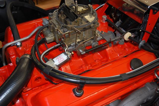
A solenoid mounted on the left front of the carburetor with an electrical and vacuum connections.
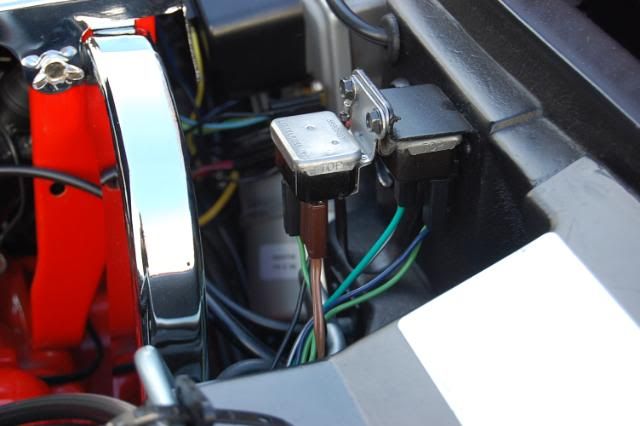
2 relays mounted on the firewall to the left of the engine. A Reversing Relay, and a Delay Timer Relay.
The temperature sensor/switch in the right side head.
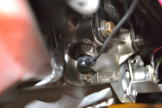
A switch mounted in the transmission case that, for 71 cars w/4-speed transmissions, monitors when the transmission is in 3rd and 4th gears. On 4-speed cars the shifter shaft activates the switch while on automatic cars I believe it's the fluid pressure.
The engine harness contains the electrical wire ring and connections for all these parts. Except for a short jumper lead from the harness to the temperature sensor in the right side head.
All 71 model year cars left St.Louis with this system.
Regards,
Alan
CEC Solenoid.
Reversing Relay and Delay Timer Relay.
Sensor for 3rd & 4th in transmission in a 4-speed equipped car.
In the picture the lower 'pin' sensor would have been typical for your 71 and the connector in the harness should be for that 'pin'.
The system we're talking about for 71 is called Combined Emission Control.
It has different hardware than the TCS systems that was used for 1970 and 1972.
For the 1971 CEC system the hardware is:
A solenoid mounted on the left front of the carburetor with an electrical and vacuum connections.
2 relays mounted on the firewall to the left of the engine. A Reversing Relay, and a Delay Timer Relay.
The temperature sensor/switch in the right side head.
A switch mounted in the transmission case that, for 71 cars w/4-speed transmissions, monitors when the transmission is in 3rd and 4th gears. On 4-speed cars the shifter shaft activates the switch while on automatic cars I believe it's the fluid pressure.
The engine harness contains the electrical wire ring and connections for all these parts. Except for a short jumper lead from the harness to the temperature sensor in the right side head.
All 71 model year cars left St.Louis with this system.
Regards,
Alan
CEC Solenoid.
Reversing Relay and Delay Timer Relay.
Sensor for 3rd & 4th in transmission in a 4-speed equipped car.
Last edited by Alan 71; Feb 26, 2016 at 03:31 PM.
Team Owner

Joined: Jan 2006
Posts: 37,637
Likes: 3,118
From: Crossville TN
The 'single pin' temp gauge sender is on the LEFT side head between cyl #1 and #3. The 'two pin' TCS temp switch is on the RIGHT side head between cyl #6 and #8.
The TCS sender DOES have a wire on it that runs from one of the pins to the other. [One terminal is for 'temp too low'; the other is for 'temp too high'. And either can send the same signal to the TCS system, as they might occur.]
The TCS sender DOES have a wire on it that runs from one of the pins to the other. [One terminal is for 'temp too low'; the other is for 'temp too high'. And either can send the same signal to the TCS system, as they might occur.]
Last edited by 7T1vette; Feb 26, 2016 at 05:03 PM.
Team Owner
Joined: Sep 2006
Posts: 31,283
Likes: 4,373
From: Westminster Maryland
Hi P,
To clarify…
The sender in the LEFT side head is for the center gauge cluster temperature gauge only. It is a pin connector in 1971.
The sensor in the RIGHT side head that you asked about using the picture is part of the 71 ONLY CEC system which I described, the TCS system was used in 1970 and 1972. The sender served the same function for the 3 years.
I mention this again because if you look for TCS info it won't help you, you need to look for CEC information.
Regards,
Alan
GM issued a specific manual for the 71 CEC system (and maybe for other years too) that went to the dealership service departments. The manual is 27 pages.
If you're thinking about getting the CEC operating, (if it's not), on your car the manual will be a big help. They're available on the bay pretty regularly at reasonable prices.
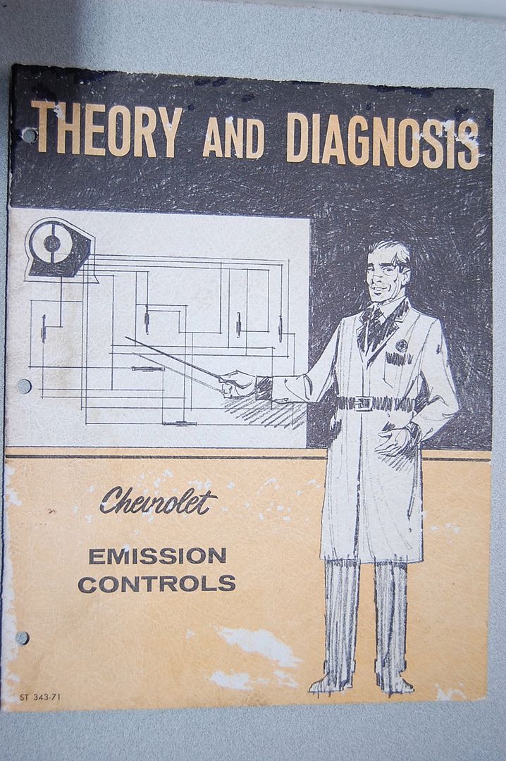
This is the sort of info it contains and how it's presented.


To clarify…
The sender in the LEFT side head is for the center gauge cluster temperature gauge only. It is a pin connector in 1971.
The sensor in the RIGHT side head that you asked about using the picture is part of the 71 ONLY CEC system which I described, the TCS system was used in 1970 and 1972. The sender served the same function for the 3 years.
I mention this again because if you look for TCS info it won't help you, you need to look for CEC information.
Regards,
Alan
GM issued a specific manual for the 71 CEC system (and maybe for other years too) that went to the dealership service departments. The manual is 27 pages.
If you're thinking about getting the CEC operating, (if it's not), on your car the manual will be a big help. They're available on the bay pretty regularly at reasonable prices.
This is the sort of info it contains and how it's presented.
Last edited by Alan 71; Feb 26, 2016 at 06:04 PM.
Thread Starter
Racer
Joined: Apr 2015
Posts: 361
Likes: 4
From: Ohio
Hi P,
For 71 the temperature sender has a 'pin' type (unthreaded) connector and is located in left side head between the 2 forward spark plugs.
For 71 bb engines the connection for the oil pressure line (no sender) is on the side/rear of the left side head.
Regards,
Alan
For 71 the temperature sender has a 'pin' type (unthreaded) connector and is located in left side head between the 2 forward spark plugs.
For 71 bb engines the connection for the oil pressure line (no sender) is on the side/rear of the left side head.
Regards,
Alan

Last edited by Pikeslayer; Feb 29, 2016 at 09:29 AM.
Team Owner
Joined: Sep 2006
Posts: 31,283
Likes: 4,373
From: Westminster Maryland
Hi P,
I said head by mistake, sorry!, it's in the block just below the head and above the oil filter.
If you have a 71 AIM look at UPC LS5, Sheet A5. This page shows the proper parts and their assembly for the oil line to the gauge.
If you don't have the AIM go to the Paragon Corvette Reproductions site and look at the page for the 454 oil line connection parts. There's a nice drawing showing all the parts in place.
The plugged fitting in your picture is the first piece of what's needed for the oil line. You see that elbow in the drawings.
Good Luck!
Regards,
Alan