When you click on links to various merchants on this site and make a purchase, this can result in this site earning a commission. Affiliate programs and affiliations include, but are not limited to, the eBay Partner Network.
I have been absent from the forum for quite a while, health issues have kept me nailed down and unable to work on my little 72. I'm going to try and pick up some of the pieces of my build that I was forced to lay down. I'm trying to build a fuse panel with the necessary relays and circuit breakers. I have some questions for those who know their way around the wiring aspect of our vetts. My first question is: Is it necessary to have a circuit breaker along with a fuse and relay or is acceptable to just have one or the other (a fuse or a circuit breaker)? My second question is around a wiring diagram I have created, could you please review for any errors I have made? Richard and DUB have helped tremendously in the past. If you guys are still monitoring the forum, please have a look. I'm going to try and put this together this weekend if I can keep my strength up. Thanks
From: Loud, Raw and Dangerous 1968 327 4S in Southern California
Nice detailed schematic. Both CB's and fuses do the same thing just have different mechanical reset/replace requirements when tripped or blown. You may want to put some lower rating CB's or fuses to protect any branch circuits that are lower current rating than the 30 and 40 amp circuit breakers you have. For example you would not want to allow 29 amps thru a wiring circuit designed for 10 amps.
Redvette2
Last edited by Redvette2; Jul 17, 2019 at 12:53 PM.
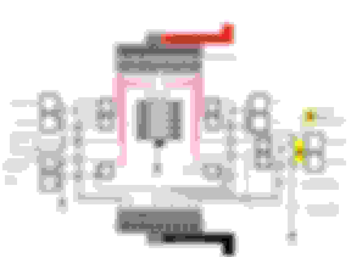
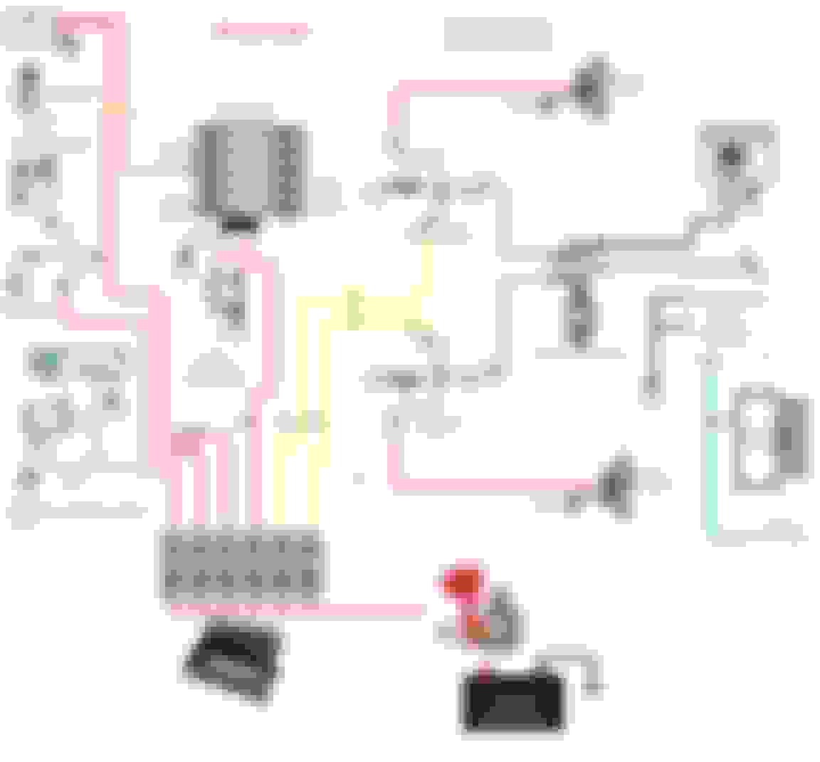
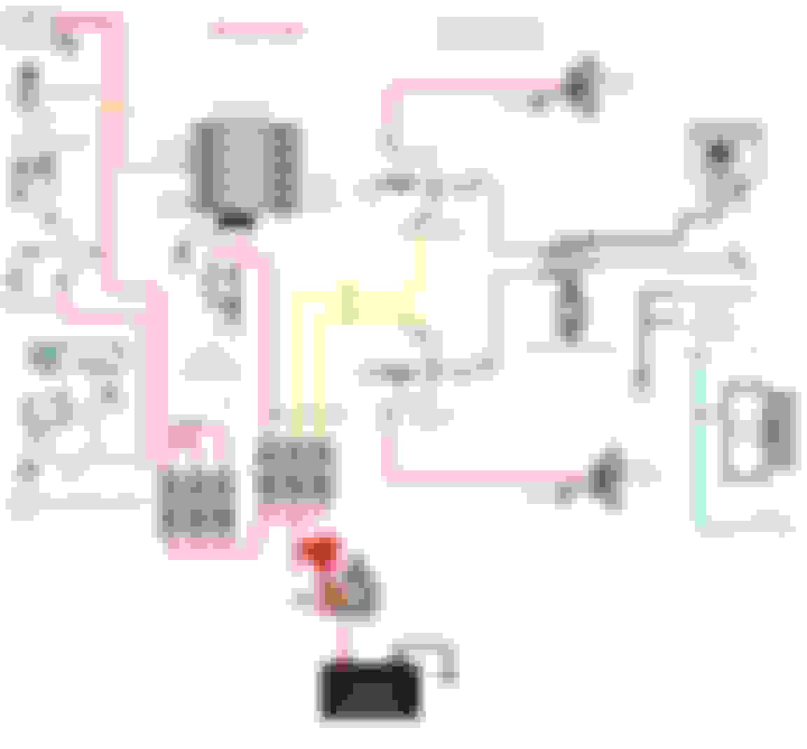
I made so many mistakes in the first diagram that I have scrapped the entire plan. I'm using a Be Cool Radiator/ Dual Fan Kit with their relays for both the fans and AC. I reworked my diagram to identify their wire coloring and relays. The AC portion of the drawing was very difficult to find online and I hope I have it right. I have also included my vacuum pump, electric fuel pump and MSD in the diagram. My motor is not stock, however, it is a number's matching block. It was stroked and tends to run a little warm, therefore I want to run both fans with or without the AC on. I will allow the temp sensor to trigger them. I also plan to have a bypass just in case --- I have edited the diagram (7-31-19) to capture some of the recent changes. Please look over the diagram for errors or alterations that I might need to make. Thanks.
Edited 8-3-19
Last edited by mitch.1972vette; Aug 3, 2019 at 07:08 PM.
I'm planning to run a 10 awg primary wire from the circuit breaker to the vacuum pump relay and fuel pump relay's and headlight relays but what size wire do I need from the relay to the actual pumps or devices? I guess I really need help understanding what the needs are for each device. The Vacuum pump calls for a 30 amp relay, the MSD is a 30 amp fuse, the Fuel pump is a 30 amp relay, the fans are 40 amp relay's each (I don't know what the fuse size is). The headlights are covered under Richard's wiring harness, no worries there - he has also included the fuse/fuse holders with his kit. I'm struggling to sort through the wire sizes and some of the other fuses. I just don't have a very clear understanding of my needs. Any help offered is very much appreciated.
I have had such a dreadful time coming up with the Be Cool Wiring instructions that I want to post them to help the next guy who finds themselves in my position. Please note, this is for Bee Cool and I'm not sure how much can be shared with other types of set-ups but I suppose they could be used by many. This actually belongs to Be Cool:
From: Loud, Raw and Dangerous 1968 327 4S in Southern California
Here is a link to help you out. I like to size the short runs at 120% of wire rating (a few feet) and the longer ones (5-10 ft+) at 150% of rating. For example if the max current draw is 30 amps I would size a short run wire gauge for 36 amps (1.20 * 30A = 36A). This is because many CB's and Fuses have designed in trip points 20% higher than rating. Then you have ambient temperatures and peak currents that factor in as well.
From: Loud, Raw and Dangerous 1968 327 4S in Southern California
There is a wide range of wire temperature ratings and it mostly has to do with the insulation integrity surrounding the wire itself. I have seen the insulation melted and dripping off a wire because it was routed too close to the exhaust. A quality wire manufacturer would have the rating code imprinted on the wire itself or on the spool.
Here is a sample rating chart at the end of this post...this chart is mainly for house and building wire codes. I would suspect there are similar charts for automotive wire.
Edit Update: Found this but no charts:
The three main types of PVC automotive wire are:
GPT: used for general circuit wiring and rated to 80 degrees Celsius
TWP: lead-free, thin-wall automotive wire rated to 105 degrees Celsius
HDT: heavy-wall automotive wiring rated to 80 degrees Celsius
PVC is insulation is extruded and created by heating PVC and then extruding it through a die on the stranding. This insulation can be melted with a heat source, changing the form.
The three most common types of cross-linked automotive wire are:
GXL: thin wall, most common type, works with most standard automotive connectors, rated to 125 degrees Celsius
There is a wide range of wire temperature ratings and it mostly has to do with the insulation integrity surrounding the wire itself. I have seen the insulation melted and dripping off a wire because it was routed too close to the exhaust. A quality wire manufacturer would have the rating code imprinted on the wire itself or on the spool.
Here is a sample rating chart...this chart is mainly for house and building wire codes. I would suspect there are similar charts for automotive wire.
Redvette2
For under the hood- SXL is what I usually use- easily found in different colors and gauges -even Summit racing sells this stuff. There are TXL (thinnest) and the GXL which is in between the thicker SXL- all are rated to 125�C (about 260�F) There's also a SGX -thickest but that's usually for battery cable.
Current rating for wire is done at an ambient temp of 70�F and unbundled. So bundling AND underhood defiantly move to a larger correct type of wire.
From: Loud, Raw and Dangerous 1968 327 4S in Southern California
Originally Posted by Richard454
For under the hood- SXL is what I usually use- easily found in different colors and gauges -even Summit racing sells this stuff. There are TXL (thinnest) and the GXL which is in between the thicker SXL- all are rated to 125�C (about 260�F) There's also a SGX -thickest but that's usually for battery cable.
Current rating for wire is done at an ambient temp of 70�F and unbundled. So bundling AND underhood defiantly move to a larger correct type of wire.
Richard
Great information, I will keep this for reference as I rewire. I have already removed or replaced about 10 feet of various PO wiring.
Redvette2
Last edited by Redvette2; Jul 27, 2019 at 04:57 AM.
Great information, I will keep this for reference as I rewire. I have already removed and/or replaced about 10 feet of various PO wiring.
Redvette2
Good deal-
The other thing to look out for is the dreaded "CCA"- or "Copper Coated Aluminum"- some try to sell it as copper but when you solder it and bend it a few times it'll break. With all the Chinease knock-offs out there - Id' check the wire just to make sure!!
Mitch
Something you may consider adding to you wiring system.
I run a oil pressure piloted switch in my fan system , to prevent the fans drawing when starting engine when it’s at operating temperature. The switch operates at 20PSI
I wired mine to latch the relay ,so the fans run even with momentary oil pressure drop, during hard Corning.
bfit
Mitch
Something you may consider adding to you wiring system.
I run a oil pressure piloted switch in my fan system , to prevent the fans drawing when starting engine when it�s at operating temperature. The switch operates at 20PSI
I wired mine to latch the relay ,so the fans run even with momentary oil pressure drop, during hard Corning.
bfit
That's a good idea-
I'm using a Hella- timed relay- to soft start my AC and fans set about 10 seconds (programmable from 1 sec to 900sec) after the car starts-
WOW, really good information! Richard has already helped me with an inertia switch, the oil switch (timed or pressure) are really good ideas. Would you guys be willing to share a link where I might purchase one at a reasonable price? I'm good at locating the most expensive stuff - really good...lol...
I had originally hoped to jump from my starter power lug to my circuit breaker buss and auxiliary fuse block with a #4 power wire (only about 3 ft.). That way I could conveniently slip this little breaker in between the two. I�m just not sure how safe that would be. Are you guys running two power wires from your battery? One going to your starter and the other to your auxiliary power supply? Adding-up the amount of voltage going through my circuit breakers leads me to believe I will need about 220 amps for my auxiliary fuse block. Will this breaker be sufficient if I mount it near the battery?
From: Loud, Raw and Dangerous 1968 327 4S in Southern California
Seems like way overkill for the rating of the large circuit breaker. Going so big might defeat the purpose of protecting your car wiring from a high short current. Your running current likely would be a fraction of the sum total of the individual branch breakers. If you were drawing even close to 220 amps your battery would go dead as I believe most stock alternators are typically 50 to 100 amps capable. For example...my house main AC circuit breaker is 175 amps but the total of all of the individual branch breakers is 700 amps. Let's see what the experts say!?
Redvette2
Last edited by Redvette2; Aug 2, 2019 at 03:56 AM.
Reason: Kan't spel/added info
Something just doesn't seem right with my way of thinking but I don't know enough about the electrical system to figure it out. With both fans running (they will be intermittent with the temp sensor), the fuel pump running, the MSD on and the vacuum pump running (the vacuum will be intermittent)....CRAP!!!!! Ahhhhh - Unfortunately, I just don't know how many amps the accessories will be pulling in a normal cycling state or how many it will pull under full demand.. I'm completely open to any ideas. I'm a bit - lost..
Think of the battery as your savings account and the alternator as your income.
If there is a short on the alternator - it'll be a puff of smoke and quit working- and since the electronics /accessories are protected by fuses - you'll just have a torched alternator.
The battery - on the other hand- has a very low internal resistance- when shorted can deliver enormous currents and if it continues long enough the battery itself will overheat and explode.
I would just put a fuse at the battery and call it a day.
This is what I am using for my car...a little overkill- but I have a lot of high draw electrics and a custom high output alternator- 0/1 cable from Alternator to battery and battery to starter- 4GU to the front of the car (headlights/horns/electric headlights/twin spal fans) and 4 GU behind the dash-for running 12 injectors/12 coils/power windows/locks/ ECU / Vintage Air / heated seats/electric exhaust cut-outs/ electric parking brake..)
Also running Electric AC compressor and Electric Power Steering Motor-
Last edited by Richard454; Aug 2, 2019 at 09:46 AM.