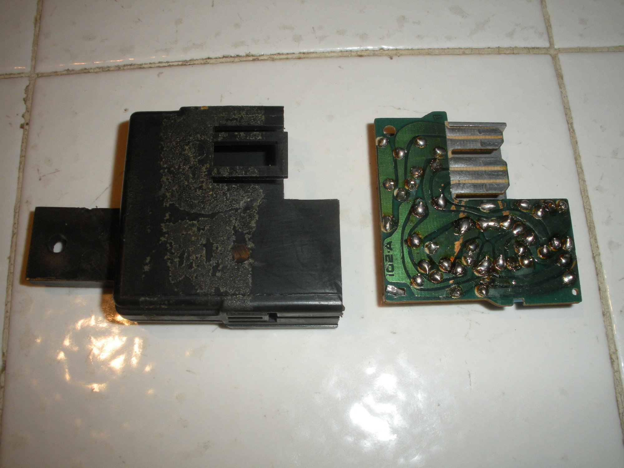
Interior light delay module / relay FIX.. 85-87
#21
Safety Car


I had my dashpad off the other year and think I could see it taped on top of a wire bundle near the top. Unfortunately I couldn't get to it through the top.
The way I've read the easiest way if you cannot bend into a pretzel is take the passenger seat and hush panel out and lay on the floor to get to it. When I do mine that's what I'm planning to do. Take out the breadbox and come in through the front then put a flat panel back in in place of the breadbox.
If you need the interior lights on in the interim, just turn them on via turning the headlight switch to turn them on. The door switches to release the convertible top (or the back glass I think) require the interior lights to be on for them to work.
#22
I had my dashpad off the other year and think I could see it taped on top of a wire bundle near the top. Unfortunately I couldn't get to it through the top.
The way I've read the easiest way if you cannot bend into a pretzel is take the passenger seat and hush panel out and lay on the floor to get to it. When I do mine that's what I'm planning to do. Take out the breadbox and come in through the front then put a flat panel back in in place of the breadbox.
If you need the interior lights on in the interim, just turn them on via turning the headlight switch to turn them on. The door switches to release the convertible top (or the back glass I think) require the interior lights to be on for them to work.
The way I've read the easiest way if you cannot bend into a pretzel is take the passenger seat and hush panel out and lay on the floor to get to it. When I do mine that's what I'm planning to do. Take out the breadbox and come in through the front then put a flat panel back in in place of the breadbox.
If you need the interior lights on in the interim, just turn them on via turning the headlight switch to turn them on. The door switches to release the convertible top (or the back glass I think) require the interior lights to be on for them to work.
#23
Good evening Korvette
I have the problem of interior lights that do not come on when I open the door right or left,
but they light up with the headlight **** turning it to the left, so the bulbs are not burned,
the delay switch is easy to find?
and if not we can remove it and connect all the white wires together ??
is that ok Korvette ??
thank you for your help,
greetings and merry christmas
Didier
Bonsoir Korvette
J'ai le problème des lumières intérieures qui ne s'allument plus quand j'ouvre la porte droite ou gauche,
mais elles s'allument avec le bouton des phares en le tournant vers la gauche, donc les ampoules sont pas grillées,
le commutateur de retard est facile à trouver?
et sinon on peut le supprimer et relier tous les fils blancs ensemble??
c'est bien ça Korvette??
merci pour ton aide,
salutations et joyeux Noël
Didier
#24
[DEVIS = korvette4u; 1549978428] combien de C4 sont-ils confrontés à ce problème? AUCUNE lumière intérieure… ne réussit pas à éteindre ni même à s'allumer? 85-87
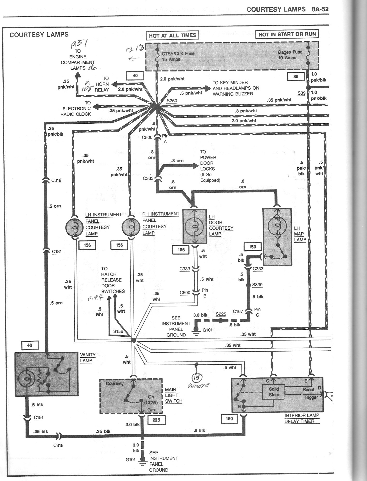
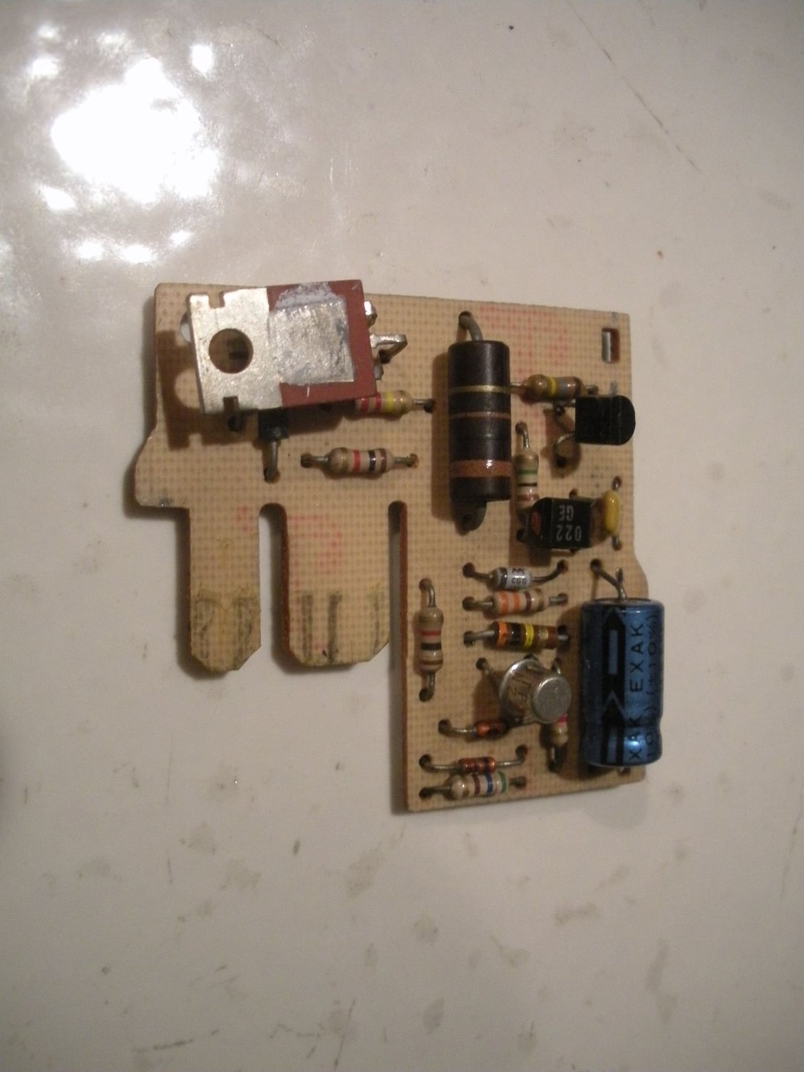
Problème: pièce n ° 10098435 Description du module de temporisation: environ 2 "carrés.
solution temporaire ne devrait pas être utilisé comme" votre voiture, vous voulez que vous
voulez " broches sur le module: codes de couleur peuvent varier avec les années (consultez votre code de couleur exact pour votre année )
A = film blanc à toutes les lampes
B = noir est la terre, court-circuitant blanc à noir allumera les lumières
C = rose / blanc est à 12 volts du fusible Ctsy / Clk qui est chaud tout le temps
D = 2 fils blancs évalués des interrupteurs de porte. les interrupteurs se ferment lorsque la porte est ouverte et en masse sur les fils blancs en fonction de la porte ouverte.
E = est le signal de réinitialisation utilisé par le module de temporisation pour éteindre le module lorsque vous vous êtes arrêté le contact. alors les lumières s'éteignent. vous n'avez pas ce fil.
Vous avez besoin d'un relais pouvant être manipulé 5 ampères à 12 volts. unipolaire unipolaire relais automatique ouvert Atlas NC502 ou équiv.
Que faire: le
primaire / du bobine 12 volts relais Nécessite. Quel est le rose / blanc.
l'autre côté de la bobine nécessiterait 2 fils blancs des interrupteurs de porte. Lorsque la porte est ouverte, l'un des fils blancs fournit une terre pour les 12 volts à travers la bobine. La bobine fermée Les contacts secondaires
Les relais secondaires.
le fil blanc épais provient de toutes les ampoules,
le fil noir est le sol. Parce que le réel est maintenant fermé. the black and the black are now
lorsque vous fermez la porte, l'interrupteur de la porte s'ouvre, le circuit est vraiment hors tension et le fil noir n'est plus.
Cet arrangement éteindra et allumera la lumière seulement lorsque la porte sera ouverte ou fermée. il n'y aura aucun délai après la fermeture de la porte.
ce sujet a été discuté avec d'autres membres du forum quand j'avais demander. c'est une bonne information pour ceux qui désirent ... fonctionne pour moi: ***** :: *****: [/ QUOTE]
Bonjour korvette4u
Pouvez-vous me donner le schéma de câblage de cet interrupteur,
merci d'avance
Didier
#25
Quelqu'un peut -il me donner le schéma de câblage du module de retard d'éclairage intérieur
merci d'avance
Didier
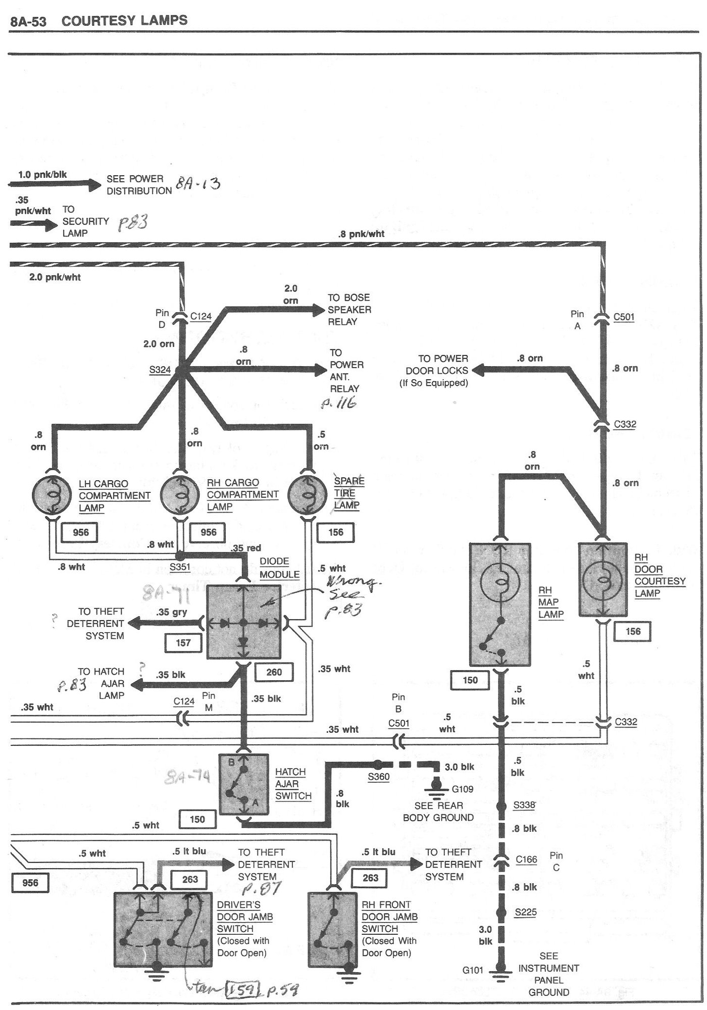
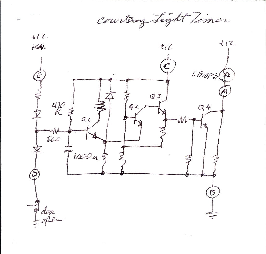
Can someone give me the wiring diagram of the indoor lighting delay module
thank you in advance
Didier
merci d'avance
Didier
Can someone give me the wiring diagram of the indoor lighting delay module
thank you in advance
Didier
The following users liked this post:
didou24 (03-27-2019)
#29
Merci Hot rod roy
Je viens d'imprimer ce schéma électrique et je vais faire ça,
relier les trois fils blancs et c'est ok??
as-tu déjà démonté la boîte à pain, est-ce difficile??
en attendant je te dis un grand merci,
Thank you Hot rod roy
I just printed this wiring diagram and I'm going to do that,
connect the three white wires and that's ok ??
have you already dismantled the bread box, is it difficult??
in the meantime I say a big thank you,
#30
Safety Car


This seems to work okay, but it does put more current through the door switches, which may shorten their life. As expected, there is no delay function.
It is not necessary to dismantle the bread box. The module is accessible by removing the "hush panel" above the passengers feet. I replaced the Q1 transistor in my module for the repair. I used a 2N2222 transistor.
I have friends in Jonquieres. Is that far from you?

Have you already dismantled the bread box, is it difficult??
I have friends in Jonquieres. Is that far from you?

#31
Merci pour ta réponse qui va bien m'aider,
tes amis à Jonquières sont à 600 km de chez moi,
bonne journée et à bientôt surement,
salutations de France,
Didier
Thank you for your answer that will help me,
your friends in Jonquières are 600 km from my home,
good day and see you soon,
greetings from France,
Didier
tes amis à Jonquières sont à 600 km de chez moi,
bonne journée et à bientôt surement,
salutations de France,
Didier
Thank you for your answer that will help me,
your friends in Jonquières are 600 km from my home,
good day and see you soon,
greetings from France,
Didier
#32
Comment savoir quelle pièce acheter car il y a 3 modèles différents, ou alors relier les 3 fils blancs,
il y en a un aussi qui fait juste interrupteur sans le timer, tu connait la référence et ou l'acheter?
merci et à bientôt
Bonjour de FRANCE

#33
Drifting


Member Since: Jun 2018
Location: Brisbane Australia
Posts: 1,397
Received 283 Likes
on
219 Posts
C4 of Year Finalist (performance mods) 2019
#34
Comment voulez vous dire relier les fils blancs,
sur le schéma électrique pouvez vous me montrer comment et où les relier,
merci Greg de la FRANCE
Friendly
Didier
Hello Greg
How do you mean connecting the white wires,
on the electrical diagram can you show me how and where to connect them,
thank you Greg from FRANCE
Friendly
Didier
#35
Drifting


Member Since: Jun 2018
Location: Brisbane Australia
Posts: 1,397
Received 283 Likes
on
219 Posts
C4 of Year Finalist (performance mods) 2019
Bonjour Greg
Comment voulez vous dire relier les fils blancs,
sur le schéma électrique pouvez vous me montrer comment et où les relier,
merci Greg de la FRANCE
Friendly
Didier
Hello Greg
How do you mean connecting the white wires,
on the electrical diagram can you show me how and where to connect them,
thank you Greg from FRANCE
Friendly
Didier
You should be watching the F1 instead of working on your corvette today. 🏎🏁 Quite an enjoyable race.
Yes I think I can help (but it wasn’t me that posted the suggestion). All you have to do is join all the white wires together. It’s the wires connected to terminal A and terminal D. I have marked up the hand drawn drawing to shown the terminals I mean.
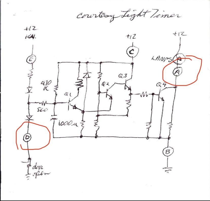
Join A and D
Alternatively you can usually fix these modals by replacing the power Transistor Q4
Anyway hope this helps and also I hope things are getting back to normal in France. I love your country but I haven’t been there for twenty years now.
#36
Merci Greg pour la réponse,
aujourd'hui promenade en Corvette à un rassemblement annuel où j'ai vu beaucoup de voitures Américaines et des très belles,
le schéma électrique ne me dis pas comment faire car un gars du forum dit qu'il y a 3 fils blancs et toi me dit d'en relier deux,
en France le Covid se calme mais on a peur que ça revienne,
vous au USA c'est compliqué, ta santé et ta famille vont bien?
si tu reviens en France tu viendras chez moi:à votre santé:
merci Greg
Thanks Greg for the answer,
today ride in Corvette to an annual gathering where I saw a lot of American cars and some very beautiful ones,
the electrical diagram does not tell me how to do it because a guy from the forum says that there are 3 white wires and you tell me to connect two,
in France the Covid calms down but we are afraid that it will come back,
you in the USA it's complicated, your health and your family are well?
if you come back to France you will come to my house
Thanks Greg
aujourd'hui promenade en Corvette à un rassemblement annuel où j'ai vu beaucoup de voitures Américaines et des très belles,
le schéma électrique ne me dis pas comment faire car un gars du forum dit qu'il y a 3 fils blancs et toi me dit d'en relier deux,
en France le Covid se calme mais on a peur que ça revienne,
vous au USA c'est compliqué, ta santé et ta famille vont bien?
si tu reviens en France tu viendras chez moi:à votre santé:
merci Greg

Thanks Greg for the answer,
today ride in Corvette to an annual gathering where I saw a lot of American cars and some very beautiful ones,
the electrical diagram does not tell me how to do it because a guy from the forum says that there are 3 white wires and you tell me to connect two,
in France the Covid calms down but we are afraid that it will come back,
you in the USA it's complicated, your health and your family are well?
if you come back to France you will come to my house
Thanks Greg
#37
Drifting


Member Since: Jun 2018
Location: Brisbane Australia
Posts: 1,397
Received 283 Likes
on
219 Posts
C4 of Year Finalist (performance mods) 2019
Good morning Didier
Just connect all the wires on terminal A to all the wires on terminal D. To be honest I can’t remember how many there are. You could actually make a jumper cable the goes between the two terminals (with the module disconnected/removed).
I’m in Australia not the US so we are in a pretty good place with COVID-19. In the state of Queensland (where I live) we have had no new cases for a long time but we are still working from home and are concerned about a second wave. Our friend in the US are who I’m worried about, I’m not sure there are any effective strategies in place over there. I think they are going to make Italy and Spain look like a party in comparison.
Sorry I have only replied in English as I do not speak French. Not many people study European languages in Australia anymore because there is not much chance to practice them.
Lastly thank you for your offer of a visit to your house. My wife and I traveled extensively before we had kids and spent about four weeks in France in a camper van. We loved it and plan to return one day.
Regards Greg
Last edited by GregMartin; 07-05-2020 at 07:09 PM.
#38
Good morning Didier
Just connect all the wires on terminal A to all the wires on terminal D. To be honest I can’t remember how many there are. You could actually make a jumper cable the goes between the two terminals (with the module disconnected/removed).
I’m in Australia not the US so we are in a pretty good place with COVID-19. In the state of Queensland (where I live) we have had no new cases for a long time but we are still working from home and are concerned about a second wave. Our friend in the US are who I’m worried about, I’m not sure there are any effective strategies in place over there. I think they are going to make Italy and Spain look like a party in comparison.
Sorry I have only replied in English as I do not speak French. Not many people study European languages in Australia anymore because there is not much chance to practice them.
Lastly thank you for your offer of a visit to your house. My wife and I traveled extensively before we had kids and spent about four weeks in France in a camper van. We loved it and plan to return one day.
Regards Greg
Just connect all the wires on terminal A to all the wires on terminal D. To be honest I can’t remember how many there are. You could actually make a jumper cable the goes between the two terminals (with the module disconnected/removed).
I’m in Australia not the US so we are in a pretty good place with COVID-19. In the state of Queensland (where I live) we have had no new cases for a long time but we are still working from home and are concerned about a second wave. Our friend in the US are who I’m worried about, I’m not sure there are any effective strategies in place over there. I think they are going to make Italy and Spain look like a party in comparison.
Sorry I have only replied in English as I do not speak French. Not many people study European languages in Australia anymore because there is not much chance to practice them.
Lastly thank you for your offer of a visit to your house. My wife and I traveled extensively before we had kids and spent about four weeks in France in a camper van. We loved it and plan to return one day.
Regards Greg
J'ai regardé cet après midi mais je n'ai pas trouvé le courtesy light timer,
peut-être est il trop haut et je ne le vois pas,
ou alors y a t'il eu un autre montage sans le timer?
par contre en bougeant les fil quand j'ai remis la trappe les lumières se sont allumées,
j'en déduis que c'est un problème de terre,
bonne soirée Greg

Hello Greg
I looked this afternoon but I didn't find the courtesy light timer,
maybe it's too high and I can't see it,
or was there another editing without the timer?
by moving the wires when I put the hatch back on, the lights went on,
I deduce that it is a ground problem,
good evening Greg
#39
Drifting


Member Since: Jun 2018
Location: Brisbane Australia
Posts: 1,397
Received 283 Likes
on
219 Posts
C4 of Year Finalist (performance mods) 2019
Bonjour Greg
J'ai regardé cet après midi mais je n'ai pas trouvé le courtesy light timer,
peut-être est il trop haut et je ne le vois pas,
ou alors y a t'il eu un autre montage sans le timer?
par contre en bougeant les fil quand j'ai remis la trappe les lumières se sont allumées,
j'en déduis que c'est un problème de terre,
bonne soirée Greg
Hello Greg
I looked this afternoon but I didn't find the courtesy light timer,
maybe it's too high and I can't see it,
or was there another editing without the timer?
by moving the wires when I put the hatch back on, the lights went on,
I deduce that it is a ground problem,
good evening Greg
J'ai regardé cet après midi mais je n'ai pas trouvé le courtesy light timer,
peut-être est il trop haut et je ne le vois pas,
ou alors y a t'il eu un autre montage sans le timer?
par contre en bougeant les fil quand j'ai remis la trappe les lumières se sont allumées,
j'en déduis que c'est un problème de terre,
bonne soirée Greg

Hello Greg
I looked this afternoon but I didn't find the courtesy light timer,
maybe it's too high and I can't see it,
or was there another editing without the timer?
by moving the wires when I put the hatch back on, the lights went on,
I deduce that it is a ground problem,
good evening Greg


