When you click on links to various merchants on this site and make a purchase, this can result in this site earning a commission. Affiliate programs and affiliations include, but are not limited to, the eBay Partner Network.
Yeah, I'm going to plastigage the main bearings before I put it back together. I don't expect to find a problem, but better safe than sorry.
If your crank hasn't been ground undersize, checking bearing clearance with plastigage "usually" doesn't reveal too tight bearings or a lack of clearance, Just the opposite, it usually reveals too loose, or excessive clearance, bearings. But fear not, main (and rod) bearings come in "std", 0.0005" os and 0.001" os, so you can pretty much tailor each bearing journal for optimal clearances. Performance bearings are available individually so this isn't as difficult (or expensive) as it may seem.
From: Las Vegas - Just stop perpetuating myths please.
Originally Posted by C4ProjectCar
Thanks for the calculations and advice! I'll put the heads back on with the .051" gaskets as soon as I can, probably next week sometime.
Had to get this to u before u install the heads and compress the gaskets. Your gonna want the heads off when u measure the brg clearances. Just in case a piston ring popps out.
Yes plastigauge has its querwks. But if your not a trained machinist trying to get a bore gauge squared up to read accuratly to 0.0001" can be error likely. And expensive to buy. Even much more expensive if used improperly. Myself i dont own or use a dial bore gauge as u really need one thats accurate to 0.0001".
Ok sorry for the bother but i just couldnt watch/read a piston moving too far down the hole while your measuring clearances.
Hopefully I won't have to replace any bearings with oversize bearings, but it's good to know that's an option. What would you consider too loose for a new engine? .0025" or so?
Thanks for the tip to leave the heads off. Is there anything in particular I have to do to keep a ring from popping out, or should I just be careful not to let the piston get too close to either end of the cylinder?
Unfortunately I'm really busy right now, but I'm hoping to measure the clearances and reinstall the heads by next weekend.
I'm FINALLY getting around to doing some more work on my new engine.
I plastigaged the front main bearing, and got about .020". I took the rod bolts out of the #4 rod to plastigage a rod bearing, but couldn't get the bearing cap off without excessive force and didn't want to risk damaging something, as I have no reason to suspect the bearing tolerances are off.
However, when I went to put the rod bolt back in I realized I didn't know the torque spec. In order to guesstimate, I put a socket on a rod bolt I hadn't touched, incrementing my torque wrench by 5 lb.-ft. at a time until it turned, which happened at 85 lb-ft. That seems incredibly high for rod bolts to me.
On that sheet, it says that the 3/8" 8740 rod bolts should be torqued to 45 lb.-ft. Although I'm not positive that the bolts I linked are my exact rod bolts, I know by measuring and by the markings on the head that they are ARP 3/8" 8740 bolts.
I put the bolts I had taken out back in at 45 lb.-ft. Should I loosen and retighten the other bolts to the same, or should I tighten them all to the 80 lb.-ft. that it seems they were originally tightened to?
From: Las Vegas - Just stop perpetuating myths please.
Main bearing clearance should be 0.0025 or less. Are u sure u had 0.020" on #1 cap??? That cant be right or you got the wrong bearings in there.
Maybe the 85ft-lbs explains why the rod cap wont come off. 45ft-lbs sounds right to me. Now something thats hard to find out is if your torque wrench is in calibration unless u have access to a calibrated load cell somewhere. Thats why i bought a new set of beam wrenches (craftsman) and checked their cal at work. Beam wrenches are usually correct out of the box and stay cal'd unless u gave them a big drop sometime. And i can use them to look at break-away torque also (not that it accurate at all). Beam wrenches are very repeatable in applying torque also just can be difficult to use in some locations and it easy to exceed the desired torque value. Contact scat on how to get'm (rods) apart.
I think now your committed and need to check all the bearing clearances and torques - rod and mains. BTW over torquing to 85ftlbs could well have damaged them/bolts (pulls the metal into the elastic region and distorts the shape/strength) - again u need to contact the mfr. And when u say u "put the rod bolt back in" didnt make sense at first as i have never used that type of rod/bolt combo so my advice is limited (i only used the pressed in bolts where the nuts come off).
I think u will be rewarded having checked all these clearances and torques.
Sorry, I left out a "0" on accident. .0020" is what it was.
I use the click type now, but I've used the beam type before. Just by feel, I can tell my click type wrench could not be off by more than a small amount.
I found out that there's a tool to separate the two halves, but given that I have limited time to get this back together I don't want to have to track one down.
I'll call ARP and SCAT to be sure, but I don't believe the bolts are damaged. They're made out of ARP2000 which has a tensile strength of 220,000 PSI, even higher than the 8740 steel that ARP head studs are made out of. Then again, the thread count and bolt thickness both affect things.
I'm not even sure the bolts were actually that tight. I'm not sure the reason, but it seems to me that bolts that have been sitting for a while kind of "set" and take more force to undo.
Yeah, each one just has a single bolt that connects the two halves. Definitely different than the rods in my old engine.
I've been through the whole process of checking clearances and all that on my old engine, and I'd rather not repeat it if I don't have to.
Thanks for the input.
Last edited by C4ProjectCar; Mar 9, 2015 at 11:44 PM.
Update:
I ordered new ARP nuts for my heads, but as I was getting ready to put them on I noticed a couple of things. First, about five of the washers are slightly bent. They are bent toward the center, perhaps rolled would be a better term, I believe because the nuts that were used did not have a flat spot on their bottom the size of the washer to evenly distribute the pressure, so the pressure was concentrated toward the inside of the washer. Also, about 5 of the bolt holes on the heads seemed to be deformed -- it looks like the washers actually crushed the aluminum somewhat.
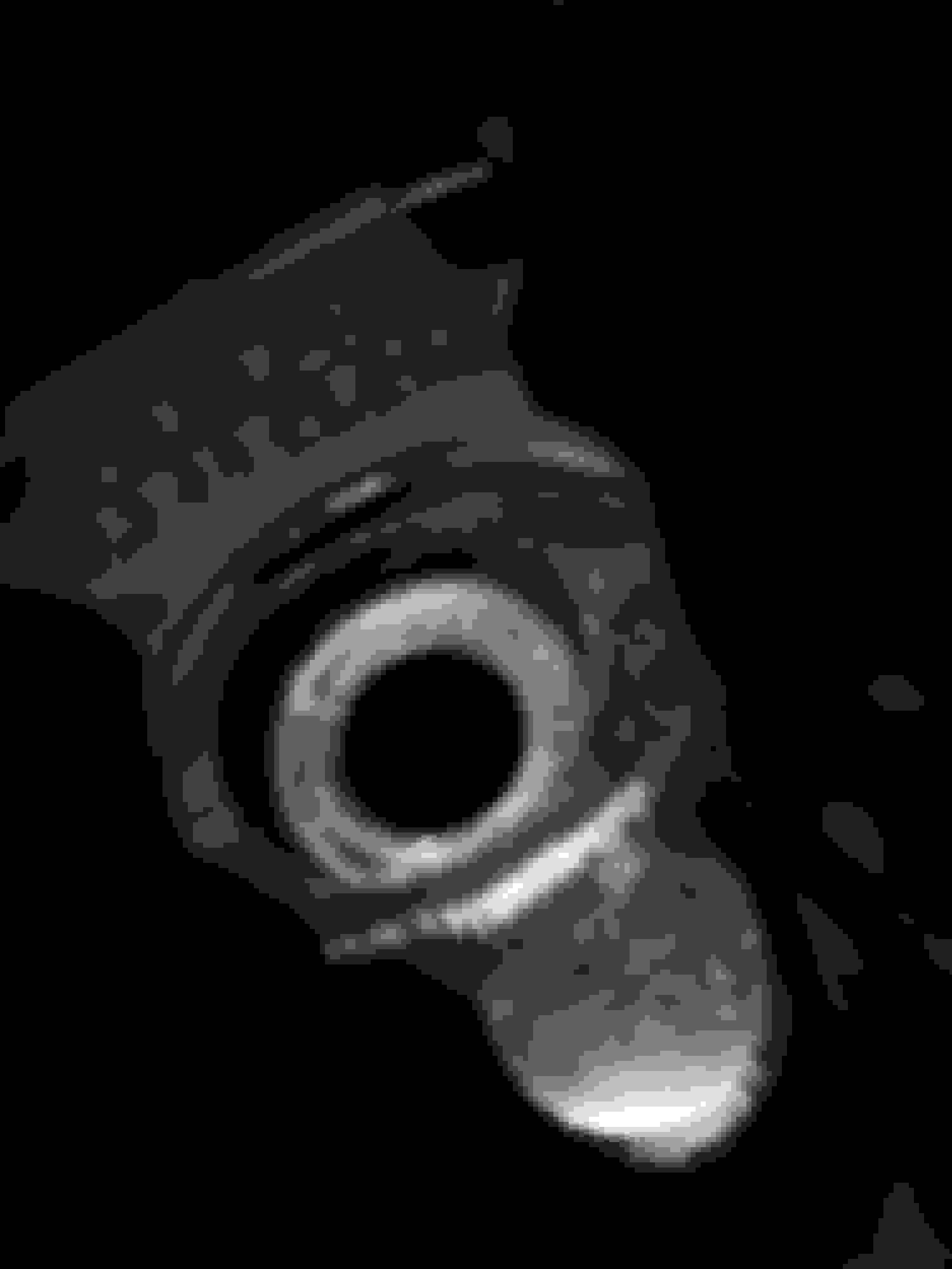
I'm replacing all of the washers that appear to be crushed in, but I'm concerned about the head. From the outside of the area for the nut, the material depresses downward, then raises upward to a lip around the hole. It's tough to describe, so here are a few pictures that hopefully make it a little more clear.
It's hard to see, but the light makes it a bit easier in this picture. Notice the lip around the hole?
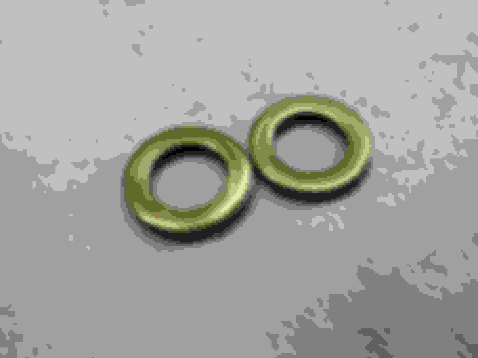
Damaged washer on the left. See how it rolls inward, whereas the one on the right is flat?
The way I see it, the washer could have been caused by two things: either 80 lb.-ft. is too tight (ARP and other research told me 80 lb.-ft.), my torque wrench is off, or as I think is likely the nuts were the wrong nuts for this.
My biggest question though is this: do you think I should just put it back together with the new washers, or do I need to take it to a machine shop to have those deformed parts of the head machined flat?
Thanks for all the help, guys. Hopefully I'll have this back together soon so I can start on the actual swap.
Last edited by C4ProjectCar; Mar 16, 2015 at 02:05 PM.
Unfortunately, it seems few are still following my thread, but I'll keep updating it in case someone finds something I post useful in the future.
I took my head by a machine shop, where at the machinist's recommendation I had the faces that the nuts pull up against machined flat again.
While there, I also found out that my washers are fairly insubstantial for head washers. To be safe, I ordered 34 new washers, which are larger in both outside diameter and thickness.
With all new nuts and washers, I don't see what could possibly go wrong (knock on wood), so hopefully I can get the heads on and start installing the rockers soon.
As to your rod bolts; they should be torgued, then the nuts removed, threads cleaned, checked for burrs then using the lubricant of your choice (or red locktite, my preference) the nuts should be reinstalled and then tightened to the recommended torque; this two step helps insure that the shoulders of the bolt are fully seated into / onto the rod;
The heads? yes, if those (presumably) hardened extra thick steel washers are as deformed as you indicate, I'd definitely consider having the washer seating surface in the head "kissed" by an end mill and trued up....something wasn't right from the get go to see deformation like that...I'd also considered having those seat area's "zyglowed" to check for cracking allowing the seat area to deform (something common back in the bad old days with cast iron heads that had been on and off a few times too many, especially when head washer's weren't used) .
Finally, were those washers actually hardened? most hardened washers intended for use on heads, high pressure steam fittings etc, besides being extra thick with both surfaces machined, are almost always heat treated with a black finish...those washers look more like someone's idea of a head washer.
I had the machine shop mill those damaged faces and I'll be picking the head up today.
My rods don't have nuts (the bolt just screws directly into the rod), but I'm assuming the same procedure applies. I'll pull and reinstall those bolts.
I'm nearly certain that the deformation was a result of improper washers being used with improper nuts. The new washers and nuts are both significantly more substantial.
From: Las Vegas - Just stop perpetuating myths please.
Sorry for the late reply C4 but working 12 hr shifts i dont have any time for internet. And u have some unique/uncommon problems there that i would be just guessing at for a fix. I think u did the right thing and worked with your machinist there. BTW its helpful to get to know the local machine shops isnt it as when need thier expertise u know where to go and where not to go.
Sorry for the late reply C4 but working 12 hr shifts i dont have any time for internet. And u have some unique/uncommon problems there that i would be just guessing at for a fix. I think u did the right thing and worked with your machinist there. BTW its helpful to get to know the local machine shops isnt it as when need thier expertise u know where to go and where not to go.
How did all your brg clearances measure out?
No problem man, I appreciate any help I can get (especially from someone that busy).
It's definitely nice to become acquainted with people that do stuff like this for a living.
Due to time restrictions I can't measure them all, but so far I've measured two rod bearings and one main bearing (I plan to measure another).
The main bearing measured at approximately 2 thousandths, as did the rod bearings.
I just got the heads back on and the lifters and spider plate reinstalled. I was going to try to put the rockers on too, but it turns out the pushrods are bent. 4 are severely bent (~1/16" deflection) 7 others are slightly bent (just enough so they roll with an irregular tempo across a sheet of glass) and the remaining 5 are just bent enough to see light shining underneath them on glass. So I guess I'm getting new pushrods.
I tested the pushrods for proper length, even though I couldn't install them. With the lifter on the base circle, the tip of the rocker contacted the valve stem tip about 1/4"-1/3" from the inside edge, which from what I've read means that they're the correct length. Does that sound right to you?
Any suggestions for pushrods? I can't get 3/8" because of the size of the guide plates on the heads. The pushrods that were in it were Sealed Power RP-3262, which are pretty cheap.
Last edited by C4ProjectCar; Mar 21, 2015 at 12:33 AM.
From: Las Vegas - Just stop perpetuating myths please.
Hmmm, how did the p-rods get bent? I think the heads were assembled when u got the engine correct? Someone had to overtorque the heck out of the p-rods to do that. Or maybe those p-rods were from the engine before rebuild and were bent by previous owner. Bent p-rods and damaged head bolt washers/faces means some very heavy hands were on that assembly.
Seems like u have/had a lot of issues in the top end but nothing yet in the bottom end. Unless that was severely overtorqued also like u suspected. Good thing your retorquing everything and inspecting the brgs to.
Ok for p-rods u need hardened p-rods with your guide plates or the guide plates will eat them up. With your cam i dont think u need really thick dia p-rods if u get good quality chrome moly p-rods. As for length just get a P-rod checker from ProForm or Moroso: http://www.summitracing.com/parts/pro-66789/overview/. Cheap and very easy to use. Just install over the rocker stud and measure gap between p-rod and rocker (p-rod to short) or rocker and vlv tip (p-rod to long). Add or subtract difference from stock p-rod length to order new p-rods correct length.
Yes the rocker tip needs to travel over the center of the vlv stem tip. Anything too close to the edge will cause side loading and ruin the vlv guide. But with a street cam & lift it aint rocket science and close is good enough - just keep it away from the front and rear edges of vlv stem.
Good your take'n the time for this or your bargain motor would have been short lived.
The heads were assembled, but only a few of the pushrods were in the engine. The rockers weren't installed and the pushrods looked a little scratched, so I think the pushrods were from the seller, not his machine shop. But yeah, the top end has been a nightmare from the very beginning, having to chisel through the Right Stuff sealant to get the intake base off.
Since the rods I had put the rocker tip fairly close to the center of the valve stem, should I be good with the same length, or is measuring it with that tool a must?
As far as the connecting rods go, I don't believe they were actually overtightened. I loosened each of them a quarter turn, then retightened them to 45 lb.-ft. which took about a quarter turn for each.
From: Las Vegas - Just stop perpetuating myths please.
If u have a contact patch over the center of the vlv stem tip then no u dont need anything. Just remember u need the hardend p-rods and stronger chro-mo p-rods aint much more $.
I think u are using higher ratio roller rockers though and u need to check clearance with the retainer and rocker stud. A unbent paper clip works well for this. Heres something from crane cams to help: http://www.cranecams.com/uploads/instructions/425e_.pdf.
Hope this helps and good luck. Your getting closer here to finishing.
Here are a couple pictures of the contact patch--one with the valve closed, and one at approximately max lift. Since I have hydraulic lifters, "max lift" isn't really max lift, as the plunger inside the lifter is depressed. However, I thought it would give a decent reference point, keeping in mind that in reality the contact patch at max lift will be shifted to the left.
By the way, this was with the rockers installed to zero lash plus half a turn of lifter preload.
It looks fine to my inexperienced eye, but I thought I'd run it by you to make sure.
I wasn't able to check those clearances today but I'll do so tomorrow.
From: Las Vegas - Just stop perpetuating myths please.
Ok theres probably tech tips on cam mfrs w/s that can explain this better than me - but ill give it a try here. The rocker tip makes a sweep across the vlv stem tip that starts at the near side of tip on base circle. Then it moves outward due arc of travel and reach max across vlv tip to the far side at mid-lift. Then it starts to return towards the near side of vlv tip at full lift. U need to think of it as a travel of an arc.
So what common is to use machinists blue marker on the vlv tip and observe the patch pattern after a couple of rotations. Some say they can see this with black felt marker too - up to u.
I looks like in the 1st pic the rocker is closer to the near side than i feel comfortable with - but pix can lie.
I suspect the pushrod length is not optimum. If the heads are still off, measure the length of a valve and the length of a pushrod. post the measurements. I didn't see the reason for the bent pushrods yet. Did you disassemble the heads? Bent pushrods can be caused by a stuck (galled) valve stem/guide.
BEFORE you jump to conclusions, consider that those massive springs are pressing the piston inside the hydraulic lifter down into the lifter body and that since the engine is in a static condition (not running) there is NO oil pressure pumping the piston up in opposition to the valve spring;
So the photo's are at best, misleading; So I would:
Either order and use some light weight valve springs designed Just for checking valve train geometry and then visually check where the rocker arm tip is in relation to the valve stem tip; I know this is a major pain in the **** because you have to remove the rocker arm, remove the existing valve spring, install the checker spring, remove the checker spring, reinstall the valve springs, reinstall the rocker arm, etc....
So let me suggest a much simpler alternative; get an old lifter, let's call it the "test lifter" take it apart, place a series of small washers in the lifter bore, reinstall the piston...which now can't be moved down into the bore by the valve spring pressure (no matter how great) ...install the test lifter. rotate the engine and NOW observe the rocker arm roller travel across the valve stem tip.
This will give you a much more accurate idea of the valve train geometry when the engine is actually running.
Designer Imagines A Corvette That Looks More Like a Corvette Than the Corvette
Slideshow: A Jaguar designer's personal project imagines what a modern front-engined Corvette might look like if Chevrolet revisited the golden age of the Stingray.