When you click on links to various merchants on this site and make a purchase, this can result in this site earning a commission. Affiliate programs and affiliations include, but are not limited to, the eBay Partner Network.
The LT1 intake has nothing to do with anything related to the ignition. Sounds like you should have asked MI Motorsports where to mount it. Or build your own harness like I suggested back around post #17 or so, and then put the coil, wherever YOU want it.
Okay it is odd. The TPIS Big Mouth TPI base I have has three holes on the front, but the factory GM 1991 TPI Base on the car currently only has two. One fitting that feeds the throttle body and then the heater core with coolant, and then the fitting for the fan switch.
What do yall think about drilling and tapping the rear of the manifold for a heater outlet fitting to send coolant from the rear of the manifold to the heater core?
Anyone know the thread on the coolant temperature fan switch? 3/8" NPT?
Sure! Do it. Front, rear....it doesn't matter. It's like mounting the coil; personal preference. Which ever suits your fancy. Either places will work just fine.
All of the threaded holes to water, are NPT. The obviously vary in size depending on the hole.
Sure! Do it. Front, rear....it doesn't matter. It's like mounting the coil; personal preference. Which ever suits your fancy. Either places will work just fine.
All of the threaded holes to water, are NPT. The obviously vary in size depending on the hole.
Yes, they obviously vary in size, and yes I know it is an NPT pipe thread. I don't know exactly which size it is, but I need to drill and pipe tap somewhere for it, which is why I'm asking what size it is.
Regarding pulling coolant for the heater core from the front or rear. If it doesn't matter much, then what about just using a T fitting from the current two hoses that I'll have coming off of the front, and sending some coolant to the heater core? That is the easiest in terms of labor and routing hoses. My concern is poor flow and poor cooling performance.
If had known what I know now, when I was in the machine shop I would have drilled and tapped all four corners of the manifold, and likely sent the two rear hoses directly to the remote thermostat, and then run one of the front hoses to the heater core and the other front hose to the high pressure line that goes to the high pressure recovery tank, or alternatively taken a single hose from the front to a T then one arm of the T to the heater core, one arm to the high pressure recovery tank, and then at the other unused front corner drilled and tapped a hole (of unknown NPT thread size, still waiting on an actually helpful response) for the coolant temperature fan switch.
Also curious if anyone knows the size of this heater hose? Trying to get a T for it. Maybe 1/2" or 3/8 ID?
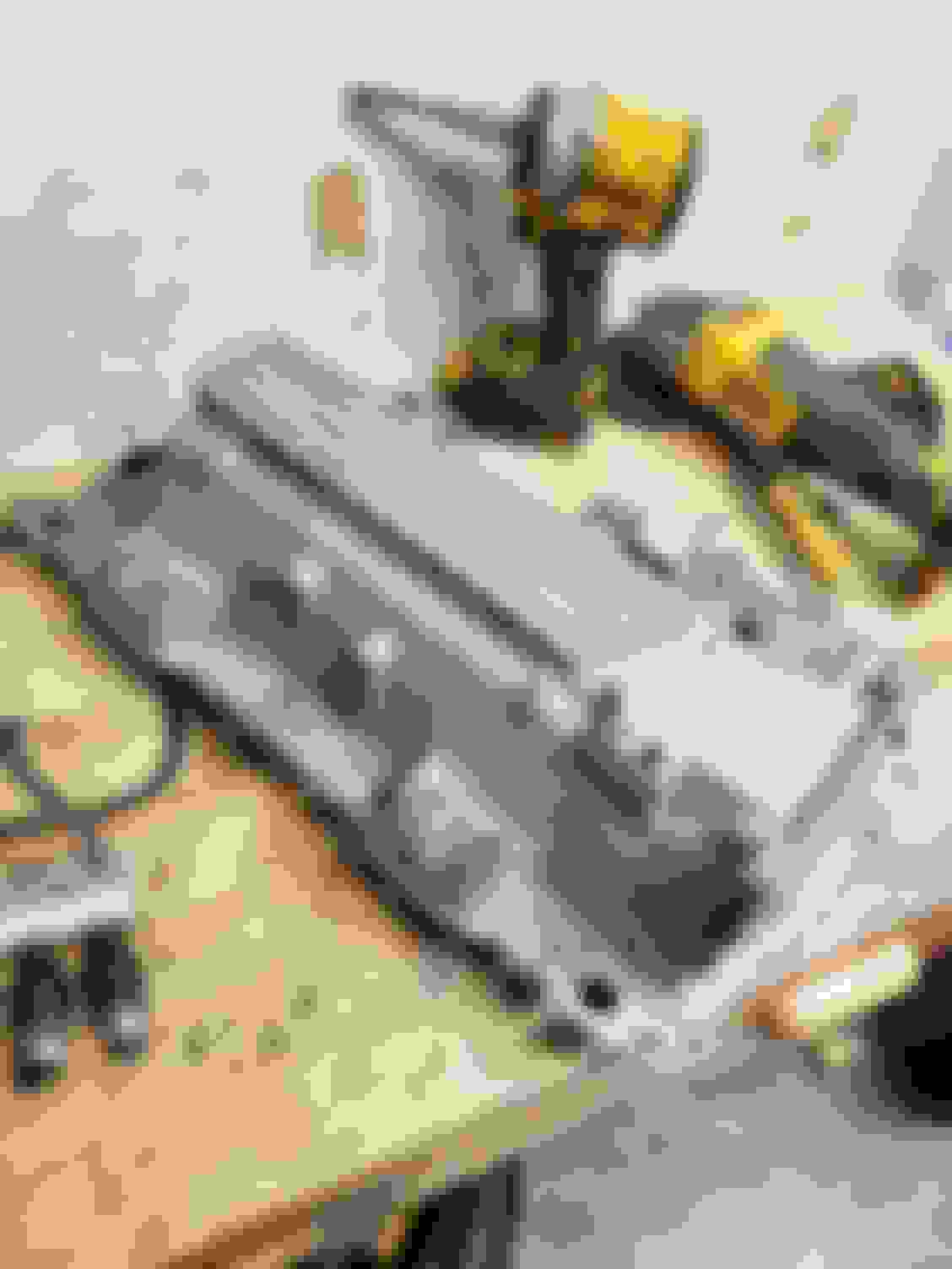
Also here is the front of my TPIS big mouth intake, not sure what the third larger NPT pipe thread hole is for.
Last edited by yakmastermax; 04-21-2023 at 04:55 PM.
Okay going back to my friend's father's shop today. He is being extraordinarily gracious.
I am trying to decide between the following different setups for the coolant stuff:
Setup 1:
Coolant outlets at both front corners, and one outlet at rear passenger corner. Pair of hoses from front corners goes to remote thermostat. Single 5/8" hose from passenger rear corner goes to a 5/8" x 1/2" x 5/8" Tee. 5/8" arm feeds heater core, which returns to water pump. 1/2" arm feeds the high pressure reservoir tank via the hose in the picture above. This is the "steam air pocket" line that is at the passenger rear TPI base from the factory.
My concerns with this setup is that coolant at the rear of the passenger head goes to the heater core, then back to the water pump, which then I believe just gets pumped back into the block again? Seems like a good way for the coolant at the rear of the motor to stay on the hotter side? Also I don't like that it is asymmetrical in that there isn't an outlet at the driver rear. An additional tee and outlet at the driver rear could fix that, but that means even more flow from the rear of the heads into the heater core then back to the water pump then back into the block and that just doesn't seem right...
Setup 2:
Coolant outlets at all 4 corners. Both rear outlets go direct to remote thermostat, these would be a pair of 3/4" hoses. Front outlets are 5/8" hoses, both are sent to a 5/8" x 5/8" x 5/8" Tee then into a single 5/8" hose, which is then sent to another T, this one being a 5/8" x 1/2" x 5/8" Tee with the 5/8" outlet arm feeding the heater core, and the other arm, the 1/2" one, feeding the small hose which goes to the high pressure reservoir.
I think on principle this one will provide the motor with superior cooling over the factory configuration as it increases coolant flow at the rear of the motor. It will be a bit messy in terms of hoses though, mainly because the two rear hoses have to run up to the front of the motor.
Not sure which route to go. Looking for suggestions!
2020 Corvette of the Year Finalist (appearance mods)
C4 of Year Winner (appearance mods) 2019
Originally Posted by yakmastermax
Also here is the front of my TPIS big mouth intake, not sure what the third larger NPT pipe thread hole is for.
On mine, a barbed nipple screws in that hole. Onto that, a 3/4" radiator hose feeds down behind the A/C mount. IIRC, it might go to that 3-way "T" for the oil cooler -- if so equipped. If not, maybe it gets plugged?
As for the other size hose, maybe 5/8" though perspective is hard to make a guess. Kinda looks bigger than 1/2".
Made some good progress today. Gonna start taking apart the TPI tomorrow. Also the 1991 finally passed emissions. Advanced base timing to 14 degrees plus more injector cleaner got the hydrocarbons below the threshold, so now I can move on with modding the car!
My friend's father let me use his shop again. I need to get him a present. He has a collection of die cast cars. I'm thinking a die cast C4? Any suggestions for a nice one?
Using his nice AC Miller Aluminum Tig setup I added material to three out of 4 of the heater hose fitting locations, including the one that didn't really have much thread thickness.
Then I punched holes where the coolant passages open up to, in preparation for threading for 1/2" NPT. I used an endmill to plunge mill drill these holes as I wanted them normal to the top of the motor, which meant hitting the manifold flange at an angle.
After milling out the hole to tap, I used the mill to clean them up a bit. Then I tapped them 1/2" NPT. There are now 1/2" NPT holes to all four corners of the manifold.
I also had to clearance the large of the EGR ports to fit the small cap distributor which is a chinesium clone of an MSD 8366 small cap distributor. Part of this clearance work meant cutting away the old bolt hole for the EGR diaphragm or block off plate in my case. I welded the remaining bolt hole closed, then drilled an tapped a new 5/16"-18 hole for the EGR block off plate. I got some nice stainless hex cap screws in 5/16"-18 from ACE hardware to use with the block off plates. I'll need to modify the larger of the EGR block off plate gaskets, but that is easy to do.
I also drilled and tapped the distributor angled spacer shim adapter. I am going to cut a custom gasket as well to go between the angled spacer adapter and the manifold deck to ensure no leaks. Of course all the hardware is getting thread sealant during final install. I used a pair of 1/4"-28 bolts to secure the angled distributor adapter spacer at the front end, and I used some nice small 10-32 hex cap screws to secure the angled adapter at the rear. I clearance hole drilled the angled adapter itself, and drilled and tapped the manifold. This was all done at an angle so the bolts and screws clamp the angled adapter to the manifold properly. Came out pretty slick I think! Hopefully doesn't leak. Also looks like the boss I welded on then drilled and tapped for the distributor hold down fork bolt is lined up properly!
My biggest concern right now is the throttle body, throttle cable bracket, and the front driver coolant outlet fitting.
I don't have an LT1 throttle body. I was going to reuse my L98 one. I do have the LT1 throttle cable bracket. I'm not sure how this is going to work. Anyone got any ideas? I'm also concerned that the 1/2" NPT by 5/8" hose barb fitting that I have on the front drivers side of the manifold is going to interfere with whatever I end up doing for the throttle body and throttle cables and bracket. I might end up plugging this fitting. What do yall think about that? In that case the thermostat is fed from the two 3/4" hoses coming from the two fittings at the rear, and the heater core and the high pressure reservoir will be fed from the 5/8" hose coming from the passenger side front fitting, with the drivers side front fitting capped off to make clearance for whatever the solution is for the throttle body, cable, and bracket.
Any ideas on this?
Oh I also did a little bit of porting and widening of the LT1 intake ports to match the L98 gasket width. No big deal! Also was able to hit the manifold with the bead blaster. My buddy's father has a nice big blasting cabinet. His shop is incredible.
Super excited. Hoping to make race day in 6 days!
Brake fluid and brake pads arrive mid week. Wheel bearings arrive tomorrow. I go the new U joints today.
Last edited by yakmastermax; 04-23-2023 at 02:08 AM.
Can you share more information on how you did your throttle body, cable, and cable bracket modification for your LT1 intake manifold conversion to L98 shortblock ZF6 install?
You said you used the TPI bracket but in the picture it looks like you used the LT1 bracket? Did you combine the two brackets with welding?
Did you use a TPI throttle body or L98 throttle body?
Thanks for any assistance!
Originally Posted by Space387
There is one last challenge with the intake, and that is throttle linkage. I have a 6spd so there is no TV cable to deal with, for those with a 700R4 the bracket wont be too much different you will just have to shorten that cable too. For me I used the TPI bracket and cut it to be a bit smaller. I also relocated one of the tabs inboard about 1/2 an inch to align the cables better with the pulley. TPI bracket on the left, LT1 on the right. The tab seen on the top left corner of the TPI was cut off at the bend and welded roughly 1/2 in closer to the cables. The remaining bracket
Both cables need to be shortened to make this fit. The large loop for cruise control will also not fit due to the reduced distance between the bracket and the throttle. To shorten the throttle cable you can either get under the dash and add spacers to the pedal to take up the slack or cut the cable. I opted for the latter and used a single 20Gau barrel connector without the plastic casing. The crimp tool I used is for Metri-pack terminals giving me a squared connector when done. Im sure any good crimping tool will work just be sure to test it well before driving. To accommodate for the cruise control I used a 20 Gau eyelet connector. After cutting off the loop and some of the plastic sheathing I measured and cut the wire to length, slid the eyelet over it and tack welded the wire tip to prevent fraying. DO NOT CRIMP THE EYELET. The cruise control does not have as much travel as the gas pedal and will bind or damage the solenoid if you force it to follow the throttle plate. to complete the fit I had to bend the eyelet so the wire passed under the post
.
I am wondering how I should go about doing the PCV system. The plan is to use 1996 LT4 composite valve covers (similar to 1993-1996 LT1 valve covers). I believe these covers don't have holes in them for the PCV system except for one small hole on just one of them? The drivers or passenger side? What about the rest of the hose routing? Any suggestions? Can I mimic the factory LT1 PCV system using my L98 throttle body? Was there a special provision in the LT1 heads that allowed air flow between each valve cover and the lifter valley? A provision that my 113 heads don't have?
I think I found the information for tbe thread pitch for the coolant temperature sensor switch CTS that mounts to the front side of the TPI intake base. I think it is 3/8"-18 NPT
I am gonna drill and tap the remote thermostat housing for that guy.
Okay, MAT Sensor, or AIT, same thing, manifold air temp or air intake temp sensor. On my 1991 L98 the sensor is located on the underside of the plenum towards the rear, and being a speed density car this sensor is critical to proper function.
The LT1 intake has no provision for it.
What to do? Drill and tap a spot for it on the intake? If so, where? I could buy a 92-93 LT1 intake duct that has a spot for the AIT MAT sensor on the side of the duct, but that is sorta expensive. Can I maybe just modify my current L98 intake duct to have a spot for the AIT MAT sensor and elongate my current plug lead so it reaches.
Also still need help with the PCV setup. Not sure how to run it. I am hoping to use the LT1 valve covers I got. Suggestions?
I took another look at the throttle cable bracket. Current plan is to combine the LT1 bracket with the L98 bracket by welding. I might lose cruise control. How to shorten the throttle cable? What is the safe and correct way? Can I use electrical crimp connectors and crimp the braided steel cable?
Thanks all!
Also I painted the converted manifold, and starting tearing into the old TPI. Really hoping my idea for the fuel lines works.
Last edited by yakmastermax; 04-25-2023 at 10:35 AM.
Making progress! Took two days off of work to hopefully get this done. Hoping to race the car on Saturday but we shall see.
Got the TPI manifold off. Here are some pics of the rear china wall area. I can't tell 100% if this was where the oil was leaking from? Sorta looks like it? Not sure. Also previous owner used RTV as thread sealant it seems on the intake manifold to head bolts. Don't know if that is advisable but I am going to use permatex white colored high temp thread sealant myself.
Had to clearance the manifold a little bit for one of the manifold to cylinder head bolts. Also had to shift a few of the holes I drilled. They were just a bit off. Also shaved some washers to fit.
I also gasket matched and ported the LT1 intake manifold to the TPI gaskets. This is the before showing that the LT1 ports are taller than the TPI ports but that the TPI ports are wider:
Here is the after once I opened up the TPI gasket at the top and bottom of the port, and opened up the LT1 manifold port width:
As you can see in the below pictures, the 113 cylinder head intake ports are pretty small compared to what I have opened the gasket and LT1 intake manifold ports up to.
I decided to gasket match and lightly port the 113 cylinder heads while on the car. Lots of tape, and going to run a vacuum while I do it. Will be careful to absolutely minimize any aluminum dust from getting into the motor. Finished cylinders 2,4,6,8 last night. 1,3,5,7 today, then valve lash, then going to install the manifold! What do yall think, 10rwhp?
Last edited by yakmastermax; 04-27-2023 at 11:26 AM.
I am rather confident a most minimal amount of aluminum dust might have made it into the motor. No actual aluminum chips or slices as I only used sanding bit, so really just dust!
I think the motor should be fine! 140k miles on it anyway lol
Worked on the car for 18 hours yesterday, and another 6 today. Only stopped to eat and hit the parts store.
Bad news, I missed the race
Good news, got it running and driving, and it pulls decent. Feels healthier for sure than the TPI intake did especially above 4k rpm. I only did a few pulls as I don't want run it hard yet because it still isn't tuned.
By far the biggest hurdle of this project in terms of time is all the custom fabrication. So much of it.
For example, using my own Amazon Chinesium tig welder (as opposed to my friend's father's nice Miller) I basically made a hybrid throttle cable bracket that was part 1991 L98 bracket and part 94 LT1 bracket. This took a solid 2 hours of test fitting, prep, metal work, etc...
Then I had to make a bracket for the remote thermostat. I mounted to the hole on top of the water pump that used to secure some piece of smog equipment, I think perhaps the air pump tube? The remote thermostat is nice and secure however now. I am likely gonna go through and replace all the rubber hoses with silicone when I get around to ordering them. This bracket fab didn't require any welding. Still took an hour and some change.
Oh also I had to fab up a bracket for the ignition coil... No welding, but I needed a longer screw so had to make a trip to the hardware store. Another 2 hours...
Had to drill the air box and JB weld the IAT intake air temperature sensor into the air box housing at the front. Easier than finding a spot in the intake manifold for it. Then had to do some soldering to extend the connector.
Had to extend the manifold pressure sensor connector as the LT1 has the MAP sensor at the front and the TPI has the MAP sensor at the rear of the manifold.
You get the point lol
Also my favorite part of this project so far!! The LT1 fuel lines bolted right up down at the fuel filter near the passenger footwell to the factory 1991 L98 fittings down there. They also clipped right into the lines coming off the LT1 fuel rail. They needed a little massaging and bending to get the up to the intake, but that wasn't bad. A real tube bender would short work of it. I still need to improve clearance as right now the fuel lines do rub against the headers, but I plan to swap these cheapo Hedman uncoated headers for some nicer ones soonish.
BUT got it done! Running and driving!
Woohooo!
No leaks as of yet!!
Last edited by yakmastermax; 04-30-2023 at 12:09 PM.
I was wondering if anyone can suggest a way to measure or check the engagement between the distributor oil pump drive key tab and the oil pump drive shaft receptacle?
Car was starting, running decent. Datalog was showing knock count and knock retard at tip in and idle. I assumed this was due to the poor tune. Ended up racing the car, after a few heats out on the track the oil pressure went to zero and audible knocking is heard. Pretty sure a bearing is spun somewhere, but per another forum member's suggestion who had the motor in their 1991 killed by an LT1 intake manifold conversion due to poor oil pump drive shaft engagement, I would like to check that clearance on my setup to hopefully determine if this was or wasn't what killed the motor.
Any suggestions on how to check this?
Without any spacer or gasket when I drop the distributor down it hovers above the home made angled LT1 intake manifold distributor adapter, probably by about 0.125" or so. I am not sure what it is "bottoming" out on, because it certainly isn't the distributor mounting flange against the angled intake manifold distributor adapter piece, and using some grease to create witness marks, I confirmed that it is not the oil pump drive key on the distributor bottoming out on the oil pump drive.
Using a Moroso nylon spacer, a felpro small block distributor gasket, and some RTV, the distributor base flange seats and seals against the angled intake manifold distributor adapter piece, but perhaps this lifted the oil pump drive key up such that the engagement with the oil pump drive shaft was poor and so oil delivery stopped out on the track?
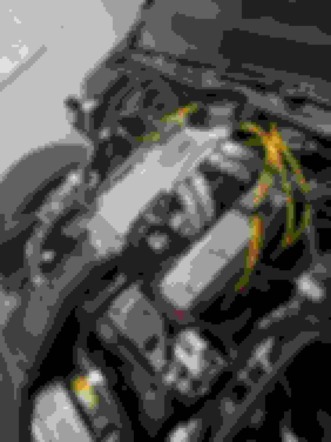
Here is a picture I took from the underside when I was doing the oil pan gasket that shows the oil pump distributor drive key to oil pump driveshaft engagement gap. How does it look?
Any suggestions are helpful, thanks!!
Last edited by yakmastermax; 10-12-2023 at 11:54 AM.
Hmmm... interesting.... so you're running coolant out of the back of the heads directly to the water neck.
I would imagine this helps by avoiding that pre-heated coolant from having to move through the cylinder head toward the front, picking up more heat and negatively affecting the cooling ability of the front cylinders? Thereby keeping the coolant temperature in the cylinder head more uniform from front to rear?
I haven't read through the entire thread, but was there some issue like detonation you were trying to resolve by doing this setup?
So there are a few reasons I decided to do my LT1 intake manifold conversion this way with the coolant being pulled from the rear. The first and main reason was that the position of the throttle body cable mechanism basically precluded pulling coolant from the driver front side of the manifold. Any fitting I would have put there would have resulted in interference between the hose and or fitting and the throttle cable mechanism.
On the front passenger side the issue was that a 90 degree fitting didn't have the clearance to be threaded in and tightened down. You can see I used a vertical fitting there. In order to route the coolant to the thermostat I wanted to use a 90 degree fitting.
So that left the two rear corners where there was room for the 90 degree fittings.
I did toy around with the reasoning that the stock L98 coolant flow route results in increased heat at cylinders 7 and 8 and at the rear of the block in general, but I decided that I didn't have enough information to validate that hypothesis and that even if that were true, by pulling coolant from the rear, it was unclear if I was helping or hurting. I hope that I basically was just breaking even, with no total improvement or degradation in the overall cooling performance, locally measured or considering temperature differentials from front to back.
I did this conversion not to address any prior known knock or detonation.
Last edited by yakmastermax; 10-12-2023 at 08:03 PM.
Here is a picture I took from the underside when I was doing the oil pan gasket that shows the oil pump distributor drive key to oil pump driveshaft engagement gap. How does it look?
That is the best way to properly fit the distributor for a new setup, with the oil pan removed so you van see proper engagement. It looks fine as far as the OP tang goes. There's a lot demanded of the camshaft to drive the distributor gear which drives the oil pump, and the camshat drive gear drives the distributor upward significantly so there should be minimal play, they make shim kits to set this up, driving out the pin and shimming.
 04-20-2023, 09:18 PM