


HID Beam Pattern Test
Thread Starter
Race Director


Joined: Jul 2008
Posts: 17,767
Likes: 3,695
From: The Sunshine State
2022 C5 of the Year Finalist - Modified
2021 C5 of the Year Finalist - Modified
C7 of the Year - Modified Finalist 2021
Finalist 2020 C7 of the Year -- Modified
2020 C5 of the Year Finalist - Modified
C5 of Year Finalist (appearance mods) 2019
2018 C5 of Year Finalist
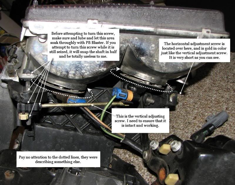
Can anyone recommend a good beam pattern test for HIDs? I just installed a set of ACA 4300 HIDs and I want to make sure I have them aimed correctly. I want to make any adjustments before I put the lids and shrouds back on the pop-ups. I know where the adjustment rods are and I made sure to lube them before putting the ACA housings back into the frames.

Team Owner


Joined: Dec 2003
Posts: 21,847
Likes: 140
From: When all is said and done... there is a hell of a lot more said than done. Riverside,Texas
St. Jude Donor '05 thru '26
Here's how you do it on a C6:
"That's the vertical adjustment (there is no horizontal adjustment). On a flat level surface, set the car exactly 25 feet from a wall. Mark a horizontal line on the wall the same height as the HID capsule. Turn on the lights and adjust the screw until the very top of the bright zone touches the line you just made."
"That's the vertical adjustment (there is no horizontal adjustment). On a flat level surface, set the car exactly 25 feet from a wall. Mark a horizontal line on the wall the same height as the HID capsule. Turn on the lights and adjust the screw until the very top of the bright zone touches the line you just made."
Le Mans Master

Joined: May 2006
Posts: 5,747
Likes: 224
From: Hillsboro Oregon
From earlier posts from CF
Originally Posted by RPOZ4Z
the "sweet spot" seems to be around 24 1/2" to 25" about 3 feet from the front bumper.
also depends if your car is lowered or not.
Originally Posted by jdmvette
i have also used an easy trick that is available since these bulbs have such a sharp cutoff.
i have taken my car around the block at night and checked to see if the lights shined into the cars that are parked on the street.
if i could see that they were shining into the windshield, i lowered them. now the cutoff does not go above the belt line of most cars that i passed and even then it's still below the window line.
it's not exactly scientific but it worked for me and i don't get any flashes.
Former Vendor
Joined: Nov 2005
Posts: 8,995
Likes: 2
From: Spring Texas
St. Jude Donor '08
Your ACA lights have a DOT Stepped pattern, the left side should be lower than the right side.
I like to aim from 25' or more on a level surface onto a white wall.
Vertical adjustment: the low side (left side) of your stepped cutoff should be between 22" and 24" from the ground. (If your car has been lowered, drop this to 20-22" depending on how much lower your car is)
Both left and right headlights should be aimed so the low steps line up.
Horizontal adjustment: The "step" is the center of the beam They should fire straight forward. To verify this, stand behind the outer tail light on either side with a plumbline or a straight stick. There should be a straight line between the outer tail light, projector and the center of the cutoff.
Should end up similar to this:
Tech Contributor

Joined: Dec 2003
Posts: 19,384
Likes: 87
From: Horncastle Lincolnshire, England
2023 C5 of the Year Finalist - Unmodified
I can't see why aiming HIDs should be any different from aiming other types of headlights. You need a pattern which puts most light in the area of interest without blinding oncoming drivers
Here's a How To I put together from the manual which should help. Just ignore the first part about the stock lights.
Aiming your Head Lights
Preparation:
Prepare the aiming area. You can use the garage wall providing its at least 25’ from the car and the ground is level.
Mark some calibration lines using chalk or masking tape:
Find the center of the headlight and measure the distance to the ground. Mark a horizontal line on the surface (garage door or wall) using masking tape at the same distance from the ground.
Stick a piece of tape in the center of the windscreen and another on the rear glass to use as reference marks.
Line these up from behind the car and use them to mark the centerline of the car on the wall.
Measure the distance between the center of both headlight lenses and use this to measure from the center point you just marked on the surface.
Make sure the tire pressures are correct and the tank is full or the calibration may be out. Park the vehicle square with the aiming surface. Close the doors and rock the car to stabilise the suspension.
Lubricate the adjusting screws and let them sit for a while
Adjustment
Horizontal and vertical aiming is done by moving the adjusting screws which moves the headlamp capsule in relation to the headlamp frame. The horizontal adjustment screw is located on the inboard side of each of the headlight assemblies and covered by a plug. The vertical adjustment screw is located on the inboard side of each of the headlight assemblies below the lower edge of the headlamp bezel. Its a long golden rod. I think it’s a #15 torx.
Raise the hood.
Raise the headlamps.
Remove the headlamp adjustment screw plug from the headlamp bezel. Reach under the headlamp bezel and push out the plug from behind.
Turn ON the low beam lamps. Block the light from the passenger lamp to allow you to adjust the drivers lamp. Don’t cover the headlight or it may get too hot.
Inspect the horizontal aim. Make the adjustments with reference to the lines and numbers on the aiming chart below
Adjust the aim using the horizontal adjusting screw, to align the break point (3) of the high intensity zone to the headlamp vertical centerline (1), within the range of 38 mm (1.5 in) to the left (5) of the lamp vertical centerline (1), to 38 mm (1.5 in) to the right (4) of the lamp vertical centerline (1) on the aiming screen.
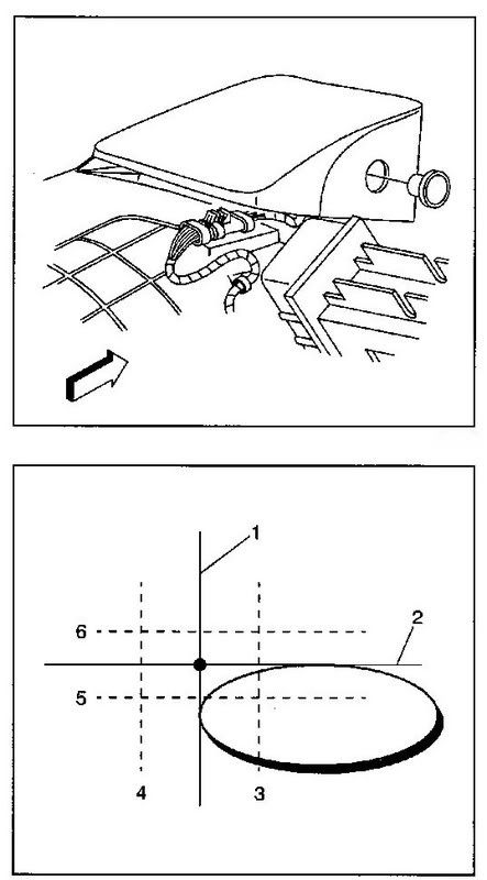
Inspect the vertical aim.
Adjust the aim using the vertical adjusting screw, to align the upper edge of the beam horizontal cut off line 114 mm (4.5 in) below (7) the headlamp horizontal centerline (2), within the range of 76 mm (3 in) below (8) the lamp horizontal centerline (2), to 191 mm (7.5 in) below (6) the lamp horizontal centerline (2) on the aiming screen.
Install the headlamp adjustment screw plug. Push to secure.
Turn OFF the headlamps.
Lower the hood.
Your light pattern should look roughly like this when you’re done.
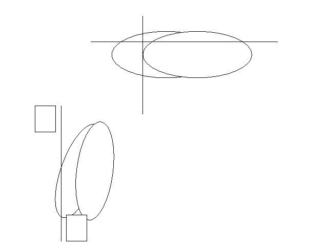
Thanks to Junkman for his pics
Here's a How To I put together from the manual which should help. Just ignore the first part about the stock lights.
Aiming your Head Lights
Preparation:
Prepare the aiming area. You can use the garage wall providing its at least 25’ from the car and the ground is level.
Mark some calibration lines using chalk or masking tape:
Find the center of the headlight and measure the distance to the ground. Mark a horizontal line on the surface (garage door or wall) using masking tape at the same distance from the ground.
Stick a piece of tape in the center of the windscreen and another on the rear glass to use as reference marks.
Line these up from behind the car and use them to mark the centerline of the car on the wall.
Measure the distance between the center of both headlight lenses and use this to measure from the center point you just marked on the surface.
Make sure the tire pressures are correct and the tank is full or the calibration may be out. Park the vehicle square with the aiming surface. Close the doors and rock the car to stabilise the suspension.
Lubricate the adjusting screws and let them sit for a while
Adjustment
Horizontal and vertical aiming is done by moving the adjusting screws which moves the headlamp capsule in relation to the headlamp frame. The horizontal adjustment screw is located on the inboard side of each of the headlight assemblies and covered by a plug. The vertical adjustment screw is located on the inboard side of each of the headlight assemblies below the lower edge of the headlamp bezel. Its a long golden rod. I think it’s a #15 torx.
Raise the hood.
Raise the headlamps.
Remove the headlamp adjustment screw plug from the headlamp bezel. Reach under the headlamp bezel and push out the plug from behind.
Turn ON the low beam lamps. Block the light from the passenger lamp to allow you to adjust the drivers lamp. Don’t cover the headlight or it may get too hot.
Inspect the horizontal aim. Make the adjustments with reference to the lines and numbers on the aiming chart below
Adjust the aim using the horizontal adjusting screw, to align the break point (3) of the high intensity zone to the headlamp vertical centerline (1), within the range of 38 mm (1.5 in) to the left (5) of the lamp vertical centerline (1), to 38 mm (1.5 in) to the right (4) of the lamp vertical centerline (1) on the aiming screen.
Inspect the vertical aim.
Adjust the aim using the vertical adjusting screw, to align the upper edge of the beam horizontal cut off line 114 mm (4.5 in) below (7) the headlamp horizontal centerline (2), within the range of 76 mm (3 in) below (8) the lamp horizontal centerline (2), to 191 mm (7.5 in) below (6) the lamp horizontal centerline (2) on the aiming screen.
Install the headlamp adjustment screw plug. Push to secure.
Turn OFF the headlamps.
Lower the hood.
Your light pattern should look roughly like this when you’re done.
Thanks to Junkman for his pics
Corvette Stories
The Best of Corvette for Corvette Enthusiasts

Top 10 Most Expensive Corvettes Ever Sold on Bring A Trailer
Brett Foote
10 Things Every Corvette Owner Needs (2026 Edition)
Michael S. Palmer
8 Most "Only Corvette Owners Understand" Quirks and Problems
Pouria Savadkouei
10 Reasons the C6 Z06 is Still A Performance Benchmark After 20 Years
Joe Kucinski
How Much Horsepower Every Corvette Engine "LOST" in 1972
Joe Kucinski
Top 10 DOs and DON'Ts for Protecting Your Convertible Top!
Michael S. Palmer
Top 10 Most Explosive Corvettes Ever Made: Power-to-Weight Ratio Ranked!
Joe Kucinski
150 hp to 1,250 hp: Every Corvette Generation Compared by the Specs That Matter
Joe Kucinski
8 Coolest Corvette Pace Cars (and Replicas) of All Time
Verdad GallardoFormer Vendor
Joined: Nov 2005
Posts: 8,995
Likes: 2
From: Spring Texas
St. Jude Donor '08
The idea behind the cutoff is that you can aim your beam higher and with more precision without blinding other drivers.
HIDs in a reflector (like the plug and play kits) have this pattern:

These you would aim using the traditional OEM aiming chart.
HIDs in a projector (like the light cannons) have this pattern:


Former Vendor
Joined: Nov 2005
Posts: 8,995
Likes: 2
From: Spring Texas
St. Jude Donor '08
That is the Ideal cutoff pattern probably from a 3" TSX or FX projector with clear lens and color-modified spacing. The Hella 90mm projectors in the Light cannons have a smaller fresnel lens that doesn't produce as sharp of a pattern.
This is my personal setup: E55 Bi-X projectors with ZKW lens, modified shield and color spacing.

I cut the shield to drop down a little lower on the passenger side. This is just my personal preference
This is my personal setup: E55 Bi-X projectors with ZKW lens, modified shield and color spacing.
I cut the shield to drop down a little lower on the passenger side. This is just my personal preference
Tech Contributor
Joined: Dec 2003
Posts: 19,384
Likes: 87
From: Horncastle Lincolnshire, England
2023 C5 of the Year Finalist - Unmodified

I noticed a big difference between my Euros and the stock US lights. As with the HIDs the Euros have much better beam shaping.
Former Vendor
Joined: Nov 2005
Posts: 8,995
Likes: 2
From: Spring Texas
St. Jude Donor '08

Note, the T84s are NOT HID friendly. The pattern gets all gross-like

Instructor


Joined: Nov 2009
Posts: 228
Likes: 9
From: Pittsburgh, PA
There were HIDs in the Z I recently picked up, and I know for a fact the lights are too high because I can see them shining in oncoming traffic's faces. So I want to aim them down, and I understand how to aim them, but how is everyone getting such sharp cut-offs with their HIDs in stock head lamps? My beams are ALL over the place. I am guessing people install projectors in their stock flip-ups? Who makes a kit with projectors, I would be very interested in picking a set up in the future.
Former Vendor
Joined: Nov 2005
Posts: 8,995
Likes: 2
From: Spring Texas
St. Jude Donor '08
There were HIDs in the Z I recently picked up, and I know for a fact the lights are too high because I can see them shining in oncoming traffic's faces. So I want to aim them down, and I understand how to aim them, but how is everyone getting such sharp cut-offs with their HIDs in stock head lamps? My beams are ALL over the place. I am guessing people install projectors in their stock flip-ups? Who makes a kit with projectors, I would be very interested in picking a set up in the future.
I offer two kits Fixed and pop up:


Thread Starter
Race Director
Joined: Jul 2008
Posts: 17,767
Likes: 3,695
From: The Sunshine State
2022 C5 of the Year Finalist - Modified
2021 C5 of the Year Finalist - Modified
C7 of the Year - Modified Finalist 2021
Finalist 2020 C7 of the Year -- Modified
2020 C5 of the Year Finalist - Modified
C5 of Year Finalist (appearance mods) 2019
2018 C5 of Year Finalist
Former Vendor
Joined: Nov 2005
Posts: 8,995
Likes: 2
From: Spring Texas
St. Jude Donor '08
Tech Contributor
Joined: Aug 1999
Posts: 16,376
Likes: 404
From: Should this thoughtful, valuable contribution meet with no acknowledgement or 'thanks' this post----
In a perfect world (perfectly flat for that matter) this is all great. When I did mine I loved the increased light. However, in reality HIDs will get you noticed more than you want. The problem is in hilly terrain. No matter how they are set if you are coming over a hill an oncoming driver will get blinded at some point. Newer cars now have adaptive HIDs that adjust to various conditions...this is what should be the next lighting mod for vettes....allowing both high and low beams on is a step in the wrong direction too.
Melting Slicks

Joined: Nov 2008
Posts: 2,938
Likes: 65
From: Rochester Hills MI
lights dont need hid's to have a cutoff, they just need to have projector lenses. i have halogen ACA projectors, and i still have a cutoff that looks exactly the same as hid setups.