
Brake Swap tools help

Thread Starter
Supporting Vendor


Joined: Jul 2010
Posts: 8,550
Likes: 901
From: Republic of Texas
I'm going to a friend's place to do a brake swap (calipers, stainless lines, pads and rotors....all factory size)
I need to make sure I have All the tools i will need since I'm doing this out of my shop.
Can anyone provide me the required tools list?
thanks,
George
I need to make sure I have All the tools i will need since I'm doing this out of my shop.
Can anyone provide me the required tools list?
thanks,
George
Tech Contributor


Joined: Dec 2003
Posts: 19,384
Likes: 87
From: Horncastle Lincolnshire, England
2023 C5 of the Year Finalist - Unmodified
Brake Rotor and Brake Pad Replacement
This �How To� has been written using the GM manual as a source and including pictures from my own pad and rotor change. Brakes are safety critical so use it at your own risk. If you are not happy working on the braking system give the job to a professional.
Tools Required:
Ratchet with 15mm socket (for caliper bolts)
18mm wrench for caliper bolt collar (front)
16mm wrench for caliper bolt collar (rear)
Or use an adjustable wrench
13/16� socket for caliper mounting bracket bolts.
Breaker bar or torque wrench
Hammer
Screwdriver
Low profile jack
Blow torch
Loctite
Degreaser
Wire to support calipers (a short bungee cord could also be used)
Front
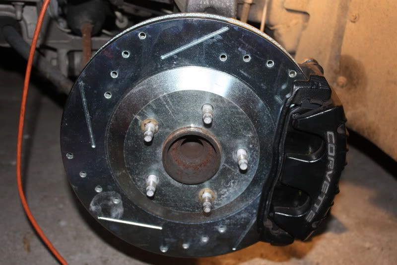
Identify the front and rear rotors and direction of rotation. The front rotors have a bevelled edge on the hub ring. The rear rotors have a vertical edge
The slots are closer to the hub at the front and wider at the back in the direction of rotation. This disseminates the heat outwards from the rotors. My rear rotors were marked with RR/RL but there were no markings on the front rotors.
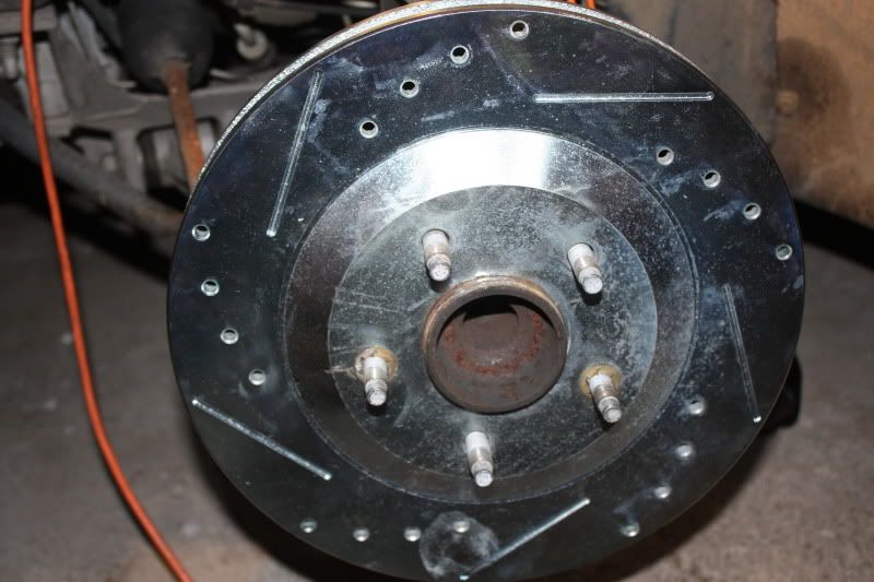
Front Rotor
Rear Rotor
Removal
Raise and support the vehicle.
When you are jacking the vehicle at the front, make sure that the jack or the jack lift pad does not make contact with the front fascia, the air dam or the fenders or you could cause damage. Avoid contact with the engine oil pan (2) and the front suspension leaf spring. Place a block or pad between the jack lift pad and the jacking point and make sure it spans at least 2 suspension cross member ribs (1). I then turned the wheels to give better access to the bolts.

Diagram 1.
Once you�ve raised the car, put in a jack stand for safety.
Remove the road wheel.
Remove the brake fluid reservoir cap and make sure the level is about half way between min and max. If not drain a little fluid or you risk an overflow when you compress the calipers later in the procedure.
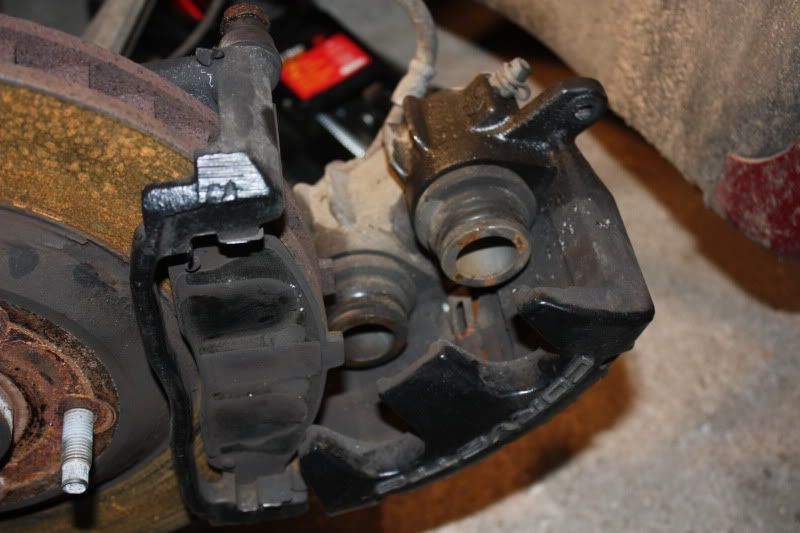
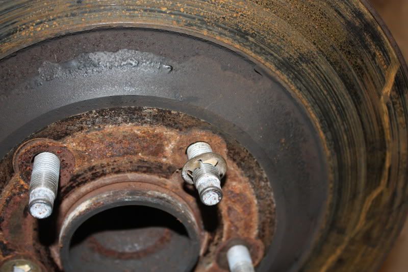
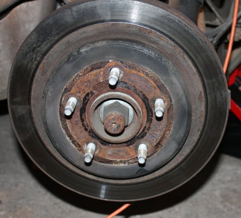
This is probably what you�ll see. My car has been washed a few times without being driven so the old rotors had a slight film of rust.
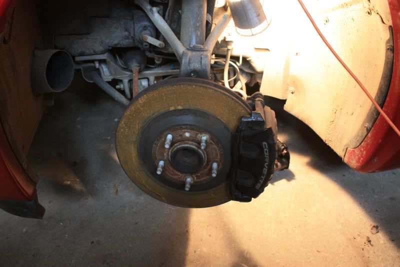
When you remove the bolts on the calipers and mountings remember the �righty tighty, lefty loosy rule. Look at the bolt you are removing and make sure you turn the wrench the correct way. Remember the bolts are facing towards you so it may not be intuitive. The bolts will have been fitted using loctite and torque tight so they will probably take significant effort to break them loose, particularly the larger caliper mounting bracket bolts (torqued to 125 Lb/ft)!
Warning: Make sure the car is securely supported on the jacks as you�ll exert a lot of pressure on the bolts. Be careful not to lean heavily against the bodywork or you may damage the fender. You may need a large breaker bar or apply some heat from a blow torch to loosen the bolts.
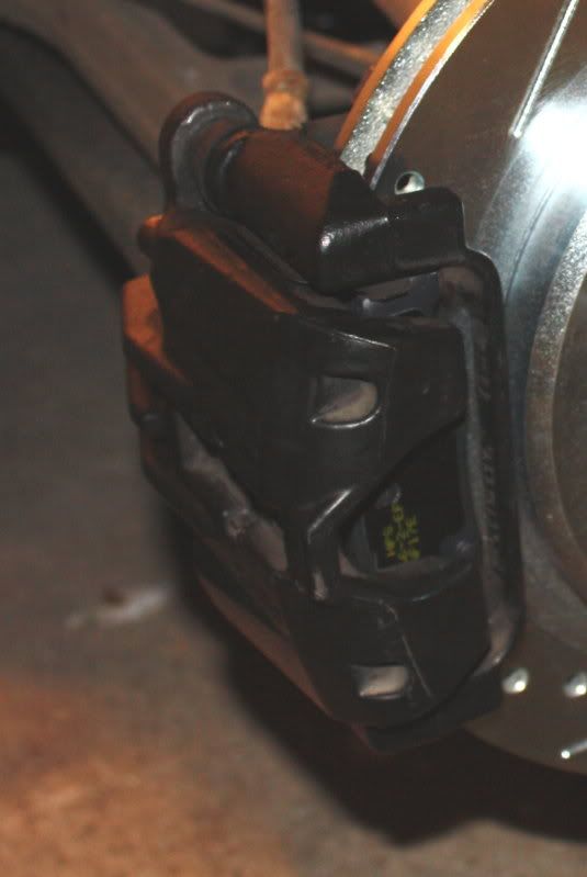
The caliper bolt fits through the bracket on the caliper into a rotating threaded collar with a rubber boot which is mounted on the caliper bracket (see picture below).
Loosen the two bolts (top and bottom) holding the brake caliper to the caliper mounting bracket.
Remove the top caliper bolt. To do this you need to turn the 15mm bolt while preventing the collar behind the bracket from rotating using the 18mm wrench.
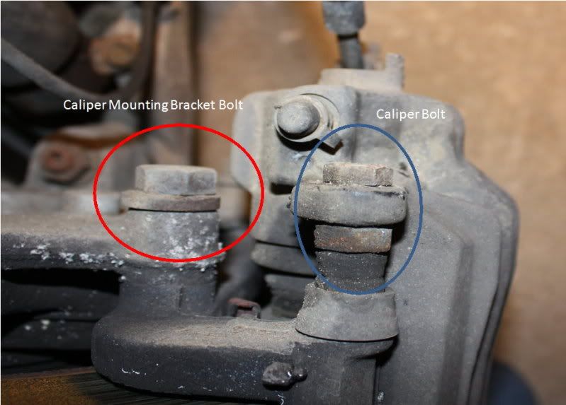
(Caliper assembly viewed from above showing bolts)
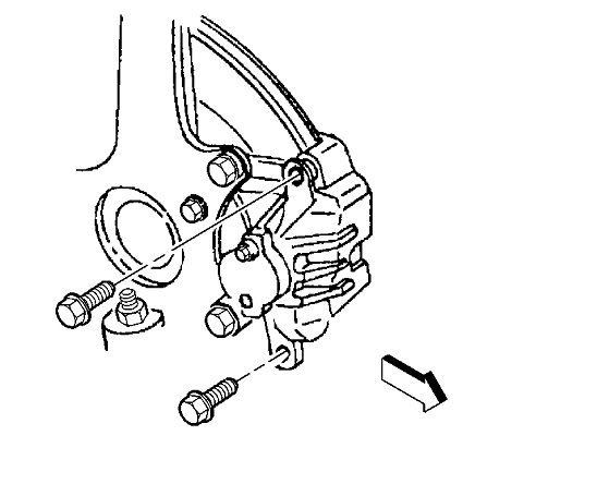
Diagram 2. Caliper bolts.
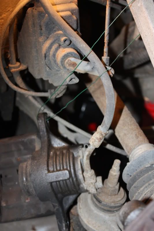
Rotate the caliper clockwise and support the caliper assembly with wire (I threaded the wire through the top mounting hole and passed it around the leaf spring) ensuring that there�s no tension on the hydraulic brake flexible hose. Do not disconnect the hydraulic brake flexible hose or you�ll need to bleed the system later.
Remove the bottom caliper bolt and move the caliper assembly aside keeping the tension off the brake line.
Remove the old brake pads. There�s a small tab on the pad. The book says: �The brake pad wear sensor, mounted on the inboard brake pad, must be positioned so that it is in the trailing position during forward rotation of the brake rotor�. I read that as the top of the inboard pad (point of last contact). The picture from the manual shows it at the bottom of the outside pad. My old pads had it positioned at the top edge of the inside pad at the front so, hopefully, GM got it right during build! If the wear sensor is fitted incorrectly its possible you will get noise or even rapid pad wear, binding and overheating of the brakes.
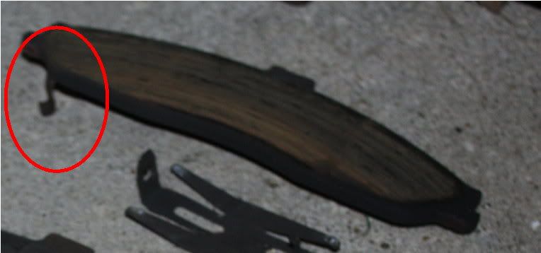
(Clip extending from back of pad)
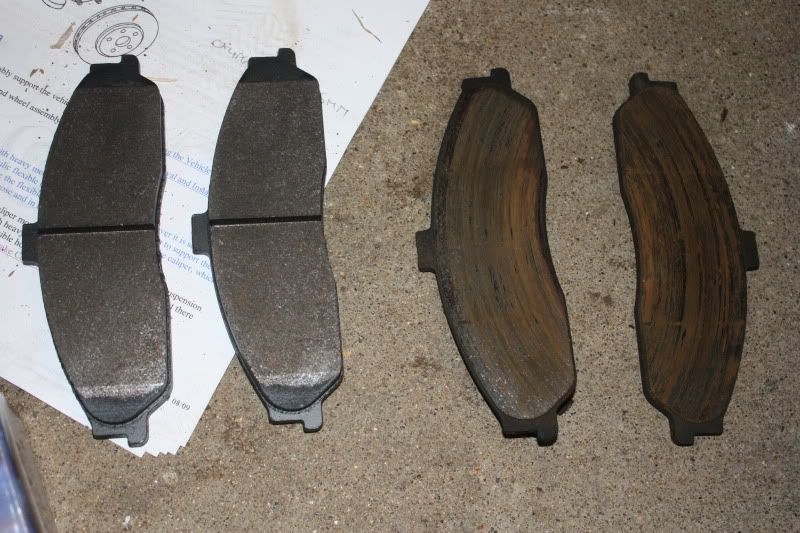
Here�s a comparison between the new and the old (very well worn) OEM pads.
Remove the two larger bolts (upper and lower) from the caliper mounting bracket using a 13/16� socket and a long handled wrench. Lift the bracket clear. These bolts are very tight and it will take a considerable effort to break them loose.
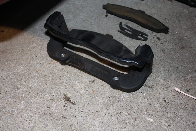
Caliper Mounting Bracket
There are two springs fitted top and bottom of the caliper mounting bracket. Make sure these remain in place. There�s a further spring which you can see in the picture above that fits inside the caliper. It shouldn�t come out but if you remove it make sure you refit it the correct way round as it holds the brake pads in place when reassembled.
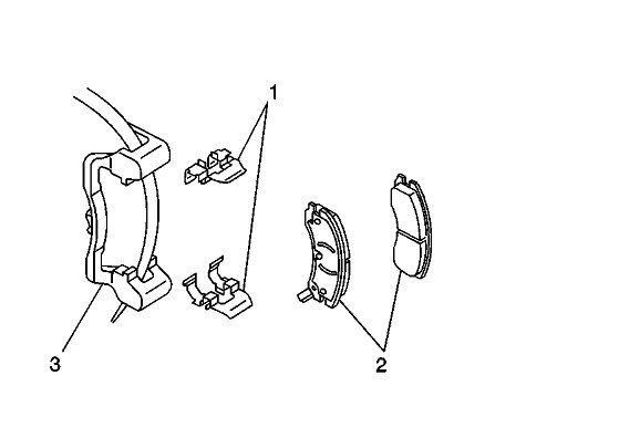
Diagram 3. Caliper Mounting Bracket, retaining springs and pads.
Remove the spring washers which hold the rotor in place. You can refit these if you wish but they are not actually needed. The rotors hold in place with the pressure from the wheel lock nuts. They were fitted to hold the rotors in place on the production line.
Remove the brake rotor which should lift off easily.
Clean up the various parts particularly, removing rust or contaminants from the wheel bearing flange and the brake rotor mating surfaces. If you don�t, you risk lateral movement of the brake rotor and brake pulsing.
Reassembly
Use Loctite or similar thread locking fluid on the bolts when you reassemble the calipers. Additionally, GM recommend using new caliper bolts.
Install the new brake rotor over the wheel studs onto the wheel bearing flange.
Refit the brake caliper mounting bracket using some loctite on the nuts. Tighten the front brake caliper mounting bracket bolts to 125 lb ft (175 N�m). Make sure the clips are still in place.
Reinstall the lower bolt into the brake caliper assembly using some loctite on the thread.
Fit the new brake pads. They slot in from either side into the upper and lower guides.
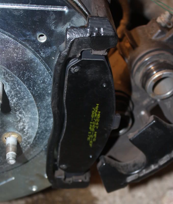
Another reminder; make sure you put the correct pads in the correct location. The old pads had witness marks from the calipers with two circular marks on the inner pad where the pistons had been pressing. If you mix up the two pads this will allow you to identify the correct one and get the clip located correctly.
Use a large C-clamp to compress the brake pistons. Fit the clamp (1) over the body of the brake caliper (3) with the C-clamp ends against the rear of the caliper body and against an old inboard brake pad (2) or a wood block positioned against the caliper pistons. Make sure you don�t make contact with the brake hose or fittings or you may damage them. Gently turn the C clamp to compress the pistons. Take it slowly or you�ll cause an overflow at the cylinder. You�ll need to compress them almost fully to get the caliper back on as the new pads are much thicker than the ones that you removed.

Diagram 4. C Clamp used to compress pistons.
Support the caliper, remove the supporting wire and position the caliper against the mounting bracket. Fit the lower bolt.
Rotate the brake cylinder counter-clockwise easing the pistons over the new pads (this picture shows the old pads but you get the idea).
Fit the upper caliper bolt. Tighten the brake caliper guide pin bolt to 23 lb ft (31 N�m).
If you want to repaint your calipers, now would be a good time.
With the engine off, gradually apply the brake pedal to approximately 2/3 of its travel. Slowly release the brake pedal. Wait 15 seconds, then repeat until the brake pedal is firm.
Check the calipers and mountings for security.
Refit the road wheel.
Lower the vehicle.
Rear Pads and Rotors
Make sure the E Brake is off.
When you are jacking the vehicle at the rear, make sure that the jack or the jack lift pad does not make contact with the rear suspension mono leaf spring or you could cause damage. Place a block or pad between the jack lift pad and the jacking point and make sure it spans at least 2 suspension cross member ribs.
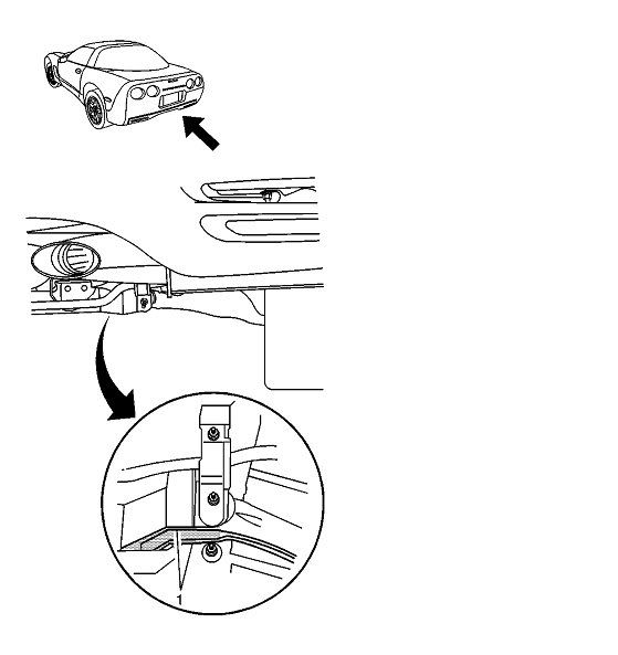
Diagram 5 Rear Jacking Point
Once you�ve raised the car, put in a jack stand for safety.
Remove the road wheel.
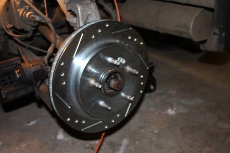
You�ll notice that the rear discs are different to the front having a right angled bevel.
Rear Rotor
The rear caliper is smaller than the front caliper and is fitted with a single piston
You�ll see that the brake line runs across the area behind the caliper mounting bracket bolts. The caliper will have to be removed before you can get in at the larger bolts or you risk damaging the brake lines.
Loosen the two bolts (top and bottom) holding the brake caliper to the caliper mounting bracket.
Remove the top caliper bolt.
Rotate the caliper clockwise and support the caliper assembly with wire ensuring that there�s no tension on the hydraulic brake flexible hose. Do not disconnect the hydraulic brake flexible hose.
Remove the lower bolt and move the caliper clear.
Follow the same procedure as the front to remove the caliper mounting brackets.
Remove the two clips holding the rotor in place and remove the rotor. Because of the E Brake you may find you need a few taps with a hammer to break it free.
You�ll find a lot of road debris and grease around the E Brake adjusters. Clean this up before reassembly. Parking brake adjustment is not necessary as the parking brake cables can be tensioned automatically by cycling the parking brake lever three times. If you feel the need, you can adjust the parking brake shoe-to-drum clearance by rotating the adjustment nut on the park brake actuator. The specification value is 0.38 mm (0.015 in). GM has a special tool to make this measurement.
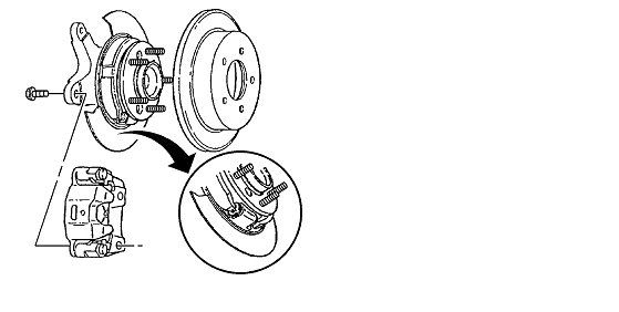
Diagram 6. Refit the new rotor.
Reassembly is the same as the front. The brake pad wear clips are also fitted at the trailing edge of the caliper (point of last contact) but as the unit is on the opposite side of the rotor that�s the bottom as you look at it. Initially, that seemed counter-intuitive to me! In any event, I reassembled it as it had been assembled at the factory.
With the engine off, gradually apply the brake pedal to approximately 2/3 of its travel. Slowly release the brake pedal. Wait 15 seconds, then repeat until the brake pedal is firm.
Replace the brake fluid reservoir cap.
Refit the road wheel.
Lower the vehicle.
Bedding-In the Brakes
It�s important to burnish the new pads and mate them to the new rotors.
As you drive off for the first time, make sure you have brake pressure and that there�s no vibration or binding under braking.
Select a long straight stretch of clear road.
Accelerate to 30 mph. Using moderate to firm pressure, apply the brakes to bring the vehicle to a stop. Do not allow the brakes to lock or overheat.
Repeat this 20 times.
As you�ve replaced the rotors and pads it might be timely to flush and replace the brake fluid once you�ve confirmed there are no problems.
All diagrams � Copyright General Motors Corporation.
Thanks for inputs: Vega$Vette, Z06ster
This �How To� has been written using the GM manual as a source and including pictures from my own pad and rotor change. Brakes are safety critical so use it at your own risk. If you are not happy working on the braking system give the job to a professional.
Tools Required:
Ratchet with 15mm socket (for caliper bolts)
18mm wrench for caliper bolt collar (front)
16mm wrench for caliper bolt collar (rear)
Or use an adjustable wrench
13/16� socket for caliper mounting bracket bolts.
Breaker bar or torque wrench
Hammer
Screwdriver
Low profile jack
Blow torch
Loctite
Degreaser
Wire to support calipers (a short bungee cord could also be used)
Front
Identify the front and rear rotors and direction of rotation. The front rotors have a bevelled edge on the hub ring. The rear rotors have a vertical edge
The slots are closer to the hub at the front and wider at the back in the direction of rotation. This disseminates the heat outwards from the rotors. My rear rotors were marked with RR/RL but there were no markings on the front rotors.
Front Rotor
Rear Rotor
Removal
Raise and support the vehicle.
When you are jacking the vehicle at the front, make sure that the jack or the jack lift pad does not make contact with the front fascia, the air dam or the fenders or you could cause damage. Avoid contact with the engine oil pan (2) and the front suspension leaf spring. Place a block or pad between the jack lift pad and the jacking point and make sure it spans at least 2 suspension cross member ribs (1). I then turned the wheels to give better access to the bolts.
Diagram 1.
Once you�ve raised the car, put in a jack stand for safety.
Remove the road wheel.
Remove the brake fluid reservoir cap and make sure the level is about half way between min and max. If not drain a little fluid or you risk an overflow when you compress the calipers later in the procedure.
This is probably what you�ll see. My car has been washed a few times without being driven so the old rotors had a slight film of rust.
When you remove the bolts on the calipers and mountings remember the �righty tighty, lefty loosy rule. Look at the bolt you are removing and make sure you turn the wrench the correct way. Remember the bolts are facing towards you so it may not be intuitive. The bolts will have been fitted using loctite and torque tight so they will probably take significant effort to break them loose, particularly the larger caliper mounting bracket bolts (torqued to 125 Lb/ft)!
Warning: Make sure the car is securely supported on the jacks as you�ll exert a lot of pressure on the bolts. Be careful not to lean heavily against the bodywork or you may damage the fender. You may need a large breaker bar or apply some heat from a blow torch to loosen the bolts.
The caliper bolt fits through the bracket on the caliper into a rotating threaded collar with a rubber boot which is mounted on the caliper bracket (see picture below).
Loosen the two bolts (top and bottom) holding the brake caliper to the caliper mounting bracket.
Remove the top caliper bolt. To do this you need to turn the 15mm bolt while preventing the collar behind the bracket from rotating using the 18mm wrench.
(Caliper assembly viewed from above showing bolts)
Diagram 2. Caliper bolts.
Rotate the caliper clockwise and support the caliper assembly with wire (I threaded the wire through the top mounting hole and passed it around the leaf spring) ensuring that there�s no tension on the hydraulic brake flexible hose. Do not disconnect the hydraulic brake flexible hose or you�ll need to bleed the system later.
Remove the bottom caliper bolt and move the caliper assembly aside keeping the tension off the brake line.
Remove the old brake pads. There�s a small tab on the pad. The book says: �The brake pad wear sensor, mounted on the inboard brake pad, must be positioned so that it is in the trailing position during forward rotation of the brake rotor�. I read that as the top of the inboard pad (point of last contact). The picture from the manual shows it at the bottom of the outside pad. My old pads had it positioned at the top edge of the inside pad at the front so, hopefully, GM got it right during build! If the wear sensor is fitted incorrectly its possible you will get noise or even rapid pad wear, binding and overheating of the brakes.
(Clip extending from back of pad)
Here�s a comparison between the new and the old (very well worn) OEM pads.
Remove the two larger bolts (upper and lower) from the caliper mounting bracket using a 13/16� socket and a long handled wrench. Lift the bracket clear. These bolts are very tight and it will take a considerable effort to break them loose.
Caliper Mounting Bracket
There are two springs fitted top and bottom of the caliper mounting bracket. Make sure these remain in place. There�s a further spring which you can see in the picture above that fits inside the caliper. It shouldn�t come out but if you remove it make sure you refit it the correct way round as it holds the brake pads in place when reassembled.
Diagram 3. Caliper Mounting Bracket, retaining springs and pads.
Remove the spring washers which hold the rotor in place. You can refit these if you wish but they are not actually needed. The rotors hold in place with the pressure from the wheel lock nuts. They were fitted to hold the rotors in place on the production line.
Remove the brake rotor which should lift off easily.
Clean up the various parts particularly, removing rust or contaminants from the wheel bearing flange and the brake rotor mating surfaces. If you don�t, you risk lateral movement of the brake rotor and brake pulsing.
Reassembly
Use Loctite or similar thread locking fluid on the bolts when you reassemble the calipers. Additionally, GM recommend using new caliper bolts.
Install the new brake rotor over the wheel studs onto the wheel bearing flange.
Refit the brake caliper mounting bracket using some loctite on the nuts. Tighten the front brake caliper mounting bracket bolts to 125 lb ft (175 N�m). Make sure the clips are still in place.
Reinstall the lower bolt into the brake caliper assembly using some loctite on the thread.
Fit the new brake pads. They slot in from either side into the upper and lower guides.
Another reminder; make sure you put the correct pads in the correct location. The old pads had witness marks from the calipers with two circular marks on the inner pad where the pistons had been pressing. If you mix up the two pads this will allow you to identify the correct one and get the clip located correctly.
Use a large C-clamp to compress the brake pistons. Fit the clamp (1) over the body of the brake caliper (3) with the C-clamp ends against the rear of the caliper body and against an old inboard brake pad (2) or a wood block positioned against the caliper pistons. Make sure you don�t make contact with the brake hose or fittings or you may damage them. Gently turn the C clamp to compress the pistons. Take it slowly or you�ll cause an overflow at the cylinder. You�ll need to compress them almost fully to get the caliper back on as the new pads are much thicker than the ones that you removed.
Diagram 4. C Clamp used to compress pistons.
Support the caliper, remove the supporting wire and position the caliper against the mounting bracket. Fit the lower bolt.
Rotate the brake cylinder counter-clockwise easing the pistons over the new pads (this picture shows the old pads but you get the idea).
Fit the upper caliper bolt. Tighten the brake caliper guide pin bolt to 23 lb ft (31 N�m).
If you want to repaint your calipers, now would be a good time.
With the engine off, gradually apply the brake pedal to approximately 2/3 of its travel. Slowly release the brake pedal. Wait 15 seconds, then repeat until the brake pedal is firm.
Check the calipers and mountings for security.
Refit the road wheel.
Lower the vehicle.
Rear Pads and Rotors
Make sure the E Brake is off.
When you are jacking the vehicle at the rear, make sure that the jack or the jack lift pad does not make contact with the rear suspension mono leaf spring or you could cause damage. Place a block or pad between the jack lift pad and the jacking point and make sure it spans at least 2 suspension cross member ribs.
Diagram 5 Rear Jacking Point
Once you�ve raised the car, put in a jack stand for safety.
Remove the road wheel.
You�ll notice that the rear discs are different to the front having a right angled bevel.
Rear Rotor
The rear caliper is smaller than the front caliper and is fitted with a single piston
You�ll see that the brake line runs across the area behind the caliper mounting bracket bolts. The caliper will have to be removed before you can get in at the larger bolts or you risk damaging the brake lines.
Loosen the two bolts (top and bottom) holding the brake caliper to the caliper mounting bracket.
Remove the top caliper bolt.
Rotate the caliper clockwise and support the caliper assembly with wire ensuring that there�s no tension on the hydraulic brake flexible hose. Do not disconnect the hydraulic brake flexible hose.
Remove the lower bolt and move the caliper clear.
Follow the same procedure as the front to remove the caliper mounting brackets.
Remove the two clips holding the rotor in place and remove the rotor. Because of the E Brake you may find you need a few taps with a hammer to break it free.
You�ll find a lot of road debris and grease around the E Brake adjusters. Clean this up before reassembly. Parking brake adjustment is not necessary as the parking brake cables can be tensioned automatically by cycling the parking brake lever three times. If you feel the need, you can adjust the parking brake shoe-to-drum clearance by rotating the adjustment nut on the park brake actuator. The specification value is 0.38 mm (0.015 in). GM has a special tool to make this measurement.
Diagram 6. Refit the new rotor.
Reassembly is the same as the front. The brake pad wear clips are also fitted at the trailing edge of the caliper (point of last contact) but as the unit is on the opposite side of the rotor that�s the bottom as you look at it. Initially, that seemed counter-intuitive to me! In any event, I reassembled it as it had been assembled at the factory.
With the engine off, gradually apply the brake pedal to approximately 2/3 of its travel. Slowly release the brake pedal. Wait 15 seconds, then repeat until the brake pedal is firm.
Replace the brake fluid reservoir cap.
Refit the road wheel.
Lower the vehicle.
Bedding-In the Brakes
It�s important to burnish the new pads and mate them to the new rotors.
As you drive off for the first time, make sure you have brake pressure and that there�s no vibration or binding under braking.
Select a long straight stretch of clear road.
Accelerate to 30 mph. Using moderate to firm pressure, apply the brakes to bring the vehicle to a stop. Do not allow the brakes to lock or overheat.
Repeat this 20 times.
As you�ve replaced the rotors and pads it might be timely to flush and replace the brake fluid once you�ve confirmed there are no problems.
All diagrams � Copyright General Motors Corporation.
Thanks for inputs: Vega$Vette, Z06ster

Banned Scam/Spammer
Joined: Feb 2007
Posts: 50,093
Likes: 267
From: Oklahoma City
St. Jude Donor '09-'10-'11-'12-'13-'14-'15-'16-'17,'19,'22


