When you click on links to various merchants on this site and make a purchase, this can result in this site earning a commission. Affiliate programs and affiliations include, but are not limited to, the eBay Partner Network.
As the days and years go flying by, we have new forum members that are having more and more issues with the electrical system. Some of our electrical issues are very strange and complex.
Anytime that you have an electrical problem that involves a C5 Module (PCM, BCM, TAC, HVAC, LDCM, RDCM EBTCM ect, etc.. you should ALWAYS check the modules input power & grounds. Most of those modules have TWO power inputs. HOT at all times" & HOT in RUN/START.
The HOT in RUN/START voltage comes from the ignition switch. If that voltage out of the ignition switch is compromised due to dirty/burnt contacts, you have TWO options. Order a new switch OR attempt to service your switch.
NOTE! Attempting to service your own switch isn't for the everyone. There are several procedures that SHOULD be conducted before you service the switch and after its serviced. Use an OHM METER and read the contact resistance BEFORE you take it apart. Record those resistances. When you are finished servicing the switch, READ THE CONTACT RESISTANCE before you reinstall it back in to the system! If it is not ZERO Ohms, something is wrong and you need to go back and correct that issue!
SERVICING THE SWITCH, Ive detailed that procedure at the beginning of the thread, HOWEVER, some people either don't understand what I wrote, don't have the skills to do it correctly or don't fully test the cleaned switch to verify that it was done correctly.
I mentioned re-bending the contact arms to allow them to close with more contact pressure. When you do that, you MUST insure that the contacts close and they close FLAT with the fixed contact. That involves sanding between the contacts to reform the faces.
Once the contacts are reformed, you must polish them and CLEAN them so that there is ZERO resistance (or as close to zero as you can get).
USE AN OHM METER to insure that the switch has zero resistance in each closed contact position.
Before you reinstall the ignition switch, take a very close look at the harness connectors that connect to the ignition switch! The female pins can and do spread apart. When this happens, you get poor contact and again, compromised voltage into the ignition switch. The correct method of testing those female contacts is to insert a male pin into the female pin to see if there good INSERTION & RETRACTION resistance (force) of the male pin. If its flops in and out, that pin is bad and need to be replaced or re-bent to make proper pin contact with the male pin.
Checking the ignition switch output voltage to a module is easy. The HOT in RUN/START bus goes to a module fuse. On top of each fuse are TWO small test points. Read each of those test points to chassis ground. You should see full battery voltage on BOTh of those contacts. If the voltage is less than battery voltage, the greater the difference the worse the contact or ignition switch voltage path is.
NOTE! The DC VOLT METER on the IPC and the digital voltage reading on the DIC "DOES NOT" indicate true battery voltage!!! It indicates voltage out of the ignition switch! If you have a low voltage on either of those indicators, compare them to the ACTUAL voltage directly on the battery terminals (engine off & engine ON)
Good luck my friends
Bill Curlee
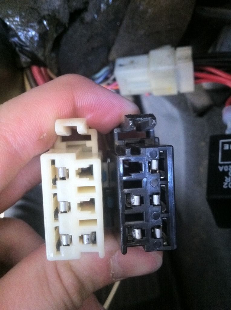
Ignition switch Harness Connector bent pins, Do the pin PUSH / PULL test to verify pins are good and tight on the male pins:
Another copy of the switch schematic:
Last edited by Bill Curlee; May 25, 2019 at 11:52 AM.
As the days and years go flying by, we have new forum members that are having more and more issues with the electrical system. Some of our electrical issues are very strange and complex.
Anytime that you have an electrical problem that involves a C5 Module (PCM, BCM, TAC, HVAC, LDCM, RDCM EBTCM ect, etc.. you should ALWAYS check the modules input power & grounds. Most of those modules have TWO power inputs. HOT at all times" & HOT in RUN/START.
The HOT in RUN/START voltage comes from the ignition switch. If that voltage out of the ignition switch is compromised due to dirty/burnt contacts, you have TWO options. Order a new switch OR attempt to service your switch.
NOTE! Attempting to service your own switch isn't for the everyone. There are several procedures that SHOULD be conducted before you service the switch and after its serviced. Use an OHM METER and read the contact resistance BEFORE you take it apart. Record those resistances. When you are finished servicing the switch, READ THE CONTACT RESISTANCE before you reinstall it back in to the system! If it is not ZERO Ohms, something is wrong and you need to go back and correct that issue!
SERVICING THE SWITCH, Ive detailed that procedure at the beginning of the thread, HOWEVER, some people either don't understand what I wrote, don't have the skills to do it correctly or don't fully test the cleaned switch to verify that it was done correctly.
I mentioned re-bending the contact arms to allow them to close with more contact pressure. When you do that, you MUST insure that the contacts close and they close FLAT with the fixed contact. That involves sanding between the contacts to reform the faces.
Once the contacts are reformed, you must polish them and CLEAN them so that there is ZERO resistance (or as close to zero as you can get).
USE AN OHM METER to insure that the switch has zero resistance in each closed contact position.
Before you reinstall the ignition switch, take a very close look at the harness connectors that connect to the ignition switch! The female pins can and do spread apart. When this happens, you get poor contact and again, compromised voltage into the ignition switch. The correct method of testing those female contacts is to insert a male pin into the female pin to see if there good INSERTION & RETRACTION resistance (force) of the male pin. If its flops in and out, that pin is bad and need to be replaced or re-bent to make proper pin contact with the male pin.
Checking the ignition switch output voltage to a module is easy. The HOT in RUN/START bus goes to a module fuse. On top of each fuse are TWO small test points. Read each of those test points to chassis ground. You should see full battery voltage on BOTh of those contacts. If the voltage is less than battery voltage, the greater the difference the worse the contact or ignition switch voltage path is.
NOTE! The DC VOLT METER on the IPC and the digital voltage reading on the DIC "DOES NOT" indicate true battery voltage!!! It indicates voltage out of the ignition switch! If you have a low voltage on either of those indicators, compare them to the ACTUAL voltage directly on the battery terminals (engine off & engine ON)
Good luck my friends
Bill Curlee
Ignition switch Harness Connector bent pins, Do the pin PUSH / PULL test to verify pins are good and tight on the male pins:
Another copy of the switch schematic:
If GM had coated all their Ignition switches and electrical contacts with IRIDIUM there would be no Corvette Forum...LOL !!!
So on my 2001 A4 I took the switch out and got it all sorted out but now I noticed my shift lock cable will not stay put / locked in into the key switch housing! The black tab seems fine but it pulls right out if I barely pull on it, so I am not sure whats going on here? Is there something that maybe fell out that holds the cable in the key switch?
Last edited by vettefx76; Jul 17, 2019 at 10:41 PM.
All well and good, but for my 99 auto coupe, I can't get the key to turn. So now I cannot move the car out of park, cannot remove the cable from the ignition and so far cannot remove the center console all the way. Right now I'm trying to remove a portion of the shifter boot to see if I can disconnect the cable from the shifter to remove the switch, cylinder and cable as an assembly. If so I can order a whole new switch/cylinder and take them to a locksmith with the old assembly. Hopefully he can drill out the cylinder, thereby releasing the cable to reinstall with the new switch/cylinder. Any way I can disconnect the shift cable from under the car to get the shifter into neutral so I can remove the console and to get to the cable?
Well, can't remove the boot all the way, because I can't get to the tabs to remove the indicator. So I still cannot remove the cable from either end. After looking at everything, I don't know what is preventing the shifter from moving. Whether the VATS terminal on the cylinder or the two relays on the ignition switch are connected or disconnected, the cable moves but the shifter won't move out of park. I've tried it both ways, Both sets of keys megger out the same (6 ohms) and operate everything else (doors, console glove box) but not the cylinder. "When I do insert either key, I get the "ding, ding, ding sound which I guess that means the VATS is good? This is frustrating to the extreme. There's gotta be a away around this. C'mon guys, this is 20 year old car, I can't believe I'm the first one to ever have this problem where on an automatic the key will not turn. What releases the frickin' cable from the ignition? Can I drill the cylinder out or what? Right now I'm not concerned with damaging the switch or cylinder, as I am prepared to replace them both. Help! As of now this is my daily driver and I have no other car avail. By the way, the locksmith will not drill it out while still in the car.
This may be an old thread but is still relevant today. Just wanted to give thanks for the thread. Fixed my weird electrical issues, fixed in a couple hours. Great schematic also.
I've removed my ignition switch, polished and cleaned the contacts (unfortunately didn't measure resistance because quite honestly I don't understand how to and/or what to put the multimeter leads on to measure), and now I'm ready to put it back into the car.
HOWEVER... the WHT/BLK and PRPL/WHT wires (from the key cylinder) are cut after the 2 pin connector. From the main wire harness, these wires are taped off. I'm wondering if this should be fixed, or if it's ok. I'm guessing it's from the aftermarket alarm system installed by a previous owner?
Big thanks from another victim of the damned ignition switch decay. Your well-written 2008 original post helped me go through the steps required for rejuvenating these bad contacts.
After looking closely into the switch, I realized that one of the reasons these contacts deteriorate early is that their geometry is not well controlled at manufacturing, considering the current they are supposed to carry. In my case the faces of some of the contacts were not machined flat, they were heavily chamfered on one of their edges.
The other issue I found – and this is my contribution to your thread – is that my contacts were not properly aligned, thus reducing the size of the contact patch and therefore the current capacity of the contact.
To visualize it, I used Prussian blue to spot the contact patch of each of the poles. The picture below shows the patch for the 3-pole assembly before adjustment. The contact on the right, which is the one which is always giving us trouble, is completely out of alignment and the area of the contact patch is very small. If I left it like this, I believe it would not be long before I would have problems again even after reworking the contact pads.
To correct the issue as best as possible, I VERY slightly bent the copper rail holding the contact arms with my fingers, in order to move the contact patches sideway and bring it back to the center of the square pad. Only apply a very soft touch to the bending of the copper rail, and proceed with one little step at the time.
The next picture shows the patches after tweaking the rail. The contact patches are now bigger and better centered on the contact pads, not perfect but better than before.
After wiping the Prussian blue and thoroughly cleaning the pads with alcohol, the switch is back together and the blinking gremlins are gone.
I am not sure the fix will survive another 20 years, but good enough as far as I am concerned.
I used a mechanical pencil with sand paper glued to the eraser to clean the fixed contacts. The eraser was trimmed down to fit the recess in the switch housing:
Once you apply more tension to the contacts, you will need to be careful when reinserting the arms back into the switch. The movable contact pads will tend to hang up on the fixed contacts. Assist them over the fixed contacts. I used a hooked paper clip to raise the arm over the fixed contact.
I used two flat blade screwdrivers to apply force to contacts A & B inside the switch contact well to keep the contact arms forced down on the fixed contacts to prevent them from popping out of place while installing the green cap. Once the contacts are in place,
snap the green cap back on the switch. Check the CLEANED contacts with an ohm meter. They should read very close to ZERO OHMS.
Please feel free to ask me any questions that you have. I feel I'm a IGNITION SWITCH expert now!
Marks old NASTY broken switch is as good as new!!!!!!!!!!
* NOTE!!!!! UP_DATED 10 Sep 2012:
Some DO's and DONT's
1. It is NOT necessary to disassemble the lower portion of the switch!! There is NOTHING in there electrical related!
2. Electrical contact cleaning: Deeply pitted contacts can be cleaned using 400 Wet & Dry paper but should be polished with finer & finer grits to a highly polished surface 400, 600, 800 1000 grit wet & dry paper and cleaned with alcohol when done polishing. If there not deeply pitted start with 800 grit. It is strongly recommended to assemble the switch contact arms and place sand paper between the contacts. Apply force on the movable contact arm and pull the sand paper THRU the contacts. This will seat the upper and lower contacts and put a larger contact patch on the contacts. The larger the contact patch on the switch contacts allow the contacts to pass higher currents before over heating!
3. Measure the repaired contacts with an OHM METER before reassembly!! If you dont have ZERO ohms, figure out why and fix it! Make sure that the OHM Meter is on the ohms X1 Scale or in auto mode and your really are reading ONE OHM or less. Cycle the switch several times and make sure you get constant good resistance readings!
4. When you insert the key into the switch lock tumbler, the end of the key pushes on the small button on the center of the tumbler well. Its important that you test the operation of that switch as it tells the BCM when the key is in or out of the switch/tumbler.
5. On the front of the tumbler is a small sensor. Inside that sensor are two small silver coated contacts. Those contacts read the resistor pellet embeded in your key. Measure the pellet in your key. insert the key into the sensor and measure the output of the sensor with the key in it. The two readings should match. If they dont the sensor contacts are dirty or damaged.
BC
Heres the procedure for removing the ignition switch from the dash:
Ignition Switch Replacement
Removal Procedure
Caution
Before servicing any electrical component, the ignition key must be in the OFF or LOCK position and all electrical loads must be OFF, unless instructed otherwise in these procedures. If a tool or equipment could easily come in contact with a live exposed electrical terminal, also disconnect the negative battery cable. Failure to follow these precautions may cause personal injury and/or damage to the vehicle or its components.
Disconnect the negative battery cable.
Apply the parking brake.
Remove the console. Refer to Compartment Replacement - Instrument Panel (I/P) .
+++++++++++++++++++++++++++++++++
Open the instrument panel (I/P) passenger compartment door.
Disconnect the electrical connector from the I/P compartment lamp switch.
Remove the trim plugs from the bottom of the compartment door. Reach behind the compartment door and push the plugs out. Use a suitable flat bladed tool on the front side to remove the plugs, if necessary.
Remove the lower retaining bolts from the I/P compartment.
Remove the side and upper retaining screws from the I/P compartment.
Slowly pull the I/P compartment just enough to disconnect the wiring harness connector from the inflatable restraint module switch.
Remove the I/P compartment.
Installation Procedure
Connect the wiring harness connector to the inflatable restraint I/P module switch connector.
Install the I/P compartment.
Loosely install the screw which retains the side of the I/P compartment, in order to align the nut on the passenger SIR bracket.
Notice
Use the correct fastener in the correct location. Replacement fasteners must be the correct part number for that application. Fasteners requiring replacement or fasteners requiring the use of thread locking compound or sealant are identified in the service procedure. Do not use paints, lubricants, or corrosion inhibitors on fasteners or fastener joint surfaces unless specified. These coatings affect fastener torque and joint clamping force and may damage the fastener. Use the correct tightening sequence and specifications when installing fasteners in order to avoid damage to parts and systems.
Install the upper retaining screw to the I/P compartment. Tighten
Tighten the retaining screw to 1.9 N�m (17 lb in).
Install the lower retaining bolts to the I/P compartment. Tighten
Tighten the retaining bolts to 12 N�m (106 lb in).
Align and hold the I/P compartment to the I/P, then install the side retaining screw to the I/P compartment. Tighten
Tighten the retaining screw to 1.9 N�m (17 lb in).
Install the trim plugs to the I/P compartment door.
Connect the electrical connector to the I/P compartment lamp switch.
Close the I/P passenger compartment door.
++++++++++++++++++++++++++++++++++
Remove the IP accessory trim plate. Refer to Trim Plate Replacement - Instrument Panel (I/P) Accessory .
++++++++++++++++++++++++++++++++++
Trim Plate Replacement - Instrument Panel (I/P) Accessory
Removal Procedure
Apply the parking brake for additional clearance around the parking brake lever.
Shift the transmission into SECOND (A/T), or FOURTH (M/T).
Remove the console. Refer to Console Replacement .
Grasp the shift control boot (M/T) and apply light pressure in toward the shift control lever, to begin to release the shift boot retaining tabs from the instrument panel (IP) accessory trim plate.
Using light pressure, continue to release the remaining boot retaining tabs, then lift the boot away from the trim plate.
Open the cigar lighter door and remove the ashtray.
Remove the IP accessory trim plate grille. Pry gently at the side edge with a flat-bladed screwdriver to release the tab.
Remove the accessory trim plate retaining screws next to the cigar lighter and behind the ashtray.
Remove the accessory trim plate retaining screw in the grille opening.
Grasp the sides of the accessory trim plate near the curve at the base.
Pull the trim plate rearward to release the locking tabs. Lift the rear of the trim plate to clear the driveline tunnel studs.
Disconnect the electrical connector from the cigar lighter.
Rotate the shift control boot (M/T) and reposition one end down into the shifter opening in the trim plate.
Lift the accessory trim plate over the shifter (and shift control boot, M/T), and remove the trim plate.
Installation Procedure
Lower the IP accessory trim plate over the shifter and under the parking brake lever. Position the shift control boot (M/T) as during removal and insert the boot up through the shifter opening in the accessory trim plate.
Connect the electrical connector to the cigar lighter.
Install the trim plate into position. Align the locator tabs and the locking tabs to the slots.
Begin to install the upper locator tabs and the upper locking tabs, then work downward to install the remaining tabs. Install the rear of the trim plate onto the driveline tunnel studs.
Notice
Use the correct fastener in the correct location. Replacement fasteners must be the correct part number for that application. Fasteners requiring replacement or fasteners requiring the use of thread locking compound or sealant are identified in the service procedure. Do not use paints, lubricants, or corrosion inhibitors on fasteners or fastener joint surfaces unless specified. These coatings affect fastener torque and joint clamping force and may damage the fastener. Use the correct tightening sequence and specifications when installing fasteners in order to avoid damage to parts and systems.
Install the accessory trim plate retaining screws. Tighten
Tighten the IP accessory trim plate retaining screw next to cigar lighter to 1.9 N�m (17 lb in).
Tighten the IP accessory trim plate retaining screw behind ashtray to 1.9 N�m (17 lb in).
Tighten the IP accessory trim plate retaining screw in grille opening to 1.9 N�m (17 lb in).
Install the accessory trim plate grille. Position the grille, then push to secure.
Install the ashtray.
Install the console. Refer to Console Replacement .
Align the shift control boot to the IP accessory trim plate opening, then press to lock the boot retaining tabs.
Adjust the shape of the boot for appearance, if necessary.
Shift the transmission into PARK (A/T), or REVERSE (M/T).
Release the parking brake.
++++++++++++++++++++++++++++++++++
Remove the driver knee bolster trim panel. Refer to Trim Panel Replacement - Knee Bolster .
+++++++++++++++++++++++++++++++++
Trim Panel Replacement - Knee Bolster
Removal Procedure
Remove the console. Refer to Console Replacement .
Remove the IP accessory trim plate. Refer to Trim Plate Replacement - Instrument Panel (I/P) Accessory .
Remove the fog lamp, rear compartment lid release switch.
Pry carefully at the lower edge of the switch to release the locking tab.
Disconnect the electrical connector from the switch.
Remove the driver knee bolster trim panel retaining screw behind the fog lamp, rear compartment lid release switch.
Remove the driver knee bolster trim panel lower retaining screws.
Grasp the trim panel at the side edges.
Pull firmly rearward to release the locking tabs.
Disconnect the electrical connector from the inside air temperature sensor, if equipped.
Remove the trim panel.
Installation Procedure
Connect the electrical connector to the inside air temperature sensor, if equipped.
Insert the electrical connector for the fog lamp, rear compartment lid release switch through the opening in the trim panel.
Install the driver knee bolster trim panel.
If equipped, insert the inside air temperature sensor wire down into the driver knee bolster bracket to avoid pinching the wire.
Align the locking tabs to the slots.
Push the trim panel to secure.
Loosely install the screws retaining the bottom of the driver knee bolster trim panel, in order to align the nuts on the knee bolster bracket.
Notice
Use the correct fastener in the correct location. Replacement fasteners must be the correct part number for that application. Fasteners requiring replacement or fasteners requiring the use of thread locking compound or sealant are identified in the service procedure. Do not use paints, lubricants, or corrosion inhibitors on fasteners or fastener joint surfaces unless specified. These coatings affect fastener torque and joint clamping force and may damage the fastener. Use the correct tightening sequence and specifications when installing fasteners in order to avoid damage to parts and systems.
Install the remaining driver knee bolster trim panel retaining screw. Tighten
Tighten the driver knee bolster trim panel retaining screw behind fog lamp, rear compartment lid release switch to 1.8 N�m (16 lb in).
Tighten the driver knee bolster trim panel lower retaining screws to 1.8 N�m (16 lb in).
Install the fog lamp, rear compartment lid release switch.
Connect the electrical connector to the switch.
Align the switch, then push to secure.
Install the IP accessory trim plate. Refer to Trim Plate Replacement - Instrument Panel (I/P) Accessory .
Install the console. Refer to Console Replacement .
+++++++++++++++++++++++++++++++++
Remove the ignition switch lock cylinder electrical connector from the retaining tab on the side of the ignition switch.
Disconnect the lock cylinder electrical connector.
Important
Take note of the way in which the ignition switch lock cylinder wire is wrapped around the base of the ignition switch bezel.
Remove the ignition switch bezel. Carefully pull to unsnap.
Remove the hazard warning switch wiring harness from the ignition switch retainer.
Disconnect the ignition switch electrical connectors.
Disconnect the park/lock cable (A/T) from the ignition switch.
Insert the key into the ignition switch, then turn the ignition to ON.
Using a flat bladed screwdriver or other suitable tool, depress the park/lock cable retaining tab (located on the underside of the switch near the base of the cable).
Pull to remove the cable.
Remove the ignition switch retaining bolts.
Remove the ignition switch.
Installation Procedure
Install the ignition switch into position on the ignition switch housing bracket.
Notice
Use the correct fastener in the correct location. Replacement fasteners must be the correct part number for that application. Fasteners requiring replacement or fasteners requiring the use of thread locking compound or sealant are identified in the service procedure. Do not use paints, lubricants, or corrosion inhibitors on fasteners or fastener joint surfaces unless specified. These coatings affect fastener torque and joint clamping force and may damage the fastener. Use the correct tightening sequence and specifications when installing fasteners in order to avoid damage to parts and systems.
Install the ignition switch retaining bolts. Tighten
Tighten the ignition switch retaining bolts to 5.5 N�m (49 lb in).
Install the park/lock cable (A/T) to the ignition switch (still in the ON position). Push to secure the cable retaining tab.
Connect the ignition switch electrical connections.
Install the hazard warning switch wiring harness to the ignition switch retainer.
Install the ignition switch bezel to the switch.
Wrap the ignition switch lock cylinder wire around the base of the ignition switch bezel, as noted during removal.
Align the bezel slots to the lock cylinder pins, then push to secure.
Connect the lock cylinder electrical connector.
Install the lock cylinder electrical connector to the retaining tab on the side of the ignition switch.
Install the driver knee bolster trim panel. Refer to Trim Panel Replacement - Knee Bolster .
Install the IP accessory trim plate. Refer to Trim Plate Replacement - Instrument Panel (I/P) Accessory .
Install the console. Refer to Compartment Replacement - Instrument Panel (I/P) .
Connect the negative battery cable. Tighten
Tighten the negative battery cable bolt to 15 N�m (11 lb ft).
Program the transmitters. Refer to Transmitter Programming/Synchronization in Keyless Entry.
Release the parking brake.
If you "THINK" you have an ignition switch issue, you can use a volt meter and measure the output of the ignition switch.
There are TWO voltages that power the critical modules in our cars. One is "HOT AT ALL TIMES" and the other is "HOT in ACC and ON". When you turn the ignition switch to ON, you can read the fuses listed below and you should see exactly what the battery puts out. If the electrical contacts inside the switch are burnt, there will be resistance in the circuit and the voltage output of the switch will be lower or even zero.
On top of the fuses are two small holes that you can insert pin point meter leads into and read that fuse terminal. MAKE SURE to read both holes. If the fuse happens to be blown, only the battery side will have voltage on it.
Heres another troubleshooting tip: If you read across the fuse; If it good, you should read ZERO VOLTS! If its bad, you will read BATTERY VOLTAGE.
Heres the schematic for the START /Crank side of the switch:
Heres the schematic for the IPC and the voltage that you see on the IPC Volt Meter:
Here are the fuses powered by the "HOT in ACC and ON". part of the switch:
Ok,,,here are the fuses that your going to check:
Under Hood Fuse Center
ENG ING1 FUSE# 19
INJR 2 FUSE# 18
THROTCONT FUSE# 17
INJR 1 FUSE# 22
PCM FUSE# 16
F/PMP FUSE# 13
Instrument Panel Fuse block
BTSI BU Fuse# 21
BCM 13 Fuse# 22
IPC Fuse# 19
Check the VOLTAGE on these fuses when the ignition is in the ON position. There should be battery voltage on these fuses.
Another ignition switch troubleshooting aid is; If the engine will run when you HOLD the ignition switch to the CRANK position but dies when you release the key, the switch could be at fault.
SOME UP DATED Switch repair info Sep 2011:
Some additional guidance on the ignition switch repair.
Remember to re-arch the movable switch contacts so that they have better contact with the fixed contact point. Once there re-arched, you will need to use a hook (I used a bent paper clip) to ASSIST the arms over the FIXED contacts when your sliding them back into place!
Once the switch movable contact arms are in place, insert a piece of 600 grit wet and dry paper between the closed contacts and with a small pair of needle nose pliers or a pair of tweezers (I use a small pair of curved hemostats),, Move the sand paper between the contacts while applying some pressure on top of the movable arm. Switch to 1000 grit and polish the contacts. Clean the contacts with alcohol.
What your doing is making the CONTACT AREA of that single switch larger than it was. That will give the contact more current carrying ability and better contact. Do that to each of the FIVE switches....
REMEMBER!! Measure the resistance of EACH of the newly cleaned, re-arched, sanded and polished and cleaned contacts to make sure you have very very close to ZERO ohms resistance when the contacts are shut! If you have resistance, go back and CLEAN the contacts with alcohol again
Here are a FEW UPDATES that have been added as we refine this repair process:
Recommned that you obtain some 600 grit wet and dry sand paper. Cut a strip about 6" long X 3/4" wide. Fold it in half so that you have sand paper on both sides. Work the sand paper in between all the contacts on one side of the switch. Pull and push the sand paper between the stationary contacts and movable contact arms. Doing this will lap in a bigger contact area between the two contacts thus allowing the switch to carry a bigger current load without heating up. When you are done lapping the contacts on one side, lap the other side.
NOTE! Make sure that you recheck the contact pressure on the contach arms to insure that they are still making firm contact. Clean the contacts and recheck the resistance of each switch.
NOTE! The Electrical connectors with FEMALE PINS that pulg into the Ignition Switch can spread and male poor connection
Bill
Update 24 May 13
I have to admit that; just because the ignition switch contacts look burnt, they still could be fine. The problem occurs when the contacts start building resistance from the carbon, poor contact continuity and burnt contacts.
That excessive resistance causes the 12 VDC battery voltage supplied to the switch and controlled by those contacts to be something LESS than full battery voltage. If the switch is marginally defective, it may work one ignition sequence and fail horribly the next. Please check the ignition switch resistance AND electrical output after cycling it several times.
Most of the problems with our ignition switches are, the contacts do not close perfectly parallel and after thousands of OPEN/SHUT cycles, the contact arms heat up and loose tension. That�s when the resistance starts building and the switch contacts generate excessive heat and degraded voltage outputs.
Before any ignition switch is rebuilt/repaired, you should measure the closed contacts with an OHM Meter and see what you have resistance wise. Measuring all the contacts requires cycling the switch thru all of its available positions. Write down the resistance value before repair and then again after repair.
When you repair/rebuild the switch, re-arch the movable contact arms so that they shut with more pressure.
One of the reasons that the contacts get hot is, some circuits draw a moderate amounts of current. If the contacts don�t close perfectly parallel, there is only a very small contact point for the current to flow thru. That causes heat and excessive arching when the contacts shut.
Im going to reassemble a switch and slide some wet and dry sand paper between the closed contacts and work the paper between the contacts to LAP the contacts so that they have a larger contact point
NOTE! Anytime you clean/sand or file any electrical contact, you should finish the surface as smooth as you can and before finial reassembly, clean the contacts with isopropyl alcohol so that there is no grease or grit between the contacts.
As always, CHECK THE RESISTANCE of each contact in the switch (you have to cycle it thru all it positions) and make sure that it is not excessive. When you re-arch the movable arms, if you are TOO AGGRESSIVE, the switch contacts will never open when the arm is pushed open and that will cause an ignition circuit to remain ON when its suppose to be OFF. That will cause excessive battery current draw in the sleep mode and KILL the battery in short order.
Something else that needs to be examined is the female pins in the ignition switch connector. If they are spread and make poor contact, they also can cause lower ignition switch output voltages. I have seen female pin contacts so loose that they heat up and melt the connector causing ignition switch failure on all outputs for that 12 VDC circuit.
Look at the picture provided. Two of the contacts in the black connector (the two on the inboard contacts) are spread apart and have signs of electrical arcing and carbon. They need to be cleaned and the tong needs to be bent so that it makes better contact with the male pin inside the switch
I will add this to my Ignition Switch post.
The PCM has TWO input power voltages. HOT AT ALL TIMES and HOT IN ON/ RUN.& START
The Hot at All Times power keeps the memory and learned data volatile as long as the battery is above 8 VDC and connected. The HOT IN RUN AND START Turns the PCM on to the single ignition switch cycle.
Along with ignition switch inspection repair and replacement, An Inspection should also be conducted on the TWO Car Harness Connectors that connect to the ignition switch. Over time, HEAT & Cold Cycles along with vibration causes the FEMALE PINS in all of our connectors to spread apart and make a poor connection with the associated MALE PIN inside the Ignition Switch. If you have an ignition switch issue or your modules or the CAR just randomly shuts off, POOR CONNECTIONS inside the ignition switch connectors could be an issue.
Its a VERY COMMON ISSUE!
CONNECTOR INSPECTION:
- Disconnect the Negative battery terminal. - Disconnect the Two Main Connectors that connect to the Ignition Switch. - Inspect the Female Pins & The plastic wells that the pins fit into. Look for discoloration, Melted Plastic and pin deformation. The only war to absolutely insure that the female pins are not spread apart far enough to make a poor intermittent connection is to do a PIN PUSH PULL TEST. You need to find a spare male pin that is the exact same thickness as the male pin inside the Ignition Switch Connector Well. I have used a Fuse to construct a TEST pin. Snap the Fuse inhalf. Use a file and sand paper to trim and shape the Fuse Spade pin to the correct thickness and width as the male pin inside of the ignition switch - Once you have a large and small test pin, you can use them to test each harness connector FEMALE pin for proper fit tension. Its called a PIN PUSH PULL TEST. - Insert the Male Test Pin into the Harness Female pin. There should be a noticeable snug insertion resistance and removable resistance when the pin is inserted and removed. IF, the male pin is loose or NO resistance to insertion or removal, yiou either need to replace that/those pins OR you can remove that/those pins and tighten up the little TONG that makes electrical contact with the male pin. NOTE! Make a diagram or take a picture of the wiring placement inside the connector/s if you disassemble the connector!!
Something weird is happening with my C5 ignition. About 5 out of 10 times when I out running around, I'll get back in the car and start it and the engine runs fine, I put it in gear and it still runs, then I go to move the car and the engine shuts off. I restart it and the same thing happen again and again. Just yesterday I think I found the problem. It happened again and this time I pulled the key and ran it in and out of the ignition switch 5 or 6 times and then everything was fine.
The next day I was out and the same thing happen, engine shut off, so I did the same thing with the key and she started right up, as usual, and drove away. Seems the Anti-Theft is stopping it from moving.
Is it my key? The ignition switch was replaced about 3 years ago, and I've only put about 500 miles on it since then. Key is the original, 26 years old and 145,000 miles on it.
First thing is check for any DTC's and then the condition of the battery...I'm in the SE Cape so if you want to bring the car by a little later or tomorrow I'll take a look at it for you...starting to rain so maybe tomorrow if you don't want to take it out.
I don't belive the key is the problem, the key has a resistor pellet which allows the engine to turn over/crank. What you are experiencing is a 2mph fuel shutoff without the pull key wait 10 secound message. Next time simply pull the key and wait 10 secounds before starting the car again. This problem is releated to the steering wheel column lock, many people remedy the problem with a LMC5 column lock bypass module, or have a tuner change the 2mph fuel shutoff to 200mph.
Battery is 2 years old and is a Optima Red Top. When the car does this I would re-start the engine 6 or 7 times in a row, so I think the battery is good. I've got a DTC Reader so since it raining, I check that out in my garage now.
Thank you.
I had the Steering Column Lock replaced back in 2000 under a re-call. I've also installed a LMC5 column lock bypass module back in 2020.
When you say a tuner, is that the dealer mechanic?
Battery is 2 years old and is a Optima Red Top. When the car does this I would re-start the engine 6 or 7 times in a row, so I think the battery is good. I've got a DTC Reader so since it raining, I check that out in my garage now.
Thank you.
You need a scan tool and not a �code reader��you also need to load test your battery not just check the voltage�do you have a battery tester ??