


F-55 Suspension problems
Thread Starter
Safety Car


Joined: May 1999
Posts: 3,588
Likes: 1
From: Volcano, HI
I am getting a "Maximum Speed 80mph" message on the dash, and the owners manual says that means the F-55 suspension is busticated. The manual just says to take it to the dealer... Is there any way to diagnose this myself?
Thanks!
C.
Thanks!
C.

Tech Contributor


Joined: Dec 1999
Posts: 32,910
Likes: 2,402
From: Anthony TX
CI 6,7,8,9,11 Vet
St. Jude Donor '08
The first thing that you need to do is read the DTCs.. Heres how:
READING YOUR Engine Diagnostic Codes
The Diagnostic Display Mode is entered with the following procedure:
1) Turn on the ignition but don't start the engine.
2) Press the RESET button to turn off any warning messages. (i.e. door open, trunk open ect)
3) Press and hold OPTIONS
4) While holding OPTIONS, press FUEL four times within a 10-second period.
Initially, on-board diagnostics go into an Automatic Mode which shows diagnostic codes in a pre-set sequence: PCM - TCS - RTD - BCM - IPC - RADIO - HVAC - LDCM - RDCM - SCM - RFA. All codes will be displayed for each. ( i.e. PCM = 4 codes)
If none are present in a given module, you will see No More Codes on the display.
There are two kinds of diagnostic codes, Current and History designated with a letter suffix, C or ;H. A current code indicates a malfunction is present in the module displaying data. A history code indicates a problem existed sometime in the last 40 or 50 ignition cycles. When not accompanied by a current code of the same number, it's potential evidence of a previous problem, now resolved, that was not removed by clearing the codes.
More likely it's an indication of an intermittent malfunction.
Intermittent codes are the most challenging of the diagnostics. An intermittent code may have happened once, may have happened more than once but is inconsistent or may be happening on a regular basis but not at the time the codes are displayed. History codes can also be caused by a current malfunction in a system that is not operating at the time codes are displayed. An example is the rear window defogger which doesn't operate until the Body Control Module detects engine rpm. For history codes set by a module that does not operate with the key on and engine off, a special diagnostic tool called a Scan Tester is necessary to properly diagnose the malfunction.
Once the system has displayed all modules, it goes into the manual mode which allows selection of each module using combinations of Driver Information Center buttons. Manual mode can also be entered during the automatic sequence by pressing any button except E/M. Once the display shows Manual Diagnostics, select a module by pressing the OPTIONS button to go forward or the TRIP button to go back. Once a module is selected, a code is displayed, and if more than one are present;
press GAGES to go forward or FUEL to go back.
To exit the diagnostic mode at any time, press E/M. If you want to erase codes in a given module, press RESET
To reset the codes once in manual mode, press and hold RESET until it displays NO CODES Press OPTIONS to go to the next module. Repeat the steps until you have reset the codes in all the computer modules.
NOTE!! Only reset the codes IF you want to - it is NOT necessary to do this. Clearing a code does not repair a problem. You are simply erasing the evidence of it in the module's memory. If you clear the code/s, and extinguish the Check Engine Light, your emissions status ready will NOT allow you to pass an emissions test until you have completed the required driving cycles.
Once you have the codes, the next question is: What to do with the information?
First, consult the factory service manual. Any serious C5 Do-It-Yourself owner should invest in the Corvette Service Manual of the appropriate model year. The Service Manual is really a requirement if you want to understand and work on your C5.
These are the absolute best C5 Diagnostic Trouble Code (DTC) explanation web sites!!!
http://www.corvettedoctor.com/Code_Main.html
http://www.corvettedoctor.com/index.html
Go to �technical data base� and then to �Corvette ECM Computer Codes�. Then select your year car. Read the instructions and then scroll down to the "READ MORE" window to view the code definitions.\
Here is another very good site:
http://www.obd-codes.com/trouble_cod...d-ii-codes.php
Make sure to include the H or C suffix!!
Read and paste the DTCs and that will help us figure it out.
BC
Thread Starter
Safety Car
Joined: May 1999
Posts: 3,588
Likes: 1
From: Volcano, HI
Thank you so much for this helpful information!!! Next time you're in the Fresno area, I owe you a beer, or other tasty beverage of your choice.
Here's what I came up with:
28-TCS
C1221H
C1222H
C1248H
38-RTD
C0690H
AO-LDCM
B2206H
B2208H
B2282H
B2286H
B2284H
U1096H
A1-RCDM
B2283H
B2287H
B2285H
B2263H
B2265H
U1096H
Here's what I came up with:
28-TCS
C1221H
C1222H
C1248H
38-RTD
C0690H
AO-LDCM
B2206H
B2208H
B2282H
B2286H
B2284H
U1096H
A1-RCDM
B2283H
B2287H
B2285H
B2263H
B2265H
U1096H
Last edited by Mojo; Jun 21, 2008 at 10:54 PM.
Tech Contributor
Joined: Dec 1999
Posts: 32,910
Likes: 2,402
From: Anthony TX
CI 6,7,8,9,11 Vet
St. Jude Donor '08
HOLY CRAP! Your plagued!


Just clear ALL the DTCs and then take her for a drive. Then see what current ones come back. Then post them and we will work from there.
Bill
Just clear ALL the DTCs and then take her for a drive. Then see what current ones come back. Then post them and we will work from there.
Bill
Thread Starter
Safety Car
Joined: May 1999
Posts: 3,588
Likes: 1
From: Volcano, HI
I cleared all of the codes, and what comes back are C0584 and C0594. I guess I'm no longer plagued, just sick?
Looks like they say "Right Front Solenoid Circuit Open" and "Left Front Solenoid Circuit Open"
Looks like they say "Right Front Solenoid Circuit Open" and "Left Front Solenoid Circuit Open"
Last edited by Mojo; Jun 22, 2008 at 09:16 AM.

Safety Car

Joined: Aug 2000
Posts: 4,933
Likes: 30
From: San Rafael CA
C0584 Right Front Solenoid Circuit Open
C0594 Right Rear Solenoid Circuit Open
These would indicate either ...
A bad shock solenoid
A wiring problem
Since it is happening to 2 shocks at once my money's on a wiring problem. I don't have the schematics for the F55 system, hopefully someone with the Manual for a 2003 or 2004 can look them up for you.
What year is your car ... 03 or 04 ????
The good news is it will probably be a "cheap" fix .... the bad news is some wiring problems can be a PITA to find.
Good luck,

Corvette Stories
The Best of Corvette for Corvette Enthusiasts

Corvette ZR1X Will Be Pacing the Indy 500, And Could Probably Race, Too!
Verdad Gallardo
Top 10 Corvettes Coming to Mecum Indy 2026!
Brett Foote
Top 10 C9 Corvette MUST-HAVES to Fix These C8 Generation Flaws!
Michael S. Palmer
10 Revolutionary 'Corvette Firsts' Most People Don't Know
Joe Kucinski
5 Reasons to Upgrade to an LS6-Powered Corvette; 5 Reasons to Stay LT2
Michael S. Palmer
2027 Corvette vs The World: Every C8 vs Its Closest Competitor
Joe Kucinski
10 Most Common Corvette Problems of the Last 20 Years!
Joe Kucinski
5 MOST and 5 LEAST Popular Corvette Model Years in History!
Joe Kucinski
2027 Corvette Buyer's Guide: Everything You Need to Know!
Joe Kucinski
Tech Contributor
Joined: Dec 1999
Posts: 32,910
Likes: 2,402
From: Anthony TX
CI 6,7,8,9,11 Vet
St. Jude Donor '08
Heres the complete service manual troubleshooting procedure for BOTH DTCs:
DTC C0577, C0579, C0582, C0584, C0587, C0589, C0592, or C0594
Circuit Description
The ESC module uses the Pulse-Width Modulation (PWM) method in order to control each shock absorber actuator. Switching the voltage ON and OFF at each shock absorber actuator, or pulse width modulating, limits the amount of current supplied to that particular actuator. The ESC module periodically commands each shock absorber to a set PWM duty cycle in order to override the normal PWM command. During this set PWM duty cycle, the ESC module is able to perform a diagnostic test on each shock absorber actuator, and can determine if a malfunction is present. The ESC module is only able to detect certain malfunctions during a given state, which are ON or OFF.
C0577, C0579, C0582, C0584, C0587, C0589, C0592 or C0594
In order to test for the conditions that set a DTC C0577, C0579, C0582, C0584, C0587, C0589, C0592 or C0594, the ESC module must first command the actuator ON. The ESC module must be in a command ON state. If a low voltage level is detected in the actuator control circuit during the ON state, the test is again repeated. If the ESC module determines that the voltage levels detected in both tests are lower than expected, a malfunction is present and a DTC will set.
Conditions for Running the DTC
C0577, C0579, C0582, C0584, C0587, C0589, C0592 or C0594
The following conditions must be present to run the DTC:
The ignition ON.
The ESC module in command ON state.
The ESC function enabled.
Conditions for Setting the DTC
C0577, C0582, C0587 or C0592
The ESC module detects a low voltage level, which is a short to ground on the actuator control circuit during two diagnostic tests performed.
C0579, C0584, C0589 or C0594
The ESC module detects a low voltage level, which is an open circuit on the actuator control circuit during two diagnostic tests performed.
Action Taken When the DTC Sets
C0577, C0582, C0587 or C0592
The following actions will occur when a DTC sets:
Stores a DTC C0577, C0582, C0587 or C0592 in the ESC memory.
Commands 0% PWM duty cycle in order to disable all 4 actuators.
Sends a message to the IPC to display the SERVICE RIDE CONTROL and SHOCKS INOPERATIVE messages.
Sends a message to the PCM to limit the speed. The PCM then sends a message to the IPC to display the MAXIMUM SPEED 129 km/h (80 mph) message.
C0579, C0584, C0589 or C0594
The following actions will occur when a DTC sets:
Stores a DTC C0579, C0584, C0589 or C0594 in the ESC memory.
Commands 0% PWM duty cycle in order to disable the actuator.
Sends a message to the IPC to display the SERVICE RIDE CONTROL message.
Conditions for Clearing the DTC
C0577, C0582, C0587 or C0592
The following conditions must exist to clear the DTC:
The ignition must be cycled before this DTC can change from current to history even if the malfunction is no longer present.
The ESC module no longer detects a low voltage level, which is a short to ground on the actuator control circuit during two diagnostic tests.
A history DTC will clear after 100 consecutive ignition cycles if the condition for the malfunction is no longer present.
Use the IPC clearing DTC feature.
Using a scan tool.
C0579, C0584, C0589 or C0594
The following conditions must exist to clear the DTC:
The ignition must be cycled before this DTC can change from current to history even if the malfunction is no longer present.
The ESC module no longer detects a low voltage level, which is an open circuit on the actuator control circuit during two diagnostic tests.
A history DTC will clear after 100 consecutive ignition cycles if the condition for the malfunction is no longer present.
Use the IPC clearing DTC feature.
Using a scan tool.
Diagnostic Aids
C0577, C0582, C0587 or C0592
The following condition may cause an intermittent malfunction to occur:
There is an intermittent short to ground on the actuator control circuit.
There is an internal shock absorber actuator short.
If the conditions for a DTC C0577, C0582, C0587 or C0592 are current, the ESC module will disable all four actuators by commanding 0% duty cycle, and the RTD relay. The vehicle will experience a soft ride condition on the side of the vehicle.
The RTD relay provides supply voltage to all four shock absorber actuators; therefore, multiple shock absorber actuator DTCs which are open or short to ground may also be stored along with a DTC C0550. Always diagnose a DTC C0550 first before attempting to diagnose multiple shock absorber actuator DTCs.
If a short to ground is present on the actuator supply circuit, the RTD fuse will open and DTC C0550 may set.
If the DTC is a history DTC, the problem may be intermittent. Using a scan tool, cycle the shock absorber actuator while moving the wiring and the connectors. This can often cause the malfunction to occur.
C0579, C0584, C0589 or C0594
The following conditions may cause an intermittent malfunction to occur:
There is an intermittent open on the actuator control or supply circuits.
There is an internal shock absorber actuator open or high resistance value.
If the conditions for a DTC C0579, C0584, C0589 or C0594 are current, the ESC module will disable the actuator by commanding 0% duty cycle and the vehicle will experience a soft ride condition on the side of the vehicle.
If the DTC is a history DTC, the problem may be intermittent. Using a scan tool, cycle the shock absorber actuator while moving the wiring and the connectors. This can often cause the malfunction to occur.
Test Description
The numbers below refer to the step numbers on the diagnostic table.
This step tests for short to ground and short to B+ on the control circuit.
This step tests for continuity from the ESC module on the control circuit and the low reference circuit.
Step
Action
Value(s)
Yes
No
Schematic Reference: Suspension Controls Schematics
Connector End View Reference: Suspension Controls Connector End Views
1
Did you perform the Electronic Suspension Control Diagnostic System Check?
--
Go to Step 2
Go to Diagnostic System Check - Electronic Suspension Control
2
Disconnect the shock absorber connector.
Measure the resistance of the shock absorber actuator.
Does the resistance measure within the specified value?
0.5-2.0 ohms
Go to Step 3
Go to Step 07
3
Test the damper control circuit of the actuator for a short to ground and short to battery. Refer to Circuit Testing an Wiring Repairs in Wiring Systems.
Did you find and correct the condition?
--
Go to Step 9
Go to Step 4
4
Disconnect the ESC module.
Check continuity from the ESC module to the damper actuator connector on both the control circuit and the reference low circuit. Refer to Circuit Testing and Wiring Repairs in Wiring Systems.
Did you find and correct the condition?
--
Go to Step 9
Go to Step 5
5
Inspect for poor connections at the actuator. Refer to Testing for Intermittent and Poor Connections and Connector Repairs in Wiring Systems.
Did you find and correct the condition?
--
Go to Step 9
Go to Step 6
6
Inspect for poor connections at the harness connector to the ESC module. Refer to Testing for Intermittent and Poor Connections and Connector Repairs in Wiring Systems.
Did you find and correct the condition?
--
Go to Step 9
Go to Step 8
7
Replace the applicable shock absorber. Refer to Shock Absorber Replacement in Front Suspension or Shock Absorber Replacement in Rear Suspension.
Did you complete the replacement?
--
Go to Step 9
--
8
Replace the ESC module. Refer to Electronic Suspension Control Module Replacement .
Did you complete the replacement?
--
Go to Step 9
--
9
Use the scan tool in order to clear the DTCs.
Operate the vehicle within the Conditions for Running the DTC as specified in the supporting text.
Does the DTC reset?
--
Go to Step 2
System OK
--------------------------------------------------------------------------------
Document ID# 886755
2003 Chevrolet Corvette
Black ZO6 is absoulty correct! I have all service manuals on DVD so,,,I will see if I can copy the schematic and post it. If all else fails, I can e-mail it to you. Ive tried to post them previously but was unsuccessful. Stay tuned for the next post.
BC


Tech Contributor
Joined: Dec 1999
Posts: 32,910
Likes: 2,402
From: Anthony TX
CI 6,7,8,9,11 Vet
St. Jude Donor '08
Well DAMN,,,,,, It worked this time!!!!
So,,you can see how its hooked up. My guess is that one or more of the female pins in the harness connector or the female connector on the frame that the jumper harness plugs into is not making proper connection.
GMs female pins are easily damaged and loose the spring tension necessary to grip the male pin properly due to age and vibration. They would have done us all a BIG favor if they used round cannon type aircraft style male and female pins.
Heres an example of a brand new and old damaged female connector with female pins off a C5 wheel speed sensor. The one on the left is NEW!!!
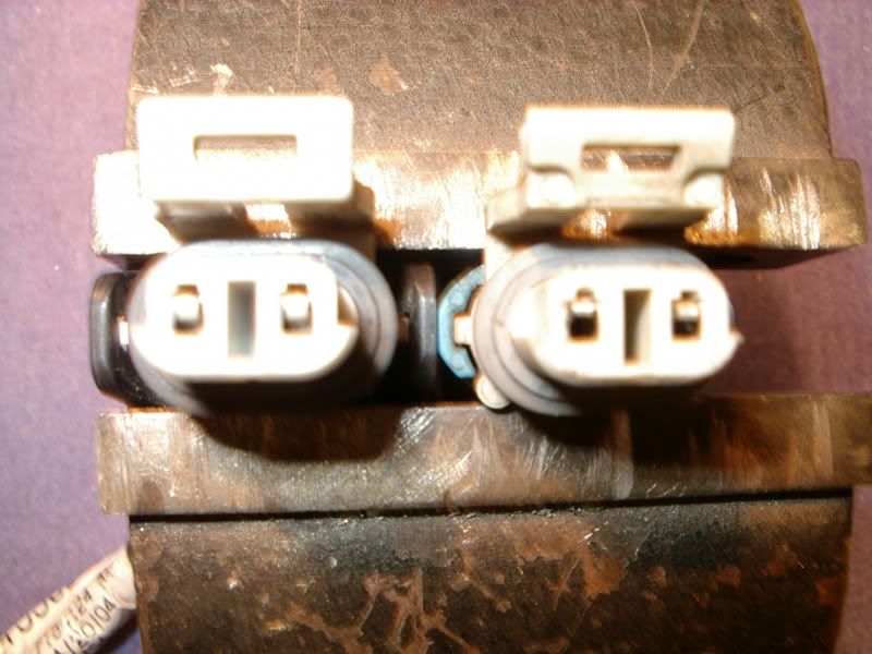
To correctly test the female pins you need a male pin that you can insert into the female pins to check for tension.
BC
It worked this time!!!! So,,you can see how its hooked up. My guess is that one or more of the female pins in the harness connector or the female connector on the frame that the jumper harness plugs into is not making proper connection.
GMs female pins are easily damaged and loose the spring tension necessary to grip the male pin properly due to age and vibration. They would have done us all a BIG favor if they used round cannon type aircraft style male and female pins.
Heres an example of a brand new and old damaged female connector with female pins off a C5 wheel speed sensor. The one on the left is NEW!!!
To correctly test the female pins you need a male pin that you can insert into the female pins to check for tension.
BC
Tech Contributor


Joined: Oct 1999
Posts: 41,013
Likes: 9,775
From: Charlotte, NC (formerly Endicott, NY)
Here is where the ESC Module is located:
Luggage compartment looking from rear of car

(1) Electronic Suspension Control (ESC) Module
(2) Rear Compartment Courtesy Lamp - Left
(3) Remote Playback Device - CD Changer
(4) Rear Compartment Courtesy Lamp - Right
(5) Rear Compartment Lid Ajar Switch
(6) Rear Compartment Lid Latch (Hardtop/Convertible)
Bill
Luggage compartment looking from rear of car
(1) Electronic Suspension Control (ESC) Module
(2) Rear Compartment Courtesy Lamp - Left
(3) Remote Playback Device - CD Changer
(4) Rear Compartment Courtesy Lamp - Right
(5) Rear Compartment Lid Ajar Switch
(6) Rear Compartment Lid Latch (Hardtop/Convertible)
Bill
Tech Contributor
Joined: Dec 1999
Posts: 32,910
Likes: 2,402
From: Anthony TX
CI 6,7,8,9,11 Vet
St. Jude Donor '08
Here is where the ESC Module is located:
Luggage compartment looking from rear of car
(1) Electronic Suspension Control (ESC) Module
(2) Rear Compartment Courtesy Lamp - Left
(3) Remote Playback Device - CD Changer
(4) Rear Compartment Courtesy Lamp - Right
(5) Rear Compartment Lid Ajar Switch
(6) Rear Compartment Lid Latch (Hardtop/Convertible)
Bill
Thanks for the guidance on posting those schematics!!!

Bill
Thread Starter
Safety Car
Joined: May 1999
Posts: 3,588
Likes: 1
From: Volcano, HI
Sooo... Come to find out that the previous owner had replaced the mag shocks with something else. The two rears were leaking, and rather than pay the $800 for the right ant $900 for the left, they replaced all four and put in some sort of kit to disable the ECM codes. Naturally, it didn't work. In all of the reading that I've done so far, I probably don't want F-55 anyway. What I really wanted was the Z51 that I had on my '02. Beggars can't be choosers... I just need to make the F-55 error codes go away for good.
Tech Contributor
Joined: Dec 1999
Posts: 32,910
Likes: 2,402
From: Anthony TX
CI 6,7,8,9,11 Vet
St. Jude Donor '08
Mojo
Find someone with a GM TECH II OR go to a dealer and you can have them DELETE the F-45 or F-55 RPO code from the BCM and you will be DONE WITH that crap!!! You can also remove all the F-45 crap from the car. NO MORE DTCs!! 
Then you can find a used set of Z51 or ZO6 sway bars with metal end links, ZO6 springs, add C6 ZO6 shocks and your car will handle like its on rails!!!!!
BC
Find someone with a GM TECH II OR go to a dealer and you can have them DELETE the F-45 or F-55 RPO code from the BCM and you will be DONE WITH that crap!!! You can also remove all the F-45 crap from the car. NO MORE DTCs!!
Then you can find a used set of Z51 or ZO6 sway bars with metal end links, ZO6 springs, add C6 ZO6 shocks and your car will handle like its on rails!!!!!
BC
Tech Contributor
Joined: Dec 1999
Posts: 32,910
Likes: 2,402
From: Anthony TX
CI 6,7,8,9,11 Vet
St. Jude Donor '08
Heres how to use the TECH II to turn OFF RPO Codes
Go to www.stopforce.com
Originally Posted by BlackZ06
These are instructions for a different RPO to be turned ON/OFF ... but note the F45 option in the last screen of the description of how to turn on Twilight Sentinal.
http://www.stopforce.com/RPO.html
WARNING - be certain you have already disconnected the computer that controls F45 before turning off this option. If you turn off the option with the computer still installed ... the next time you turn on the car the option will turn back ON automatically, requiring another visit to the dealer.
Thread Starter
Safety Car
Joined: May 1999
Posts: 3,588
Likes: 1
From: Volcano, HI
So, I disconnected all three plugs from the ESC, then took it in and had them delete RPO code F45. The service ride control no longer comes up, but it is still showing on "Maximum Speed: 80 MPH". The computer shows no error codes, which was confirmed with the Tech II. So now, I have no clue what to do. 