


Harmonic balancer separating? (see pictures)


Thread Starter
Pro


Joined: Mar 2006
Posts: 649
Likes: 3
From: Georgia
 Harmonic balancer separating? (see pictures)
Need advice: I noticed a loud racket coming from the front of my 99' coupe today. Looking down to where the harmonic balancer is located I noticed the belt about to come off so I quickly shut off the engine. It looks like the hub has moved on the harmonic balancer. It also looks like the other pulleys are no longer lined up with the grooves on the harmonic balancer.
I took some pictures. If someone can give me their opinion and if it looks like the harmonic balancer has separated. Also if so, what all is involved in replacing the HB. I have a 4 post lift and would like to do the repair if possible.
Thanks,
Vince

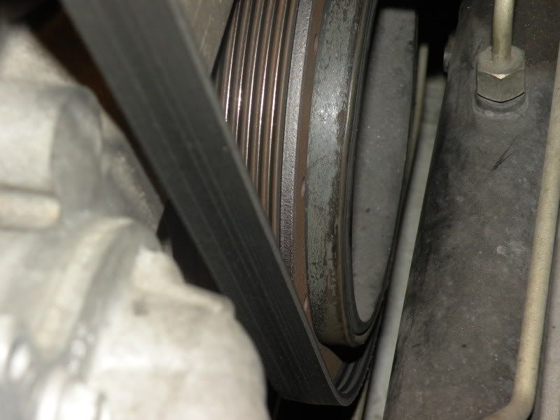

I took some pictures. If someone can give me their opinion and if it looks like the harmonic balancer has separated. Also if so, what all is involved in replacing the HB. I have a 4 post lift and would like to do the repair if possible.
Thanks,
Vince
Last edited by VinceAD; Aug 30, 2009 at 09:26 AM. Reason: content

Team Owner


Joined: Mar 1999
Posts: 22,025
Likes: 192
From: At the beach in little Rhody
Vince,
Its quite of bit of work but not hard. The steering rack has to come out to gain access. You should replace the timing cover seal while you are in there as well. With a lift, it will be a lot easier then it is for those of us who have to lay on our backs. If you have a stick, you can use the brakes and gears to hold the motor when you break the old bolt free. With an auto, buy the tool that holds the flywheel from turning. Make sure you follow the GM Service Manual on re-installation and don't follow the procedures on LS1howto.com as many guys have screwed up their crank threads following that web site. You can however, check it out for what is involved, just don't follow the procedures there for removal and installation of the HB.
Its quite of bit of work but not hard. The steering rack has to come out to gain access. You should replace the timing cover seal while you are in there as well. With a lift, it will be a lot easier then it is for those of us who have to lay on our backs. If you have a stick, you can use the brakes and gears to hold the motor when you break the old bolt free. With an auto, buy the tool that holds the flywheel from turning. Make sure you follow the GM Service Manual on re-installation and don't follow the procedures on LS1howto.com as many guys have screwed up their crank threads following that web site. You can however, check it out for what is involved, just don't follow the procedures there for removal and installation of the HB.
Le Mans Master


Joined: Jan 2007
Posts: 9,844
Likes: 33
From: S. FLA :: Professional Devil's Advocate
Here's a preview of the GM way of removing the balancer. Getting to it is kind of a pain as vettenuts mentioned. So much so, you may want to drop in a new cam as you've already removed 96% of what has to be moved to get to the cam.
Important
For manual transmission applications, note the position of the crankshaft balancer before removal. The balancer does not use a key or keyway for positioning. Mark or scribe the end of the crankshaft and the balancer before component removal. The crankshaft balancer must be installed to the original position. If replacing the crankshaft balancer, note the location of any existing balance weights, if applicable. Install new balance weights into the new crankshaft balancer, if applicable. Crankshaft balancer weights must be installed into the new balancer in the same location as the old balancer. A properly installed balance weight will be either flush or below flush with the face of the balancer.
Do not use the crankshaft balancer bolt again. Install a NEW crankshaft balancer bolt during final assembly.
Make sure that the teeth of the flywheel holding tool mesh with the teeth of the engine flywheel.
Install the J 42386-A and bolts. Use one M10-1.5 x 120 mm and one M10-1.5 x 45 mm bolt for proper tool operation. Tighten
Tighten the J 42386-A bolts to 50 N·m (37 lb ft).
Remove the crankshaft balancer bolt. Do not discard the crankshaft balancer bolt. The balancer bolt will be used during the balancer installation procedure.
Mark or scribe the crankshaft balancer and the end of the crankshaft. Note the balancer installed position on the crankshaft for assembly. Refer to Engine Balancing .
Use the J 41816 and the J 41816-2 in order to remove the crankshaft balancer.
Remove the J 42386-A and bolts.
Note the position of crankshaft balancer weights, if applicable.
Important
For manual transmission applications, note the position of the crankshaft balancer before removal. The balancer does not use a key or keyway for positioning. Mark or scribe the end of the crankshaft and the balancer before component removal. The crankshaft balancer must be installed to the original position. If replacing the crankshaft balancer, note the location of any existing balance weights, if applicable. Install new balance weights into the new crankshaft balancer, if applicable. Crankshaft balancer weights must be installed into the new balancer in the same location as the old balancer. A properly installed balance weight will be either flush or below flush with the face of the balancer.
Do not use the crankshaft balancer bolt again. Install a NEW crankshaft balancer bolt during final assembly.
Make sure that the teeth of the flywheel holding tool mesh with the teeth of the engine flywheel.
Install the J 42386-A and bolts. Use one M10-1.5 x 120 mm and one M10-1.5 x 45 mm bolt for proper tool operation. Tighten
Tighten the J 42386-A bolts to 50 N·m (37 lb ft).
Remove the crankshaft balancer bolt. Do not discard the crankshaft balancer bolt. The balancer bolt will be used during the balancer installation procedure.
Mark or scribe the crankshaft balancer and the end of the crankshaft. Note the balancer installed position on the crankshaft for assembly. Refer to Engine Balancing .
Use the J 41816 and the J 41816-2 in order to remove the crankshaft balancer.
Remove the J 42386-A and bolts.
Note the position of crankshaft balancer weights, if applicable.




Drifting


Joined: Nov 2003
Posts: 1,539
Likes: 3
From: South al
What yr car did that come off of ,that's the 1st one I've seen do that,gene culley is ur man www.gmpartshouse.com wholesale prices so it won't break the bank








