


Wheel Speed Sensor Codes

Thread Starter
Intermediate

Joined: May 2007
Posts: 33
Likes: 0
From: Miami Florida
Although I haven't pulled the plug out yet, I think I do see where it is, sitting snugly under the Power Steering fluid and radiator hose, in front of the 5.7L engine. Seems like a hostile and unlikely place to mount such a fragile piece of equipment!
But, seriously, looking at the diagram and photo you sent me:
I see labels as follows: LF WSS - "Signal", #11 (Lt. Blu) & LF WSS - "Low Ref" #25 (Yel).
Do these numbers, 11 & 25 hold the clues to help me to locate the pins I want to check? If the main connector pins are not numbered, how do you locate a particular pin number?
Update 4/30/10
I have decided to send my EBCM module in for rebuild to ATE for $50. After talking to 3 other rebuild places, ATE is the only one to say they can rebuild my type of problem. All the other guys said this is the one type of problem (no sensor input, 1221) they cannot fix due to unavailability of a chip. So wish me luck. I post the results when I get them. Git-R-Done!!!
Update 5/1/10 9AM
Wait!! Thanks to BC's excellent posting of the exact EBCM connector pin definitions, now I can easily test the signal input right at the point where it enters the EBCM! Awesome!!! Going to do this test and if it passes, then I send the the module in for rebuild; if it fails, then I know that somewhere between the hub and the EBCM, I am losing the signal. Man, this is great fun!
Last edited by jcorina; May 1, 2010 at 09:06 AM. Reason: Update

Tech Contributor


Joined: Dec 1999
Posts: 32,910
Likes: 2,402
From: Anthony TX
CI 6,7,8,9,11 Vet
St. Jude Donor '08
Connector Part Information
� C1 - 15401425
� 7-Way F Metri-Pack 480, GT 150 Mixed Series (BLK)
� C2 - 15356700
� 29 Way F Micro-Pack 100 Series (GRY)
Pin
Wire Color
Circuit No.
Function
A
RED
1642
Battery Positive Voltage
B
BRN
641
Ignition 3 voltage
C
GRY
1787
Variable Effort Steering Actuator High Effort Control
D
WHT
345
Variable Effort Steering Actuator Low Effort Control
E
--
--
Not Used
F
BLK/WHT
1251
Ground
G
BLK
1250
Ground
1
--
--
Not Used
2
TAN/BLK
464
Delivered Torque Signal
3
LT GRN
1763
Steering Wheel Position Signal A
4
--
--
Not Used
5
LT GRN/BLK
1338
Lateral Accelerometer Input (JL4)
6
LT BLU
20
Stop lamp Supply Voltage
7
--
--
Not Used
8
RED
885
Left Rear Wheel Speed Sensor Low Reference
9
BRN
882
Right Rear Wheel Speed Sensor Signal
10
DK GRN
872
Right Front Wheel Speed Sensor Signal
11
LT BLU
830
Left Front Wheel Speed Sensor Signa
12
ORN/BLK
463
Requested Torque Signal
13
ORN/BLK
556
Low Reference
14-16
--
--
Not Used
17
BLK
2626
Brake Pressure Sensor Signal (JL4)
18
LT BLU
1764
Steering Wheel Position Signal B
19
DK BLU
716
Yaw Rate Sensor Signal (JL4)
20
--
--
Not Used
21
LT BLU
1122
ABS/TCS Class 2 Serial Data
22
BLK
884
Left Rear Wheel Speed Sensor Signal
23
WHT
883
Right Rear Wheel Speed Sensor Low Reference
24
TAN
833
Right Front Wheel Speed Sensor Low Reference
25
YEL
873
Left Front Wheel Speed Sensor Low Reference
26
--
--
Not Used
27
GRY
1056
Steering Wheel Position Sensor 5V Reference Voltage
28
LT BLU
2627
Steering Position Sensor Signal
29
--
--
Not Used
Thread Starter
Intermediate
Joined: May 2007
Posts: 33
Likes: 0
From: Miami Florida
Wait!! Thanks to BC's excellent posting of the exact EBCM connector pin definitions, now I can easily test the signal input right at the point where it enters the EBCM! Awesome!!! Going to do this test and if it passes, then I send the the module in for rebuild; if it fails, then I know that somewhere between the hub and the EBCM, I am losing the signal. Man, this is great fun!
Tech Contributor
Joined: Dec 1999
Posts: 32,910
Likes: 2,402
From: Anthony TX
CI 6,7,8,9,11 Vet
St. Jude Donor '08
WAIT! 
NO ONE can fix that part of the EBTCM!!! All that the people who fix them do is replace the module power relay. Thats IT! So,,,,dont waste your cash unless you have a 1214 DTC. If the module is the issue (and I doubt if it is) you will need a NEW module from Gene Culley www.gmpartshouse.com Hes a WHOLE lot less cash than the dealer near you.
BC
Thread Starter
Intermediate
Joined: May 2007
Posts: 33
Likes: 0
From: Miami Florida
WAIT!
NO ONE can fix that part of the EBTCM!!! All that the people who fix them do is replace the module power relay. Thats IT! So,,,,dont waste your cash unless you have a 1214 DTC. If the module is the issue (and I doubt if it is) you will need a NEW module from Gene Culley www.gmpartshouse.com Hes a WHOLE lot less cash than the dealer near you.
BC
Thread Starter
Intermediate
Joined: May 2007
Posts: 33
Likes: 0
From: Miami Florida
I was able to perform a continuity test at pins 11 & 25 and it passed with flying colors. In other words, there is a closed circuit from my multimeter to the ABS wheel sensor and back again. That alone should be enough to prove there is signal getting to the EBCM since I performed the voltage test at two separate harness locations. Agree? Even so, I would like to do the voltage test again but have to figure out how to attach test leads to the connector that will stay put while I spin the wheel by myself. Your thoughts Bill?
Tech Contributor


Joined: Jan 2007
Posts: 19,493
Likes: 1,178
From: Dyer, IN
I was able to perform a continuity test at pins 11 & 25 and it passed with flying colors. In other words, there is a closed circuit from my multimeter to the ABS wheel sensor and back again. That alone should be enough to prove there is signal getting to the EBCM since I performed the voltage test at two separate harness locations. Agree? Even so, I would like to do the voltage test again but have to figure out how to attach test leads to the connector that will stay put while I spin the wheel by myself. Your thoughts Bill?
Corvette Stories
The Best of Corvette for Corvette Enthusiasts

Every 2027 Corvette Engine Explained
Joe Kucinski
Designer Imagines A Corvette That Looks More Like a Corvette Than the Corvette
Verdad Gallardo
10 Ugly Corvettes That We Still Kinda Love
Joe Kucinski
Top 10 Most Expensive Corvettes Ever Sold on Bring A Trailer
Brett Foote
10 Things Every Corvette Owner Needs (2026 Edition)
Michael S. Palmer
8 Most "Only Corvette Owners Understand" Quirks and Problems
Pouria Savadkouei
10 Reasons the C6 Z06 is Still A Performance Benchmark After 20 Years
Joe Kucinski
How Much Horsepower Every Corvette Engine "LOST" in 1972
Joe Kucinski
Top 10 DOs and DON'Ts for Protecting Your Convertible Top!
Michael S. Palmer
Thread Starter
Intermediate
Joined: May 2007
Posts: 33
Likes: 0
From: Miami Florida
Well, we wanted to make sure the harness connectors were making contact - that was our main concern. Doesn't a continuity test at least show that? If the harness connector wasn't making contact, wouldn't a failed continuity test be sufficient? Aren't we just talking about whether or not a wire is continuous or not here? I mean we're not testing a resister precisely, are we? Can you explain?
Thread Starter
Intermediate
Joined: May 2007
Posts: 33
Likes: 0
From: Miami Florida
Keep in my that previously, the voltage test passed. But maybe I'm not doing something right with the resistance test. I have a multimeter, a cheapo, but it has a fresh battery in it. I have the dial set on Ohms, 20M and before I place the leads on anything it reads "1". When I put the red and black leads on it changes to "0". If I put the dial on 20K, I get a reading of 1.11.
Tech Contributor
Joined: Jan 2007
Posts: 19,493
Likes: 1,178
From: Dyer, IN
Keep in my that previously, the voltage test passed. But maybe I'm not doing something right with the resistance test. I have a multimeter, a cheapo, but it has a fresh battery in it. I have the dial set on Ohms, 20M and before I place the leads on anything it reads "1". When I put the red and black leads on it changes to "0". If I put the dial on 20K, I get a reading of 1.11.
Reading resistance is more important, because a wire could have a high resistance value, yet still have good continuity.
If you are reading 1.1 K ohms through the sensor, that is good. If it does not include the sensor...that is a problem.
Thread Starter
Intermediate
Joined: May 2007
Posts: 33
Likes: 0
From: Miami Florida
On most DMM, a reading of "1" or "OL" indicates infinite resistance..or an open circuit. When checking continuity, the display should change to a 0, you can test this by simply touching the leads together. If it does not change, you do no have the meter set correct, leads are plugged in wrong, or have an issue with the leads.
Reading resistance is more important, because a wire could have a high resistance value, yet still have good continuity.
If you are reading 1.1 K ohms through the sensor, that is good. If it does not include the sensor...that is a problem.
Reading resistance is more important, because a wire could have a high resistance value, yet still have good continuity.
If you are reading 1.1 K ohms through the sensor, that is good. If it does not include the sensor...that is a problem.
Tech Contributor
Joined: Jan 2007
Posts: 19,493
Likes: 1,178
From: Dyer, IN

Thread Starter
Intermediate
Joined: May 2007
Posts: 33
Likes: 0
From: Miami Florida
I measured the resistance at the main EBCM harness connector at pins 11 & 25 and with my digital multimeter, got 1.1K ohms which falls within the specified range. The ABS Sensor harness coming out of the hub is plugged into the harness and the harness is plugged into the main wiring harness that goes on to the main EBCM connector where I did the test. (Previously, I performed the voltage test at the harness, spun the wheel hub around and the volts were in the specified range.)
Tech Contributor
Joined: Jan 2007
Posts: 19,493
Likes: 1,178
From: Dyer, IN
Sorry, not my intention. There three things to evaluate:
1) WSS output voltage
2) WSS resistance value (measured at the connector)
3) Resistance of the harness from the EBCM to the WSS connector.
1 is accomplished by measuring the ACmV output, which it sounds like you've done.
2 is accomplished by taking a resistance measurement at the WSS connector.
3 is accomplished by measuring the resistance of the harness from the EBCM. You can measure the individual wires (meter lead at each end), or install a jumper wire at the sensor disconnect, so you can evaluate the harness as a loop from the EBCM.
Thread Starter
Intermediate
Joined: May 2007
Posts: 33
Likes: 0
From: Miami Florida
Sorry, not my intention. There three things to evaluate:
1) WSS output voltage
2) WSS resistance value (measured at the connector)
3) Resistance of the harness from the EBCM to the WSS connector.
1 is accomplished by measuring the ACmV output, which it sounds like you've done.
2 is accomplished by taking a resistance measurement at the WSS connector.
3 is accomplished by measuring the resistance of the harness from the EBCM. You can measure the individual wires (meter lead at each end), or install a jumper wire at the sensor disconnect, so you can evaluate the harness as a loop from the EBCM.
1) WSS output voltage
2) WSS resistance value (measured at the connector)
3) Resistance of the harness from the EBCM to the WSS connector.
1 is accomplished by measuring the ACmV output, which it sounds like you've done.
2 is accomplished by taking a resistance measurement at the WSS connector.
3 is accomplished by measuring the resistance of the harness from the EBCM. You can measure the individual wires (meter lead at each end), or install a jumper wire at the sensor disconnect, so you can evaluate the harness as a loop from the EBCM.
The one thing I did not do is measure from the pins of the main EBCM connector to the end of the (unplugged at the hub) harness. Is this important? How could I have gotten the previous results without good wire between the main EBCM pins and the end of the harness? Should I do this test anyway? How is it different or unique to the others?
Tech Contributor
Joined: Dec 1999
Posts: 32,910
Likes: 2,402
From: Anthony TX
CI 6,7,8,9,11 Vet
St. Jude Donor '08
While your measuring resistance, have someone shake the harnesses and wiggle the connectors and see if that effects your reading. If it does, you have a intermittant/bad connection.
Bill
Bill
Thread Starter
Intermediate
Joined: May 2007
Posts: 33
Likes: 0
From: Miami Florida
OK, I'll try that. But as I mentioned before, I did purchase and install a brand new harness. Maybe I should buy one male and one female connector to make all the connections from the main EBCM Connector to the hub new. What do you think?
Tech Contributor
Joined: Dec 1999
Posts: 32,910
Likes: 2,402
From: Anthony TX
CI 6,7,8,9,11 Vet
St. Jude Donor '08
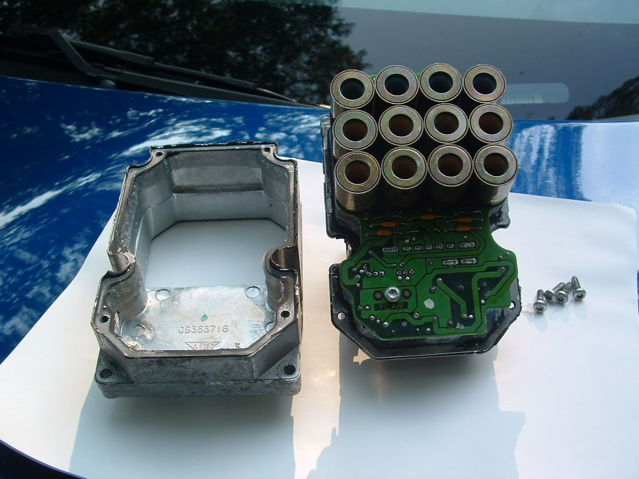
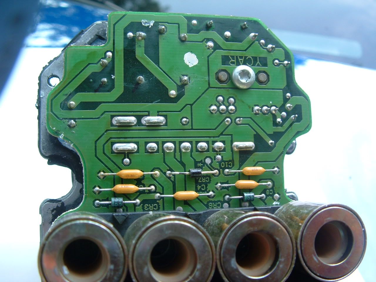
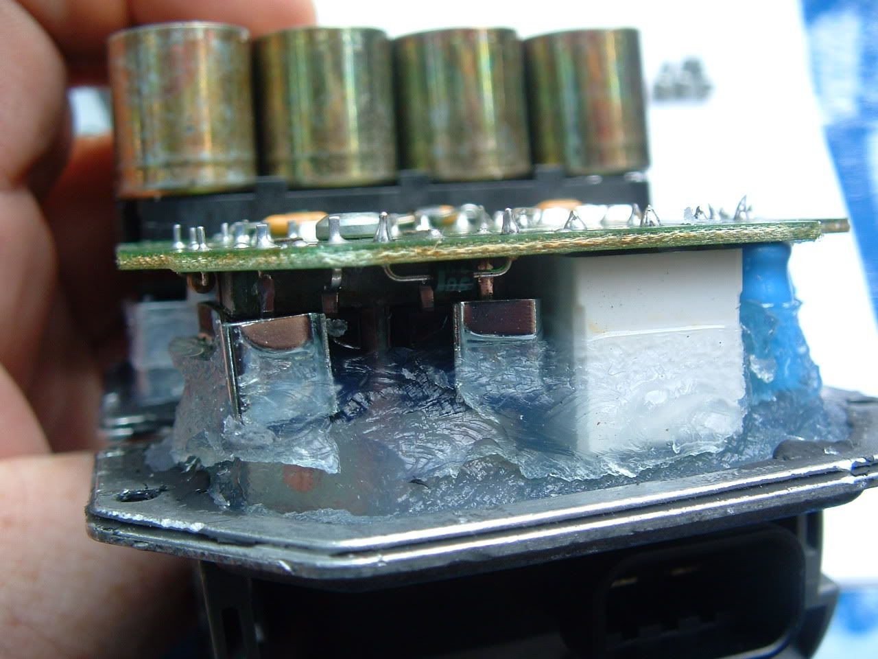
For the repair place that says that they can fix ANY EBTCM issue,,,,I have my serious doubts!
Heres the inside of one:
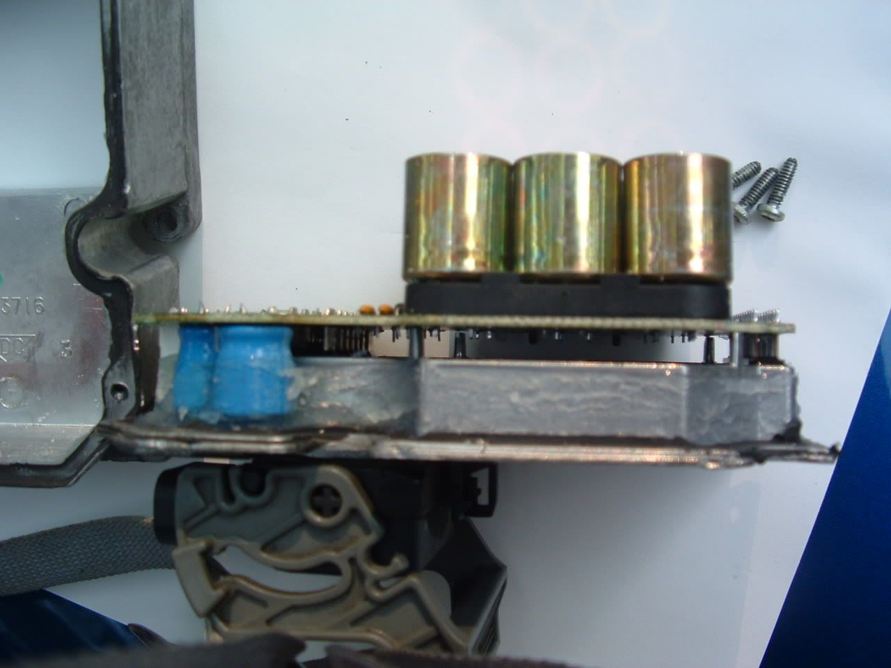
For the most part, its pretty simple and the circuit board components are fairly easy to replace and obtain. If you look UNDER the circuit board (down inside the aluminum tray) you will find a micro processor thats covered with a silicone gel. There NOT going to fix that micro processor if is bad.
You can give it a try. If theres something simple wrong with the circuit board, they may be able to fix it.
What is the model number of your EBTCM

BC
Heres the inside of one:
For the most part, its pretty simple and the circuit board components are fairly easy to replace and obtain. If you look UNDER the circuit board (down inside the aluminum tray) you will find a micro processor thats covered with a silicone gel. There NOT going to fix that micro processor if is bad.
You can give it a try. If theres something simple wrong with the circuit board, they may be able to fix it.
What is the model number of your EBTCM
BC