


Wheel Speed Sensor Codes

Thread Starter
Intermediate

Joined: May 2007
Posts: 33
Likes: 0
From: Miami Florida
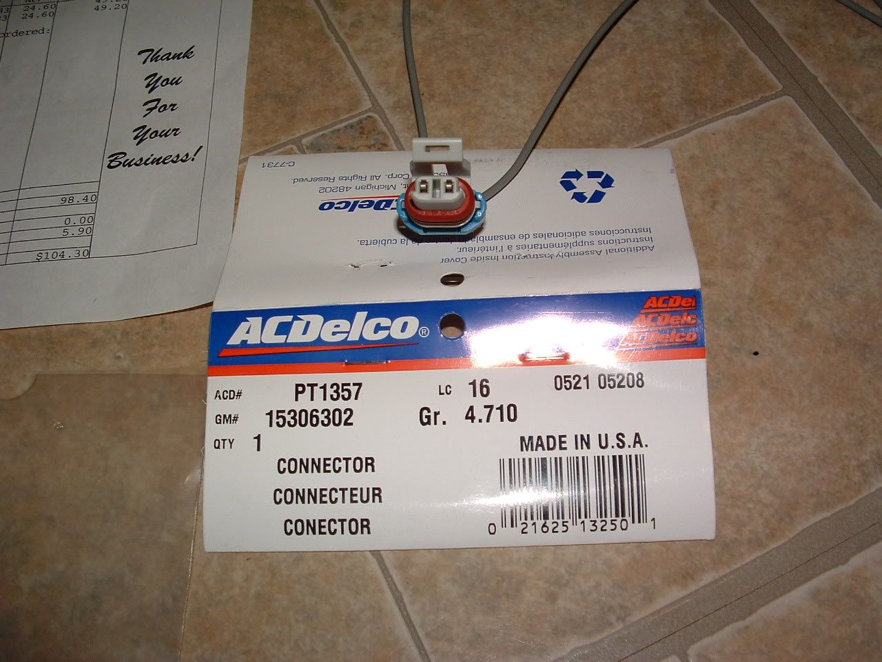
I'll could try one more thing: cut the wires at the end of the main harness connector and at the end of the hub connector and splice a new plain wire, bypassing / eliminating the connectors altogether. Then if the (no signal) code goes away, I could buy another ABS Sensor Harness (remember, I already have 1 new ABS Harness that I bought previously), and using the 2 new ends, rebuilt with all new (2m & 2f) connectors.
Tech Contributor


Joined: Jan 2007
Posts: 19,470
Likes: 1,171
From: Dyer, IN
I'll could try one more thing: cut the wires at the end of the main harness connector and at the end of the hub connector and splice a new plain wire, bypassing / eliminating the connectors altogether. Then if the (no signal) code goes away, I could buy another ABS Sensor Harness (remember, I already have 1 new ABS Harness that I bought previously), and using the 2 new ends, rebuilt with all new (2m & 2f) connectors.
Thread Starter
Intermediate
Joined: May 2007
Posts: 33
Likes: 0
From: Miami Florida
The above purpose is not just to avoid the multimeter or bypass the connectors but to eventually replace all the old connectors with new connectors whether or not it corrects the problem. Bottom line is I have checked the resistance and voltage at the main EBCM connector and both are OK but I still get a 1221 "No signal from LF ABS Sensor".

Tech Contributor


Joined: Dec 1999
Posts: 32,910
Likes: 2,402
From: Anthony TX
CI 6,7,8,9,11 Vet
St. Jude Donor '08
Try this
Read the Signal and Low Reff pins on the EBTCM for EACH wheel sensor and record the resistance for Signal input to Low Reff pins. They should ALL read the same resistance. If one of the readings is not the same, then the module is probably at fault.
Read the Signal and Low Reff pins on the EBTCM for EACH wheel sensor and record the resistance for Signal input to Low Reff pins. They should ALL read the same resistance. If one of the readings is not the same, then the module is probably at fault.
Thread Starter
Intermediate
Joined: May 2007
Posts: 33
Likes: 0
From: Miami Florida
With the DMM set to ohms, 2K, I get 1.116 for the left front (11,25) and I get 1.121 for the right front (10,24).
Last edited by jcorina; May 5, 2010 at 11:36 AM.
Thread Starter
Intermediate
Joined: May 2007
Posts: 33
Likes: 0
From: Miami Florida
I took a little trip up I-95 feeling a little bit frisky and got some new codes. In addition to the 28-TCS C1221, I got in addition, C1225 & C1283. I am still trying to interpret the slight difference in resistance I measured between left and right. (See previous post) I am hoping to save a few dollars and narrow it down to the cause. I have been to two different corvette specialty shops and one dealer and they all just want me to throw money at it by guessing what it is. One guy is 100% sure it's the wheel bearing and the other is 100% sure it's the EBCM module. And they all say the only way to know is to replace each part at my expense. Even the EBCM repair/replace people can't help because I understand all they can do is replace the power supply. The 1221 code came on and stayed on - it was never intermittant.
Tech Contributor
Joined: Dec 1999
Posts: 32,910
Likes: 2,402
From: Anthony TX
CI 6,7,8,9,11 Vet
St. Jude Donor '08
From the time that the C5 first appeared to now, I have NEVER seen a BAD Wheel Speed Sensor caused by a failure from something inside the sensor. I have seen the pig tail on the hub get ripped out but, zero internal failures I have seen a BAD Wheel Hub due to a bad bearing but, the bearing and sensor are two different parts The sensor is nothing more than a coil of wire wrapped on a plactic form and a toothed reluctor wheel on the hub shaft spins inside that coil of wire as the wheel turns. If you can read the coil resistance in the sensor/hub and spin the wheel and read the AC Signal that the sensor outputs, the sensor is GOOD Done even waste your money on a new one.
Your seeing "With the DMM set to ohms, 2K, I get 1.116 for the left front (11,25) and I get 1.121 for the right front (10,24). "
That would be 1116 ohms and 1121 ohms. The difference is most likley the distance in wiring harness length.
You need to have someone shake the harness while you read the resistance to make sure that you dont have an intermittant or flukey connection due to poor female connector pins. Thats the MOST COMMON WSS failure issue.
BC
Thread Starter
Intermediate
Joined: May 2007
Posts: 33
Likes: 0
From: Miami Florida
From the time that the C5 first appeared to now, I have NEVER seen a BAD Wheel Speed Sensor caused by a failure from something inside the sensor. I have seen the pig tail on the hub get ripped out but, zero internal failures I have seen a BAD Wheel Hub due to a bad bearing but, the bearing and sensor are two different parts The sensor is nothing more than a coil of wire wrapped on a plactic form and a toothed reluctor wheel on the hub shaft spins inside that coil of wire as the wheel turns. If you can read the coil resistance in the sensor/hub and spin the wheel and read the AC Signal that the sensor outputs, the sensor is GOOD Done even waste your money on a new one.
Your seeing "With the DMM set to ohms, 2K, I get 1.116 for the left front (11,25) and I get 1.121 for the right front (10,24). "
That would be 1116 ohms and 1121 ohms. The difference is most likley the distance in wiring harness length.
You need to have someone shake the harness while you read the resistance to make sure that you dont have an intermittant or flukey connection due to poor female connector pins. Thats the MOST COMMON WSS failure issue.
BC
Your seeing "With the DMM set to ohms, 2K, I get 1.116 for the left front (11,25) and I get 1.121 for the right front (10,24). "
That would be 1116 ohms and 1121 ohms. The difference is most likley the distance in wiring harness length.
You need to have someone shake the harness while you read the resistance to make sure that you dont have an intermittant or flukey connection due to poor female connector pins. Thats the MOST COMMON WSS failure issue.
BC
Corvette Stories
The Best of Corvette for Corvette Enthusiasts

Top 10 Most Expensive Corvettes Ever Sold on Bring A Trailer
Brett Foote
10 Things Every Corvette Owner Needs (2026 Edition)
Michael S. Palmer
8 Most "Only Corvette Owners Understand" Quirks and Problems
Pouria Savadkouei
10 Reasons the C6 Z06 is Still A Performance Benchmark After 20 Years
Joe Kucinski
How Much Horsepower Every Corvette Engine "LOST" in 1972
Joe Kucinski
Top 10 DOs and DON'Ts for Protecting Your Convertible Top!
Michael S. Palmer
Top 10 Most Explosive Corvettes Ever Made: Power-to-Weight Ratio Ranked!
Joe Kucinski
150 hp to 1,250 hp: Every Corvette Generation Compared by the Specs That Matter
Joe Kucinski
8 Coolest Corvette Pace Cars (and Replicas) of All Time
Verdad Gallardo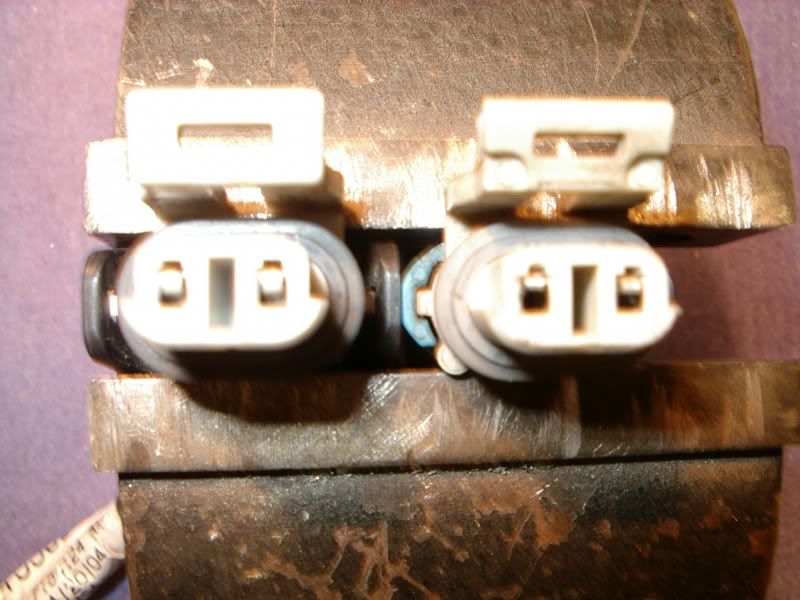
Tech Contributor


Joined: May 2008
Posts: 2,843
Likes: 16
From: Howell Michigan
St. Jude Donor '09-'10-'11
Hmm, learn something every day...I didn't know you could take them apart without damage.
OP, if you end up repairing yours some photos of ther repair would be interesting to see.
OP, if you end up repairing yours some photos of ther repair would be interesting to see.
Pro


Joined: Nov 2002
Posts: 599
Likes: 16
From: vista CA
I am also chasing this stuff - started right after removing steering rack and repositioning EBCM to change harmonic balancer.
I agree connectors most likely culprits (including the ground connections) - and that is what is on my agenda for tomorrow (the schematics here will help alot) - but was also thinking after seeing BC's picture of the EBCM circuit board - HAS ANYBODY HEARD OF COLD SOLDER JOINTS ON THE EBCM BEING AN ISSUE? After all, I have had to deal with those 'failures' in both the HVAC control head and the key fobs......

I agree connectors most likely culprits (including the ground connections) - and that is what is on my agenda for tomorrow (the schematics here will help alot) - but was also thinking after seeing BC's picture of the EBCM circuit board - HAS ANYBODY HEARD OF COLD SOLDER JOINTS ON THE EBCM BEING AN ISSUE? After all, I have had to deal with those 'failures' in both the HVAC control head and the key fobs......
Tech Contributor
Joined: Dec 1999
Posts: 32,910
Likes: 2,402
From: Anthony TX
CI 6,7,8,9,11 Vet
St. Jude Donor '08
I am also chasing this stuff - started right after removing steering rack and repositioning EBCM to change harmonic balancer.
I agree connectors most likely culprits (including the ground connections) - and that is what is on my agenda for tomorrow (the schematics here will help alot) - but was also thinking after seeing BC's picture of the EBCM circuit board - HAS ANYBODY HEARD OF COLD SOLDER JOINTS ON THE EBCM BEING AN ISSUE? After all, I have had to deal with those 'failures' in both the HVAC control head and the key fobs......
I agree connectors most likely culprits (including the ground connections) - and that is what is on my agenda for tomorrow (the schematics here will help alot) - but was also thinking after seeing BC's picture of the EBCM circuit board - HAS ANYBODY HEARD OF COLD SOLDER JOINTS ON THE EBCM BEING AN ISSUE? After all, I have had to deal with those 'failures' in both the HVAC control head and the key fobs......
 When I got my EBTCM apart, I took it to a 2M Micro Minature Module Repair station and put it under the micro scope and Ive see 6 year old kids solder better.
  DELPHI soldering SUCKS! Could very well be a poor solder joint.
BC

Instructor
Joined: Sep 2019
Posts: 114
Likes: 15
I already did that and didn't see any changes. I performed resistance and voltage tests from the hub; from the end of the ABS Sensor harness; and from the main connector PINS at the EBCM; and I did it while wiggle the wires. All tests results were within factory specs.
The above purpose is not just to avoid the multimeter or bypass the connectors but to eventually replace all the old connectors with new connectors whether or not it corrects the problem. Bottom line is I have checked the resistance and voltage at the main EBCM connector and both are OK but I still get a 1221 "No signal from LF ABS Sensor".
The above purpose is not just to avoid the multimeter or bypass the connectors but to eventually replace all the old connectors with new connectors whether or not it corrects the problem. Bottom line is I have checked the resistance and voltage at the main EBCM connector and both are OK but I still get a 1221 "No signal from LF ABS Sensor".