


Electrical Voltage question(s)
Drifting


Joined: Mar 2010
Posts: 1,628
Likes: 15
From: Seattle WA
So all cleaned up, the contacts now look like:
Put it back together. Drive around.
P1221 throws again as I'm driving home from work. That throws Reduced Engine Power.
Still not fixed.
VERY frustrating!!!!
So here is the list of what has been done:
Ignition switch cleaned
Battery Replaced
Grounds grounded
TPS sensor replaced
TB replaced
The loom going to the TPS has been checked. Tested the pins for grip, etc....no bare wire on the loom, etc...
What the hell else can I try? ANY suggestions will be considered!!!
I think your ignition switch was exacerbating a problem at your starter. Clean up your connections there, and I think you'll be golden.
Disregard everything I said above if your alternator to battery jumper is still in place.
Thread Starter
Advanced

Joined: Aug 2007
Posts: 69
Likes: 0
From: Albuquerque New Mexico
Peerpsi,
Yes it does have an aftermarket stereo, amps, sub, and a capacitor (which conveniently shows me pretty darn close to actual battery amperage!)
Concerning the fact that this seems to happen during low voltage moments,
The DIC showed 13.1 (sorry for the blur, I was either driving, or shaking from anger at that time!):
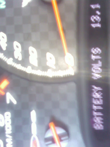
While the AMP showed:
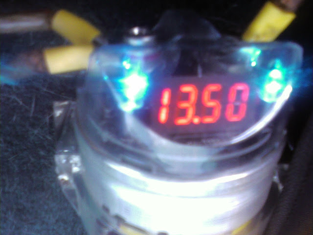
The stereo system HAS been taken out of the loop several times to try to isolate this issue. To no avail!
Yes it does have an aftermarket stereo, amps, sub, and a capacitor (which conveniently shows me pretty darn close to actual battery amperage!)
Concerning the fact that this seems to happen during low voltage moments,
The DIC showed 13.1 (sorry for the blur, I was either driving, or shaking from anger at that time!):
While the AMP showed:
The stereo system HAS been taken out of the loop several times to try to isolate this issue. To no avail!
Thread Starter
Advanced
Joined: Aug 2007
Posts: 69
Likes: 0
From: Albuquerque New Mexico
Thanks TRIOS! Yes, the jumper is gone. Didn't like driving with that for long! I will start looking at the starter connections next I guess! Its something I haven't done yet!
Pro


Joined: Aug 2010
Posts: 545
Likes: 4
From: Calgary Alberta
Consider taking your alternator to your local parts store or repair shop for testing.
The suggestion regarding relays is a good one. I design electrical equipment for a living and I can tell you that systems are designed to meet the known loads, possible grow of loads and a budget. The budget dictates that we don't build it much bigger then it needs to be. If you start adding high power loads like amps and stereos you need to consider how that power is routed. Precautions should be taken to ensure those new loads don't run through the ignition switch or other relay/contact points. The best way to do it would be to consider the load, select the appropriate wire size and protect the wire with the appropriately sized fuse. To control the circuits with the ignition switch install properly sized relays/contactors to switch the loads. Power the coil for the relay via the ignition switch.
The suggestion regarding relays is a good one. I design electrical equipment for a living and I can tell you that systems are designed to meet the known loads, possible grow of loads and a budget. The budget dictates that we don't build it much bigger then it needs to be. If you start adding high power loads like amps and stereos you need to consider how that power is routed. Precautions should be taken to ensure those new loads don't run through the ignition switch or other relay/contact points. The best way to do it would be to consider the load, select the appropriate wire size and protect the wire with the appropriately sized fuse. To control the circuits with the ignition switch install properly sized relays/contactors to switch the loads. Power the coil for the relay via the ignition switch.
Pro
Joined: Aug 2010
Posts: 545
Likes: 4
From: Calgary Alberta
The code you state P1221 is for Throttle positions sensor. That does not function on the 13.2 VDC nominal system voltage. It runs off the 5 volt reference. Even if your battery/charge system is moderately low the 5 volts will be coming from a DC/DC converter on some circuit board some where. It would not likely be the problem. From looking at the schematic everything is referenced to ground so that could well be the problem. As for the TPS sensor I'd check the connector for clean contacts. Given that it's an intermittent problem the sensor is probably fine but you have a bad connection somewhere. The sensor can be tested with an ohm meter as it is simply a potentiometer.
Pro
Joined: Aug 2010
Posts: 545
Likes: 4
From: Calgary Alberta
See quotes from service manual below for your trouble code. Quite often with 5 volt reference equipment will fail due to the 5 volt reference being out of spec. Generally speaking that is only with the digital functions, limit switches that type of thing. The TPS is an analouge device with what appears to be a redundant system to ensure no false readings. My guess is the engineers designed in a failure code if the two signals don't add up as the should. Check the TPS connector for corrosion.
DTC P1221
Circuit Description
The throttle position (TP) sensor is mounted on the throttle body assembly. The sensor is actually 2 individual TP sensors within 1 housing. Two separate signal, low reference and 5 volt reference circuits are used in order to connect the TP sensor assembly to the throttle actuator control (TAC) module. The 2 sensors have opposite functionality. The TP sensor 1 signal voltage is pulled up to the reference voltage as the throttle opens, from below 1 volt at closed throttle to above 3.5 volts at wide open throttle (WOT). The TP sensor 2 signal voltage is pulled down to the low reference from around 3.8 volts at closed throttle to below 1 volt at WOT. TP sensor 1 and APP sensor 1 share a 5-volt reference circuit that is connected within the TAC module. TP sensor 2 and APP sensor 2 share a 5-volt reference circuit that is connected within the TAC module. If an out of range condition is detected with the TP sensors, this DTC will set and the Reduced Engine Power message will be displayed.
Conditions for Running the DTC
DTCs P1517, or P1518 are not set.
The ignition switch is in the crank or run position.
The ignition voltage is greater than 5.23 volts.
Conditions for Setting the DTC
TP sensor 2 disagrees with TP sensor 1 by more than 7.5 percent.
All above conditions are present for less than 1 second.
Action Taken When the DTC Sets
The control module illuminates the malfunction indicator lamp (MIL) when the diagnostic runs and fails.
The control module records the operating conditions at the time the diagnostic fails. The control module stores this information in the Freeze Frame and/or the Failure Records.
The control module commands the TAC system to operate in the Reduced Engine Power mode.
A message center or an indicator displays Reduced Engine Power.
Under certain conditions the control module commands the engine OFF.
Conditions for Clearing the MIL/DTC
The control module turns OFF the malfunction indicator lamp (MIL) after 3 consecutive ignition cycles that the diagnostic runs and does not fail.
A current DTC, Last Test Failed, clears when the diagnostic runs and passes.
A history DTC clears after 40 consecutive warm-up cycles, if no failures are reported by this or any other emission related diagnostic.
Clear the MIL and the DTC with a scan tool.
Diagnostic Aids
Inspect the TAC module connectors for signs of water intrusion. When water intrusion occurs, multiple DTCs could be set with no DTC circuit or component conditions found during diagnostic testing.
When the TAC module detects a condition within the TAC system, more than 1 TAC system related DTC may set. This is due to the many redundant tests that run continuously on this system. Locating and repairing 1 individual condition may correct more than 1 DTC. Disconnecting components during testing may set additional DTCs. Keep this in mind when reviewing the stored information, Capture info.
If this DTC is determined to be intermittent, refer to Intermittent Conditions .
Test Description
The numbers below refer to the step numbers on the diagnostic table.
When the TAC module detects a condition within the TAC system, more than 1 TAC system related DTC may set. This is due to the many redundant tests that run continuously on this system. Locating and repairing 1 individual condition may correct more than 1 DTC. Disconnecting components during testing may set additional DTCs. Keep this in mind when reviewing the stored information, Capture info.
Step
Action
Yes
No
Schematic Reference: Engine Controls Schematics
Connector End View References: Powertrain Control Module (PCM) Connector End Views , Throttle Actuator Control (TAC) Module Connector End Views , or Engine Controls Connector End Views
1
Did you perform the Diagnostic System Check-Engine Controls?
Go to Step 2
Go to Diagnostic System Check - Engine Controls
2
Is DTC P1518 also set?
Go to Diagnostic Trouble Code (DTC) List
Go to Step 3
3
Turn ON the ignition, with the engine OFF.
With a scan tool, observe the TP sensor 1 and 2 Agree/Disagree parameter.
Does the scan tool TP sensor 1 and 2 Agree/Disagree parameter indicate Disagree?
Go to Step 5
Go to Step 4
4
Remove the air inlet duct from the throttle body.
Disconnect the throttle actuator motor harness connector.
Slowly manually open the throttle blade to WOT and back to the closed throttle position several times while observing the scan tool TP sensor Agree/Disagree parameter.
Does the TP sensor Agree/Disagree parameter change from Agree to Disagree during the above test?
Go to Step 18
Go to Step 5
5
Disconnect the TP sensor harness connector.
Disconnect the TAC module harness connectors.
Test the TP sensor 1 5-volt reference circuit for resistance. Refer to Circuit Testing and Wiring Repairs in Wiring Systems.
Did you find and correct the condition?
Go to Step 20
Go to Step 6
6
With a DMM, test for a short between the TP sensor 1 5-volt reference circuit and all other TAC module circuits. Refer to Circuit Testing and Wiring Repairs in Wiring Systems.
Did you find and correct the condition?
Go to Step 20
Go to Step 7
7
With a DMM, test the TP sensor 1 signal circuit for resistance. Refer to Circuit Testing and Wiring Repairs in Wiring Systems.
Did you find and correct the condition?
Go to Step 20
Go to Step 8
8
With a DMM, test for a short between the TP sensor 1 signal circuit and all other TAC module circuits. Refer to Circuit Testing and Wiring Repairs in Wiring Systems.
Did you find and correct the condition?
Go to Step 20
Go to Step 9
9
With a DMM, test the TP sensor 1 low reference circuit for resistance. Refer to Circuit Testing and Wiring Repairs in Wiring Systems.
Did you find and correct the condition?
Go to Step 20
Go to Step 10
10
With a DMM, test for a short between the TP sensor 1 low reference circuit and all other TAC module circuits. Refer to Circuit Testing and Wiring Repairs in Wiring Systems.
Did you find and correct the condition?
Go to Step 20
Go to Step 11
11
With a DMM, test the TP sensor 2 5-volt reference circuit for resistance. Refer to Circuit Testing and Wiring Repairs in Wiring Systems.
Did you find and correct the condition?
Go to Step 20
Go to Step 12
12
With a DMM, test for a short between the TP sensor 2 5-volt reference circuit and all other TAC module circuits. Refer to Circuit Testing and Wiring Repairs in Wiring Systems.
Did you find and correct the condition?
Go to Step 20
Go to Step 13
13
With a DMM, test the TP sensor 2 signal circuit for resistance. Refer to Circuit Testing and Wiring Repairs in Wiring Systems.
Did you find and correct the condition?
Go to Step 20
Go to Step 14
14
With a DMM, test for a short between the TP sensor 2 signal circuit and all other TAC module circuits. Refer to Circuit Testing and Wiring Repairs in Wiring Systems.
Did you find and correct the condition?
Go to Step 20
Go to Step 15
15
With a DMM, test the TP sensor 2 low reference circuit for resistance. Refer to Circuit Testing and Wiring Repairs in Wiring Systems.
Did you find and correct the condition?
Go to Step 20
Go to Step 16
16
With a DMM, test for a short between the TP sensor 2 low reference circuit and all other TAC module circuits. Refer to Circuit Testing and Wiring Repairs in Wiring Systems.
Did you find and correct the condition?
Go to Step 20
Go to Step 17
17
Inspect for poor connections at the harness connector of the TAC module. Refer to Testing for Intermittent and Poor Connections and Repairing Connector Terminals in Wiring Systems.
Did you find and correct the condition?
Go to Step 20
Go to Step 18
18
Inspect for poor connections at the harness connector of the TP sensor. Refer to Testing for Intermittent and Poor Connections and Repairing Connector Terminals in Wiring Systems.
Did you find and correct the condition?
Go to Step 20
Go to Step 19
19
Important
The throttle position sensor is not a serviceable part and should only be replaced with the throttle body assembly.
Replace the throttle body assembly. Refer to Throttle Body Assembly Replacement .
Did you complete the replacement?
Go to Step 20
--
20
Use a scan tool in order to clear the DTCs.
Turn OFF the ignition for 30 seconds.
Start the engine.
Operate the vehicle within the Conditions for Running the DTC as specified in the supporting text.
Does the DTC run and pass?
Go to Step 21
Go to Step 2
21
With a scan tool, observe the stored information, Capture Info.
Does the scan tool display any DTCs that you have not diagnosed?
Go to Diagnostic Trouble Code (DTC) List
System OK
Drifting
Joined: Mar 2010
Posts: 1,628
Likes: 15
From: Seattle WA
People worry too much. I have a massive unfused 2/0 cable in my diesel rig connecting the two batteries, which are on opposite sides of the truck. Came this way from the factory (well, unfused, but it was a smaller gauge). Many thousands of similar trucks around with the same setup, and I don't hear of diesels burning from electrical fires all THAT often...
Corvette Stories
The Best of Corvette for Corvette Enthusiasts

5 Best & 5 Worst Corvette Daily Drivers
Joe Kucinski
The Headlights of Every Corvette Generation Explained
Joe Kucinski
5 Best & 5 Most Overrated Corvette Track Packages of All Time!
Joe Kucinski
Every 2027 Corvette Engine Explained
Joe Kucinski
Designer Imagines A Corvette That Looks More Like a Corvette Than the Corvette
Verdad Gallardo
10 Ugly Corvettes That We Still Kinda Love
Joe Kucinski
Top 10 Most Expensive Corvettes Ever Sold on Bring A Trailer
Brett Foote
10 Things Every Corvette Owner Needs (2026 Edition)
Michael S. Palmer
8 Most "Only Corvette Owners Understand" Quirks and Problems
Pouria SavadkoueiPro
Joined: Aug 2010
Posts: 545
Likes: 4
From: Calgary Alberta
People worry too much. I have a massive unfused 2/0 cable in my diesel rig connecting the two batteries, which are on opposite sides of the truck. Came this way from the factory (well, unfused, but it was a smaller gauge). Many thousands of similar trucks around with the same setup, and I don't hear of diesels burning from electrical fires all THAT often...
Tech Contributor


Joined: Jan 2007
Posts: 19,518
Likes: 1,189
From: Dyer, IN
People worry too much. I have a massive unfused 2/0 cable in my diesel rig connecting the two batteries, which are on opposite sides of the truck. Came this way from the factory (well, unfused, but it was a smaller gauge). Many thousands of similar trucks around with the same setup, and I don't hear of diesels burning from electrical fires all THAT often...

Racer

Joined: May 2008
Posts: 316
Likes: 0
From: San Deigo California
If the voltage stays low when it's hot then you can measure where the voltage drop is. For example, what is voltage difference from battery negative terminal and the chassis. It should be totally zero, but if a sensative meter shows 0.1 volt, you have a problem. Ditto for measuring other points.
It is not an alternator problem. If voltage dropped that low it would mean the battery is not charged and the car would not start.
I used to wire race cars.
It is not an alternator problem. If voltage dropped that low it would mean the battery is not charged and the car would not start.
I used to wire race cars.
Thread Starter
Advanced
Joined: Aug 2007
Posts: 69
Likes: 0
From: Albuquerque New Mexico
What a lot of great suggestions! Here's my answers so far, starting backwards!
Rmarks: The meter we're using goes ohms to hundreds (0.00). Haven't checked all the grounds for that, but negative and the primary grounds are all 0.
Lucky: I was wondering when someone would say something about the beer can fix! That's some tried and true hillbilly engineering right thar! And seeing as how this other problem is a little more important, I'll get the welding done later!
Peerpsi: That's a lot of great info! We have gone through all of those troubleshooting steps on THREE different TPS sensors! The pins/connectors and cable have all been thoroughly checked. IS there anyway to actually monitor that 5volt system while driving?
The alternator has been tested clean. It was on the O'Riely auto store meter so I'm not 100% confident on that, but am thinking the jumper should have mostly ruled that out.
Okay, modifications question! This car has a NEW (rebuilt) engine! It was done last summer. Long story and lots of drama (and money). But it was okay all winter (still wondering about the heat issues). This seemed to start as it got hotter out.
Next thing: Low Engine Oil is still popping on all the time. The oil is good, and the sensor has been replaced. I believe (please correct me if I'm wrong) that that sensor goes to the starter area, which leads me to believe that's a good thing to tackle next.
And another piece of info, I definitely felt it surge/hesitate right before the code was thrown. Probably just as the tps went out of whack, but it is a physical sensation before the engine cuts out at Reduced Power.
Going to check starter area and cables this weekend. Will report and hopefully have more fun pics!
Rmarks: The meter we're using goes ohms to hundreds (0.00). Haven't checked all the grounds for that, but negative and the primary grounds are all 0.
Lucky: I was wondering when someone would say something about the beer can fix! That's some tried and true hillbilly engineering right thar!
And seeing as how this other problem is a little more important, I'll get the welding done later!Peerpsi: That's a lot of great info! We have gone through all of those troubleshooting steps on THREE different TPS sensors! The pins/connectors and cable have all been thoroughly checked. IS there anyway to actually monitor that 5volt system while driving?
The alternator has been tested clean. It was on the O'Riely auto store meter so I'm not 100% confident on that, but am thinking the jumper should have mostly ruled that out.
Okay, modifications question! This car has a NEW (rebuilt) engine! It was done last summer. Long story and lots of drama (and money). But it was okay all winter (still wondering about the heat issues). This seemed to start as it got hotter out.
Next thing: Low Engine Oil is still popping on all the time. The oil is good, and the sensor has been replaced. I believe (please correct me if I'm wrong) that that sensor goes to the starter area, which leads me to believe that's a good thing to tackle next.
And another piece of info, I definitely felt it surge/hesitate right before the code was thrown. Probably just as the tps went out of whack, but it is a physical sensation before the engine cuts out at Reduced Power.
Going to check starter area and cables this weekend. Will report and hopefully have more fun pics!
Pro
Joined: Aug 2010
Posts: 545
Likes: 4
From: Calgary Alberta
It would be difficult to monitor the 5 volts while running. I doubt that is your problem though. The diagnostics text I posted states that the TPS faults when the signals disagree by 7.5%. That means a difference of .39 volts. You say you've checked the TPS sensors, have you ohmed out the harness? Looking at the schematics it appears there is a connector at the TAC module and one at the TPS. Intermittent faults that increase in frequency when temperatures rise is often due to poor connections or damaged wiring. The reason is a positive temperature coefficient. In other words the resistance increases with heat. Increased resistance means less current conducted or with sensor circuits more voltage dropped across the fault resulting in a reduced voltage seen at the sensing circuit. Looking at the schematic a ground is not involved in the TPS itself but it is involved in bringing power to the TAC unit.

Tech Contributor


Joined: Dec 1999
Posts: 32,910
Likes: 2,402
From: Anthony TX
CI 6,7,8,9,11 Vet
St. Jude Donor '08
Have you inspected the ENGINE WIRING HARNESS on the drivers side of the engine for chaffing where it bends around the metal bracket at the back of the fuel rail???
Very common issue:

Very common issue:
Drifting
Joined: Mar 2010
Posts: 1,628
Likes: 15
From: Seattle WA
90 degree rated 2/0 cable in free air is rated for 285 amps. Probably a safe bet that your batteries in a fault condition are not going to flow enough current for enough time to burn that cable up. Conversely 10 gauge 90 degree rated cable is rated for 40 amps. Clearly the batteries could provide enough current to create a problem with that wire. A $5 dollar fuse is a lot cheaper then a car!
Drifting
Joined: Mar 2010
Posts: 1,628
Likes: 15
From: Seattle WA
There is nothing wrong with making sure someone knows the risks involved
.....especially when the person in question may already practice questionable maintenance/repairs......the OP has a beer can on his header pipe to repair a leak.....
Pro
Joined: Aug 2010
Posts: 545
Likes: 4
From: Calgary Alberta
At the end of the day you do not want to bypass or remove fuses or fused links. As a short term test perhaps but not permanently.
Thread Starter
Advanced
Joined: Aug 2007
Posts: 69
Likes: 0
From: Albuquerque New Mexico
Just above the starter, is this connector:
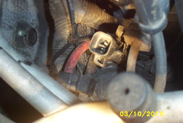
Looks like a bent pin and has never been connected. Or not since the engine swap last year anyway. Anyone have any idea what this is and what connects to it?
Looks like a bent pin and has never been connected. Or not since the engine swap last year anyway. Anyone have any idea what this is and what connects to it?
Thread Starter
Advanced
Joined: Aug 2007
Posts: 69
Likes: 0
From: Albuquerque New Mexico
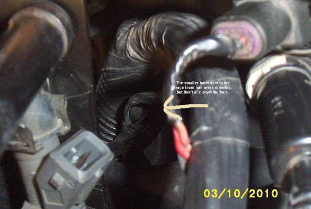
Bill,
I had not noticed this side before, but checking I see that the smaller loom looks as though there are wires, but none seem bare. Is there a trick into getting in there?
I had not noticed this side before, but checking I see that the smaller loom looks as though there are wires, but none seem bare. Is there a trick into getting in there?