


My turn in C5 electrical hell.
Melting Slicks


Joined: Nov 1999
Posts: 2,347
Likes: 857
From: MI
Cruise-In VI Veteran
DTC B2578 Right Front Turn Signal Monitor Circuit
Circuit Description
The BCM monitors the RF turn signal circuit in order to determine the status of the turn signal switch. If the BCM detects an oscillating voltage on CKT 15, the BCM interprets this as a RF turn signal ON request from the turn signal switch. The BCM will de-energize the RH DRL relay, which will disable the RF turn signal lamp (which is ON for the DRL), thus allowing the RF turn signal to flash. If the BCM does not detect an oscillating voltage on CKT 15, the BCM interprets this as the RF turn signal being OFF. The BCM will then energize the RH DRL relay and continue normal DRL operation. The BCM monitors the RF turn signal CKT 15 and determines how long voltage is applied. If the voltage is applied for longer than expected, a malfunction is present and a DTC will set.
Conditions for Setting the DTC
� The BCM detects continuous battery voltage on the RF turn signal monitor circuit (CK 15).
� The condition must be present for longer than 5 seconds.
Action Taken When the DTC Sets
� Stores a DTC B2578 in the BCM memory.
� No driver warning message will be displayed for this DTC.
Conditions for Clearing the DTC
� This DTC requires an ignition cycle in order to change from current to history.
� The BCM no longer detects continuous battery voltage on the RF turn signal monitor circuit (CKT 15) for longer than 5 seconds.
� A history DTC will clear after 50 consecutive ignition cycles if the condition for the malfunction is no longer present.
� Use the IPC clearing DTCs feature.
� Use a scan tool.
Diagnostic Aids
� The following conditions may cause an intermittent malfunction:
- There is an intermittent short to voltage in CKT 15, CKT 16, or CKT 1315.
- The turn signal switch or the hazard switch is internally shorted or is sticking.
� The BCM needs to detect voltage oscillations on CKT 15 in order to de-energize the RF DRL relay. If the BCM detects continuous voltage on CKT 15, the BCM interprets this as a short to voltage. The BCM will continue with normal DRL operation, and the RF turn signal will remain inoperative.
� If the DTC is a history DTC, the problem may be intermittent. Perform the tests shown while moving related wiring and connectors. This can often cause the malfunction to occur. Refer to Intermittents and Poor Connections Diagnosis .
Test Description
The numbers below refer to the step numbers on the diagnostic table:
This test will check if a DTC B2583 is stored in the BCM memory.
This test will determine if there is a short to voltage in CKT 15.
This test will determine if there is a short to voltage in CKT 1315.
This step tests for an internal short in the DRL relay.
This test determines if the short to voltage is located in the hazard warning switch.
This test determines if the short to voltage is located in the turn signal switch.
This test determines if the short to voltage is located in the I/P.
DTC B2578 -- RF Turn Signal Monitor Circuit Short to Voltage Step
Action
Value(s)
Yes
No
1
Were you sent here from the BCM Diagnostic System Check?
--
Go to Step 2
Go to Diagnostic System Check - Body Control System
2
Using a scan tool, check for BCM DTC B2583.
Is DTC B2583 stored in the BCM memory?
--
Go to Step 14
Go to Step 3
3
Turn OFF the ignition switch.
Disconnect the RH DRL relay.
Turn ON the ignition switch.
Turn OFF the turn signals.
With a test light connected to ground, probe CKT 15 at the I/P electrical center RH DRL relay terminal. Refer to Power Distribution Schematics in Wiring Systems for electrical center identification.
Is the test light ON?
--
Go to Step 6
Go to Step 4
4
With a test light connected to ground, probe CKT 1315 at the I/P electrical center RH DRL relay terminal. Refer to Power Distribution Schematics in Wiring Systems for electrical center identification.
Is the test light ON?
--
Go to Step 13
Go to Step 5
5
Check for continuity between the RH DRL relay terminals 4 and 5 (or 87 and 87A).
Is there continuity?
--
Go to Step 17
Go to Step 9
6
Turn OFF the ignition switch.
Disconnect the hazard warning switch connector.
Turn ON the ignition switch.
With a test light connected to ground, probe CKT 15 at the I/P electrical center RH DRL relay terminal. Refer to Power Distribution Schematics in Wiring Systems for electrical center identification.
Is the test light ON?
--
Go to Step 7
Go to Step 16
7
Turn OFF the ignition switch.
Disconnect the turn signal switch connector C211.
Turn ON the ignition switch.
With a test light connected to ground, probe CKT 15 at the I/P electrical center RH DRL relay terminal. Refer to Power Distribution Schematics in Wiring Systems for electrical center identification.
Is the test light ON?
--
Go to Step 8
Go to Step 15
8
Turn OFF the ignition switch.
Disconnect the IPC connectors.
Turn ON the ignition switch.
With a test light connected to ground, probe CKT 15 at the I/P electrical center RH DRL relay terminal. Refer to Power Distribution Schematics in Wiring Systems for electrical center identification.
Is the test light ON?
--
Go to Step 11
Go to Step 12
9
Inspect for the following intermittent malfunctions:
� A short to voltage on CKTs 15, 16, or 1315.
� An internal short in the RH DRL relay.
� An internal short in the turn signal switch.
� An internal short in the hazard warning switch.
� A short at IPC terminal A16.
Was a problem found and repaired?
--
Go to Step 19
Go to Step 10
10
Turn OFF the ignition switch.
Reconnect or install any connectors or components that were disconnected or removed.
Turn ON the ignition switch.
Clear any DTCs. Refer to Clearing DTCs .
Wait 5 seconds and check for DTCs.
Does DTC B2578 set as current?
--
Go to Step 18
System OK
11
Locate and repair the short to voltage in CKT 15.
Is the circuit repair complete?
--
Go to Step 19
--
12
Locate and repair the short to voltage at the IPC connector terminal A16.
Is the circuit repair complete?
--
Go to Step 19
--
13
Locate and repair the short to voltage in CKT 1315.
Is the circuit repair complete?
--
Go to Step 19
--
14
Check for a short to voltage in CKT 16.
Was a condition found and repaired?
--
Go to Step 19
Go to Step 16
15
Replace the turn signal switch. Refer to Multifunction Turn Signal Lever Replacement - On Vehicle in Steering Wheel and Column.
Is the replacement complete?
--
Go to Step 19
--
16
Replace the hazard warning switch. Refer to Hazard Warning Switch Replacement in Lighting Systems.
Is the repair complete?
--
Go to Step 19
--
17
Replace the RH DRL relay.
Is the replacement complete?
--
Go to Step 19
--
18
Replace the BCM. Refer to Body Control Module Replacement .
Program the BCM. Refer to Body Control Module (BCM) Programming/RPO Configuration .
Is the replacement complete?
--
Go to Step 19
--
19
Turn OFF the ignition switch.
Reconnect or install any connectors or components that were disconnected or removed.
Turn ON the ignition switch.
Clear any DTCs. Refer to Clearing DTCs .
Is the repair complete?
--
Go to Diagnostic System Check - Body Control System
Melting Slicks
Joined: Nov 1999
Posts: 2,347
Likes: 857
From: MI
Cruise-In VI Veteran
DTC B2262 Horizontal Position Sensor Circuit
Circuit Description
The LH Door Control Module (LDCM) receives a horizontal position signal from the LH mirror horizontal position sensor. This signal is used by the LDCM for memory recall functions to determine the horizontal position of the LH mirror. The LDCM commands the mirror memory settings based upon the voltage level the LDCM receives back from the horizontal position sensor. The LDCM provides a 5 volt supply (CKT 788), a signal (CKT 786) and a ground (CKT 1251) to the horizontal position sensor. The horizontal position sensor is a variable resistor which the LDCM monitors the voltage level across. When a memory setting is recalled, the LDCM will command the LH mirror motor in the appropriate direction until the stored position sensor voltage level is achieved. The LDCM also monitors the LH mirror horizontal position signal circuit and can determine if the voltage level received is out of range. If the voltage level is out of range, then a malfunction is present and a DTC will set.
Conditions for Setting the DTC
� The LDCM detects LH mirror horizontal position sensor signal voltage range under 0.1 volts or over 4.78 volts.
� Condition must be present for 2 seconds.
Action Taken When the DTC Sets
� Stores a history DTC B2262 in the LDCM memory.
� This DTC can only be set as a history code even if the malfunction is current.
� No driver warning message will be displayed for this DTC.
Conditions for Clearing the DTC
� The LDCM detects the correct LH mirror horizontal position sensor signal voltage range (0.1-4.78 volts) for longer than 2 seconds.
� Use the IPC clearing DTCs feature.
� Use a scan tool.
Diagnostic Aids
� The following conditions may cause an intermittent malfunction:
- There is an intermittent open or short (to ground or voltage) in CKT 1251, CKT 786, or CKT 788.
- The LH mirror horizontal position sensor is open or shorted internally.
� If the LDCM is unable to determine the correct horizontal position, manual power mirror functions will still operate, but the LDCM will not be able to recall the correct mirror memory settings.
� Using a scan tool, select LDCM Data display and monitor the mirror horizontal position data. Move the LH power mirror horizontally in both direction while monitoring the horizontal position sensor data. The voltage range should vary and stay between 0.1-4.78 volts depending on the direction of the mirror. This checks if the mirror horizontal position sensor is open or shorted in different positions.
� If the DTC does not reset after the code is cleared, then the problem may be intermittent. Perform the tests shown while moving related wiring and connectors. This can often cause the malfunction to occur. Refer to Intermittents and Poor Connections .
Test Description
The numbers below refer to the step numbers on the diagnostic table:
This test checks if a DTC B2264 stored in the LDCM memory.
This test checks the mirror horizontal position sensor voltage using a scan tool. Normal mirror horizontal position sensor voltage range is between 0.1-4.78 volts.
This test checks if the LDCM is sending the correct supply voltage to the LH mirror. The supply voltage measured must be between 4.0-5.5 volts.
This test checks for an open or short to voltage in CKT 1251 or in the LDCM internal ground circuit.
This test checks the output voltage level at the LH mirror horizontal position sensor signal circuit. The signal voltage measured must be between 3.5-5.5 volts.
DTC B2262 Step
Action
Value(s)
Yes
No
1
Were you sent here from the Power Door Diagnostic System Check?
--
Go to Step 2
Go to Diagnostic System Check - Power Door Systems
2
Using a scan tool, select LDCM DTC display and check for a DTC B2264.
Is DTC B2264 stored as history?
--
Go to Step 3
Go to Step 6
3
Using a scan tool, select LDCM data display and monitor the mirror horizontal position sensor data while operating the LH mirror.
Does the scan tool display mirror horizontal position sensor voltage within the specified range?
0.1-4.78 V
Go to Step 12
Go to Step 4
4
Turn OFF the ignition switch.
Disconnect the LH mirror connector C2.
Turn ON the ignition switch.
At the LH mirror connector C2 (harness side), measure the voltage between terminal A and ground while operating the LH mirror.
Is the voltage within the specified range?
4.0-5.5 V
Go to Step 5
Go to Step 7
5
At the LH mirror connector C2 (harness side), measure the voltage between terminals A and C while operating the LH mirror.
Is the voltage within the specified range?
4.0-5.5 V
Go to Step 10
Go to Step 8
6
Turn OFF the ignition switch.
Disconnect the LH mirror connector C2.
Turn ON the ignition switch.
At the LH mirror connector C2 (harness side), measure the voltage between terminal D and ground while operating the LH mirror.
Is the voltage within the specified range?
3.5-5.5 V
Go to Step 10
Go to Step 9
7
Check for an open or short (to ground or voltage) in CKT 788.
Was a problem found and repaired?
--
Go to Step 14
Go to Step 11
8
Check for an open or short to voltage in CKT 1251.
Was a problem found and repaired?
--
Go to Step 14
Go to Step 11
9
Check for an open or short (to ground or voltage) in CKT 786.
Was a problem found and repaired?
--
Go to Step 14
Go to Step 11
10
Replace the LH mirror assembly. Refer to Outside Rearview Mirror Replacement .
Is the replacement complete?
--
Go to Step 14
--
11
Replace the LDCM. Refer to Door Control Module Replacement .
Program the replacement DCM (hardtop only). Refer to Door Control Module Programming/RPO Configuration .
Is the replacement complete?
--
Go to Step 14
--
12
Check the mirror horizontal position sensor circuit for an intermittent malfunction. Refer to Diagnostic Aids.
Was a problem found and repaired?
--
Go to Step 14
Go to Step 13
13
Turn OFF the ignition switch.
Reconnect or install any connectors or components that were disconnected or removed.
Turn ON the ignition switch.
Clear any DTCs.
Wait 2 seconds.
Does DTC B2262 set as history?
--
Go to Step 11
System OK
14
Turn OFF the ignition switch.
Reconnect or install any connectors or components that were disconnected or removed.
Turn ON the ignition switch.
Clear any DTCs.
Is the repair complete?
--
Go to Diagnostic System Check - Power Door Systems
Melting Slicks
Joined: Nov 1999
Posts: 2,347
Likes: 857
From: MI
Cruise-In VI Veteran
1999 Chevrolet Corvette | Corvette (VIN Y) Service Manual |
DTC B2264 Vertical Position Sensor Circuit
Circuit Description
The LH Door Control Module (LDCM) receives a vertical position signal from the LH mirror vertical position sensor. This signal is used by the LDCM for memory recall functions to determine the vertical position of the LH mirror. The LDCM commands the mirror memory settings based upon the voltage level the LDCM receives back from the vertical position sensor. The LDCM provides a 5 volt supply (CKT 788), a signal (CKT 784) and a ground (CKT 1251) to the vertical position sensor. The vertical position sensor is a variable resistor which the LDCM monitors the voltage level across. When a memory setting is recalled, the LDCM will command the LH mirror motor in the appropriate direction until the stored position sensor voltage level is achieved. The LDCM also monitors the LH mirror vertical position signal circuit and can determine if the voltage level received is out of range. If the voltage level is out of range, then a malfunction is present and a DTC will set.
Conditions for Setting the DTC
� The LDCM detects LH mirror vertical position sensor signal voltage range under 0.1 volts or over 4.78 volts.
� Condition must be present for 2 seconds.
Action Taken When the DTC Sets
� Stores a history DTC B2264 in the LDCM memory.
� This DTC can only be set as a history code even if the malfunction is current.
� No driver warning message will be displayed for this DTC.
Conditions for Clearing the DTC
� The LDCM detects the correct LH mirror vertical position sensor signal voltage range (0.1-4.78 volts) for longer than 2 seconds.
� Use the IPC clearing DTCs feature.
� Use a scan tool.
Diagnostic Aids
� The following conditions may cause an intermittent malfunction:
- There is an intermittent open or short (to ground or voltage) in CKT 1251, CKT 784, or CKT 788.
- The LH mirror vertical position sensor is open or shorted internally.
� If the LDCM is unable to determine the correct vertical position, manual power mirror functions will still operate, but the LDCM will not be able to recall the correct mirror memory settings.
� Using a scan tool, select LDCM Data display and monitor the mirror vertical position data. Move the LH power mirror vertically in both direction while monitoring the vertical position sensor data. The voltage range should vary and stay between 0.1-4.78 volts depending on the direction of the mirror. This checks if the mirror vertical position sensor is open or shorted in different positions.
� If the DTC does not reset after the code is cleared, then the problem may be intermittent. Perform the tests shown while moving related wiring and connectors. This can often cause the malfunction to occur. Refer to Intermittents and Poor Connections .
Test Description
The numbers below refer to the step numbers on the diagnostic table:
This test checks if a DTC B2262 stored in the LDCM memory.
This test checks the mirror vertical position sensor voltage using a scan tool. Normal mirror vertical position sensor voltage range is between 0.1-4.78 volts.
This test checks if the LDCM is sending the correct supply voltage to the LH mirror. The supply voltage measured must be between 4.0-5.5 volts.
This test checks for an open or short to voltage in CKT 1251 or in the LDCM internal ground circuit.
This test checks the output voltage level at the LH mirror vertical position sensor signal circuit. The signal voltage measured must be between 3.5-5.5 volts.
DTC B2264 Step
Action
Value(s)
Yes
No
1
Were you sent here from the Power Door Diagnostic System Check?
--
Go to Step 2
Go to Diagnostic System Check - Power Door Systems
2
Using a scan tool, select LDCM DTC display and check for a DTC B2262.
Is DTC B2262 stored as history?
--
Go to Step 3
Go to Step 6
3
Using a scan tool, select LDCM data display and monitor the mirror vertical position sensor data while operating the LH mirror.
Does the scan tool display mirror vertical position sensor voltage within the specified range?
0.1-4.78 V
Go to Step 12
Go to Step 4
4
Turn OFF the ignition switch.
Disconnect the LH mirror connector C2.
Turn ON the ignition switch.
At the LH mirror connector C2 (harness side), measure the voltage between terminal A and ground while operating the LH mirror.
Is the voltage within the specified range?
4.0-5.5 V
Go to Step 5
Go to Step 7
5
At the LH mirror connector C2 (harness side), measure the voltage between terminals A and C while operating the LH mirror.
Is the voltage within the specified range?
4.0-5.5 V
Go to Step 10
Go to Step 8
6
Turn OFF the ignition switch.
Disconnect the LH mirror connector C2.
Turn ON the ignition switch.
At the LH mirror connector C2 (harness side), measure the voltage between terminal B and ground while operating the LH mirror.
Is the voltage within the specified range?
3.5-5.5 V
Go to Step 10
Go to Step 9
7
Check for an open or short (to ground or voltage) in CKT 788.
Was a problem found and repaired?
--
Go to Step 14
Go to Step 11
8
Check for an open or short to voltage in CKT 1251.
Was a problem found and repaired?
--
Go to Step 14
Go to Step 11
9
Check for an open or short (to ground or voltage) in CKT 784.
Was a problem found and repaired?
--
Go to Step 14
Go to Step 11
10
Replace the LH mirror assembly. Refer to Outside Rearview Mirror Replacement .
Is the replacement complete?
--
Go to Step 14
--
11
Replace the LDCM. Refer to Door Control Module Replacement .
Program the replacement DCM (hardtop only). Refer to Door Control Module Programming/RPO Configuration .
Is the replacement complete?
--
Go to Step 14
--
12
Check the mirror vertical position sensor circuit for an intermittent malfunction. Refer to Diagnostic Aids.
Was a problem found and repaired?
--
Go to Step 14
Go to Step 13
13
Turn OFF the ignition switch.
Reconnect or install any connectors or components that were disconnected or removed.
Turn ON the ignition switch.
Clear any DTCs.
Wait 2 seconds.
Does DTC B2264 set as history?
--
Go to Step 11
System OK
14
Turn OFF the ignition switch.
Reconnect or install any connectors or components that were disconnected or removed.
Turn ON the ignition switch.
Clear any DTCs.
Is the repair complete?
--
Go to Diagnostic System Check - Power Door Systems
Race Director


Joined: May 2005
Posts: 15,960
Likes: 21
From: West Norriton PA
St. Jude Donor '08

Thread Starter
Instructor

Joined: Aug 2009
Posts: 218
Likes: 5
From: OR
Update 5/17/2011
130 miles of mostly freeway cruising and no nastygrams on the display.
Still codes the left door lock module and I will deal with that this weekend. The turn signal codes have not returned.
It has been interesting and very informative working through this one.
130 miles of mostly freeway cruising and no nastygrams on the display.
Still codes the left door lock module and I will deal with that this weekend. The turn signal codes have not returned.
It has been interesting and very informative working through this one.
Thread Starter
Instructor
Joined: Aug 2009
Posts: 218
Likes: 5
From: OR
5/16/2011
OK - I rechecked all of the grounds except the ones in the body pillars, and all are clean and tight.
I unplugged and plugged back in the BCM and the SCM and verified the battery cables are clean, and tight, and that the OEM cable ends seal like they were designed.
OK - I rechecked all of the grounds except the ones in the body pillars, and all are clean and tight.
I unplugged and plugged back in the BCM and the SCM and verified the battery cables are clean, and tight, and that the OEM cable ends seal like they were designed.
Update 5/17/2011
130 miles of mostly freeway cruising and no nastygrams on the display.
Still codes the left door lock module and I will deal with that this weekend. The turn signal codes have not returned.
It has been interesting and very informative working through this one
130 miles of mostly freeway cruising and no nastygrams on the display.
Still codes the left door lock module and I will deal with that this weekend. The turn signal codes have not returned.
It has been interesting and very informative working through this one
Update 2
5/20/2011
210 more miles brings the total to 340 (a normal week) and no hiccups.
I'm about ready to stamp this solved, but I don't know what was wrong!
Thread Starter
Instructor
Joined: Aug 2009
Posts: 218
Likes: 5
From: OR
This was my last post on this subject.
All was right in my world from May 20th until yesterday when it started all over again. I drive this car 70 miles every day, it is my commuter.
I again checked ALL grounds and connectors and even swapped the battery with one known to be good from another vehicle.
Drove my 30 miles or so to work and was blessed with these:
10 PCM
P1626 Theft Deterrent System Fuel Enable Circuit
P1652 Powertrain Induced Chassis Pitch Output Circuit
28 TCS
U1016 Loss of Communications with PCM
U1301 Class 2 Circuit Shorted to Battery
38-RTD - Real Time Damping
NO COMM
40 BCM
B2578 RF Turn Signal Monitor Circuit (Short to Voltage)
B2583 LF Turn Signal Monitor Circuit (Short to Voltage)
U1016 Loss of Communications with PCM
U1096 Loss of Communications with IPC
U1255 Serial Data Line Malfunction
58 � SDM
U1301 Class 2 Circuit Shorted to battery
60-IPC - Instrument Panel Cluster
U1016 Loss of Communications with PCM
U1040 Loss of Communications with TCS
U1056 Loss of Communications with RTD � both Current and History
U1064 Loss of Communications with BCM
U1088 Loss of Communications with SDM
U1160 Loss of Communications with LDCM
U1176 Loss of Communications with RFA
U1255 Serial Data Line Malfunction
80-Radio
U1016 Loss of Communications with PCM
U1064 Loss of Communications with BCM
U1096 Loss of Communications with IPC
A0-LDCM - Left Door Control Module
U1064 Loss of Communications with BCM
U1096 Loss of Communications with IPC
U1255 Serial Data Line Malfunction
A1-RDCM - Right Door Control Module
U1064 Loss of Communications with BCM
U1096 Loss of Communications with IPC
U1160 Loss of Communications with LDCM
U1255 Serial Data Line Malfunction
Plus - while driving at highway speed with the cruise control on, the dash will suddenly act as if the key is in the on position without the engine running, except that the tach and speedo still function.
In other words all is well and without warning, the gauges will all return to their resting positions and all of the warning lights and symbols come on. The radio gets barely audible or goes away completely and the HVAC fan make quit or keep running, the HVAC display is not affected.
Everything returns to normal after a few seconds. The cruise control remains engaged and unaffected. Wiggling the ignition key while this is happening has no effect and the car runs great through all of it.
The PCM has some corrosion from the battery tray, but appears to be superficial only.
Last go 'round I just made sure everything was clean (it was) and unplugged and re-plugged all of the modules and connectors. The door wires are good, sealed, and no sign of anything unusual, as are the grounds near the front shocks. The does still have the F45 and it is active.
All codes can be reset except for these:
A0-LDCM - Left Door Control Module:
U1064 Loss of Communications with BCM
U1096 Loss of Communications with IPC
You can press rest and it will beep and blank them for a split second and they come right back.
Thanks again -
5/20/2011
210 more miles brings the total to 340 (a normal week) and no hiccups.
I'm about ready to stamp this solved, but I don't know what was wrong!
210 more miles brings the total to 340 (a normal week) and no hiccups.
I'm about ready to stamp this solved, but I don't know what was wrong!
I again checked ALL grounds and connectors and even swapped the battery with one known to be good from another vehicle.
Drove my 30 miles or so to work and was blessed with these:
10 PCM
P1626 Theft Deterrent System Fuel Enable Circuit
P1652 Powertrain Induced Chassis Pitch Output Circuit
28 TCS
U1016 Loss of Communications with PCM
U1301 Class 2 Circuit Shorted to Battery
38-RTD - Real Time Damping
NO COMM
40 BCM
B2578 RF Turn Signal Monitor Circuit (Short to Voltage)
B2583 LF Turn Signal Monitor Circuit (Short to Voltage)
U1016 Loss of Communications with PCM
U1096 Loss of Communications with IPC
U1255 Serial Data Line Malfunction
58 � SDM
U1301 Class 2 Circuit Shorted to battery
60-IPC - Instrument Panel Cluster
U1016 Loss of Communications with PCM
U1040 Loss of Communications with TCS
U1056 Loss of Communications with RTD � both Current and History
U1064 Loss of Communications with BCM
U1088 Loss of Communications with SDM
U1160 Loss of Communications with LDCM
U1176 Loss of Communications with RFA
U1255 Serial Data Line Malfunction
80-Radio
U1016 Loss of Communications with PCM
U1064 Loss of Communications with BCM
U1096 Loss of Communications with IPC
A0-LDCM - Left Door Control Module
U1064 Loss of Communications with BCM
U1096 Loss of Communications with IPC
U1255 Serial Data Line Malfunction
A1-RDCM - Right Door Control Module
U1064 Loss of Communications with BCM
U1096 Loss of Communications with IPC
U1160 Loss of Communications with LDCM
U1255 Serial Data Line Malfunction
Plus - while driving at highway speed with the cruise control on, the dash will suddenly act as if the key is in the on position without the engine running, except that the tach and speedo still function.
In other words all is well and without warning, the gauges will all return to their resting positions and all of the warning lights and symbols come on. The radio gets barely audible or goes away completely and the HVAC fan make quit or keep running, the HVAC display is not affected.
Everything returns to normal after a few seconds. The cruise control remains engaged and unaffected. Wiggling the ignition key while this is happening has no effect and the car runs great through all of it.
The PCM has some corrosion from the battery tray, but appears to be superficial only.
Last go 'round I just made sure everything was clean (it was) and unplugged and re-plugged all of the modules and connectors. The door wires are good, sealed, and no sign of anything unusual, as are the grounds near the front shocks. The does still have the F45 and it is active.
All codes can be reset except for these:
A0-LDCM - Left Door Control Module:
U1064 Loss of Communications with BCM
U1096 Loss of Communications with IPC
You can press rest and it will beep and blank them for a split second and they come right back.
Thanks again -

Tech Contributor

Joined: Dec 1999
Posts: 32,910
Likes: 2,402
From: Anthony TX
CI 6,7,8,9,11 Vet
St. Jude Donor '08
Plain and simple. Something,,,,,,,,,,,,,, be it moisture or a poor connection,,, is causing havoc on the Class 2 Serial Data line. If I had to wager, I would say that your having an issue with the Door Connectors inside the accordion tube.
Pop the rubber tubes out on BOTH doors and carefully inspect the female pins in ALL the door connections. Pull the connectors out of the door frame A pillar.
IF,,, ANY of the pins look like the one in the top row center pin,, thats most likely your poor connection
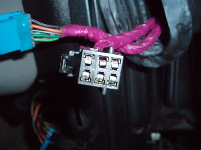
If you find any deformed pins, use a metal pick and bend the deformed tong back up so that it makes better connection.
See how that works.
BC
Pop the rubber tubes out on BOTH doors and carefully inspect the female pins in ALL the door connections. Pull the connectors out of the door frame A pillar.
IF,,, ANY of the pins look like the one in the top row center pin,, thats most likely your poor connection
If you find any deformed pins, use a metal pick and bend the deformed tong back up so that it makes better connection.
See how that works.
BC
Corvette Stories
The Best of Corvette for Corvette Enthusiasts

Top 10 Most Expensive Corvettes Ever Sold on Bring A Trailer
Brett Foote
10 Things Every Corvette Owner Needs (2026 Edition)
Michael S. Palmer
8 Most "Only Corvette Owners Understand" Quirks and Problems
Pouria Savadkouei
10 Reasons the C6 Z06 is Still A Performance Benchmark After 20 Years
Joe Kucinski
How Much Horsepower Every Corvette Engine "LOST" in 1972
Joe Kucinski
Top 10 DOs and DON'Ts for Protecting Your Convertible Top!
Michael S. Palmer
Top 10 Most Explosive Corvettes Ever Made: Power-to-Weight Ratio Ranked!
Joe Kucinski
150 hp to 1,250 hp: Every Corvette Generation Compared by the Specs That Matter
Joe Kucinski
8 Coolest Corvette Pace Cars (and Replicas) of All Time
Verdad GallardoRace Director
Joined: May 2005
Posts: 15,960
Likes: 21
From: West Norriton PA
St. Jude Donor '08
Would also check out the wiring by the battery since you stated that you have some corosion caused by a leaked battery.
Also check that your cables are tight to the battery, starter and fuse box.
Also check that your cables are tight to the battery, starter and fuse box.
Thread Starter
Instructor
Joined: Aug 2009
Posts: 218
Likes: 5
From: OR
Thanks Bill.
Back in May I did pull each one out of the accordian on each door and seal the back sides with liquid tape. I did not look closely at the male and female plug ends, but you can bet your sweet cheeks I'll do it now!
J.H.
Back in May I did pull each one out of the accordian on each door and seal the back sides with liquid tape. I did not look closely at the male and female plug ends, but you can bet your sweet cheeks I'll do it now!
J.H.
Thread Starter
Instructor
Joined: Aug 2009
Posts: 218
Likes: 5
From: OR
Finally had a chance to get back at this.
I pulled the accordian tubes on both doors and inspected all connectors - all is good.
It is to the point now that it throws a code or two just driving it a block or so and the farther you drive it, the number or warnings and lights increases until it eventually lights up all the warning lights and then acts and looks like the ignition switch is in the on position without the engine running. Then, after you park, shut the engine off and remove the key, the DIC dings and displays some or all of the nastygrams in a random order (shocks inop, reduced power, service vehicle soon, check tire pressure, etc, etc).
I just checked it after clearing the DIC and then driving it until the 1st msg appeared - about 2 blocks.
Here's what I got pulling over as soon as msg appears, the car is in park and idling.
38 RTD - NO COMM
60 IPC - U1056 H C
Is the ignition switch a possibilty?
Thread Starter
Instructor
Joined: Aug 2009
Posts: 218
Likes: 5
From: OR
Turned out to be a bad shock at the right rear. I would tell the story but it would take too long to type and I'd end up with calluses on my finger tips. Anyway, once I knew that I was on the right track I swapped the shock with one that was used but known to be good - problem went away. Then I replaced all 4 with Bilsteins and did the Radio Shack resistor fix.
Problem and shame no mo'.
Problem and shame no mo'.