


P0132C and P0300C after header install
Thread Starter
Instructor

Joined: Jul 2009
Posts: 241
Likes: 1
From: Richmond Va
I have exhausted all my knowledge on this and looking for a helping hand. On my 98' I installed a set of dynatech LT, w/high flow cats and plugs and wires(AC delco OEM stuff). I'm running all four O2's as the fronts have extensions and the rears are plugged in original locations left to right and right to left. Front's are right to right left to left(Triple checked). Car idles find then stumbles and buckles once warm, and then takes off and drives find for a while. Car is running very rich and i thought it would smooth out a little I was wrong . Anyway double checked plugs and wires for loose and cracks(nothing), checked driver side front 02 for burned wire(nothing). Also checked mini fuse 15 under hood and it was not blown. I know front 02's in open loop do not adjust fuel thats why it idles fine until they are put into closed loop car runs like crap! I hate to throw parts at it but seems like a fried front driver 02 which is telling PCM to dump fuel(p0132C) and soaked the driver side plugs(0300C) mis-fire or could i have a leaky injector as i removed the fuel rails to remove valve cover and coil packs. Any help would be greatly appreciated as I am worn out!
. Anyway double checked plugs and wires for loose and cracks(nothing), checked driver side front 02 for burned wire(nothing). Also checked mini fuse 15 under hood and it was not blown. I know front 02's in open loop do not adjust fuel thats why it idles fine until they are put into closed loop car runs like crap! I hate to throw parts at it but seems like a fried front driver 02 which is telling PCM to dump fuel(p0132C) and soaked the driver side plugs(0300C) mis-fire or could i have a leaky injector as i removed the fuel rails to remove valve cover and coil packs. Any help would be greatly appreciated as I am worn out!

Le Mans Master


Joined: Jun 2008
Posts: 5,284
Likes: 235
From: Rockledge FL
0300 just has to be a wire or a plug at this point. if it was running fine before the headers then there has to be a loose plug wire, or a cracked plug. when you put the 02 sensors back in did you maybe get some anti-sieze on them?
Thread Starter
Instructor
Joined: Jul 2009
Posts: 241
Likes: 1
From: Richmond Va
Thanks for response , since i dont have equipment to pin point mis fire my take another look at plugs and wires to take care of the P0300. If I cure P0300, will p0132 make the car stumble and buckle or jus run rich until I can replace front O2?
, since i dont have equipment to pin point mis fire my take another look at plugs and wires to take care of the P0300. If I cure P0300, will p0132 make the car stumble and buckle or jus run rich until I can replace front O2?
Racer


Joined: Mar 2003
Posts: 440
Likes: 7
From: Willow Park Texas
If you are reading P0300 on the DIC, you need to get another scanner. The onboard scanner in a C5 returns P0300 for every code from P0300 to P0308. Another scanner will tell you which cylinder is actually missing.
Reb
Reb
Tech Contributor

Joined: Dec 2006
Posts: 10,962
Likes: 29
From: Van Buren Arkansas
Wounded Warrior Escort '11
Usually when I hear the P0300 code, random misfire, its usually the ground wire on the rear of the driver's side head, has come lose. The other usual suspects are reversing the O2 sensor wires with the wrong sides.

Tech Contributor


Joined: Dec 1999
Posts: 32,910
Likes: 2,402
From: Anthony TX
CI 6,7,8,9,11 Vet
St. Jude Donor '08
How are youchecking the wires and plugs???
Did you remobe ALL the plugs for the header install. If not,, this is what usually happens. Some crack where you cant easily see them.:
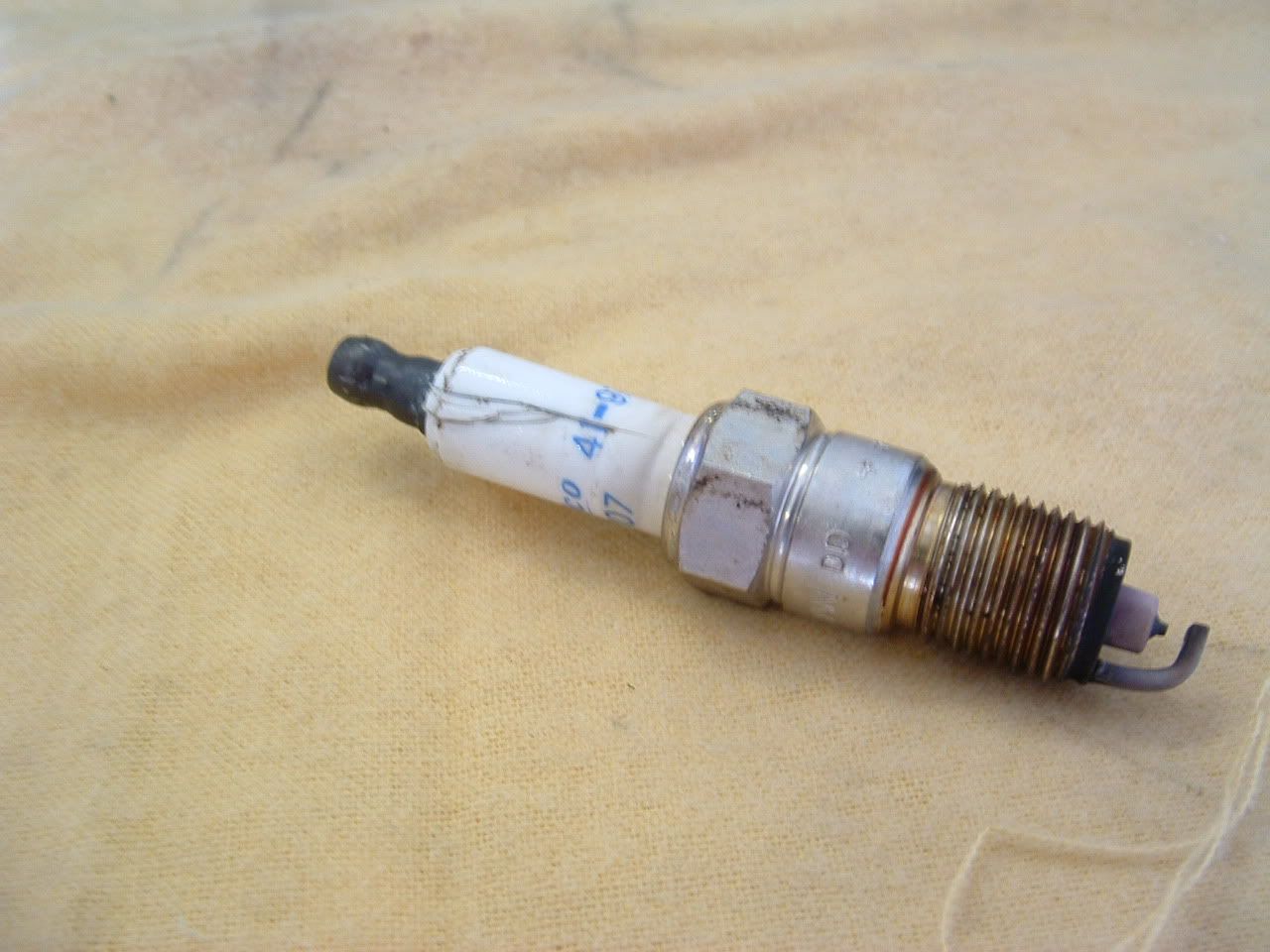
Each wire is a spiral wound core and if the core is broken, the wire can cause a misfire.
Stock wires are normaly 300-400 ohms Spec 275-750 ohms/
Make sure that the coil and plug boots are properly snapped on. It does make a difference if there only partially connected.
Yes,, the misfire will cause weird O2 sensor readings.
If the
DTC P0132 HO2S Circuit High Voltage Bank 1 Sensor 1
Circuit Description
The powertrain control module (PCM) supplies a voltage of about 450 mV between the HO2S high and low signal circuits. The oxygen sensor varies the voltage over a range from about 1,000 mV when the exhaust is rich, down through about 10 mV when the exhaust is lean.
The PCM monitors and stores the heated oxygen sensor (HO2S) voltage information. The PCM evaluates the HO2S voltage samples in order to determine the amount of time the HO2S voltage was out of range. The PCM compares the stored HO2S voltage samples taken within each sample period and determines if majority of the samples are out of the operating range.
The PCM monitors the HO2S voltage for being fixed above a predetermined voltage. If the PCM detects the voltage is above a predetermined voltage, a DTC sets.
Conditions for Running the DTC
DTCs P0101, P0102, P0103, P0112, P0113, P0117, P0118, P0125, P0200, P0335, P0336, P0351-P0358, P1120, P1220, P1221, P1258 are not set.
The ignition voltage is more than 9.0 volts.
The fuel system is operating in Closed Loop.
The AIR and the catalyst diagnostics are not active.
The throttle position (TP) angle is between 2 percent and 70 percent.
Conditions for Setting the DTC
The HO2S signal voltage remains above 775 mV.
The conditions are present for 33 seconds.
Action Taken When the DTC Sets
The PCM illuminates the malfunction indicator lamp (MIL) on the second consecutive ignition cycle that the diagnostic runs and fails.
The PCM records the operating conditions at the time the diagnostic fails. The first time the diagnostic fails, the PCM stores this information in the Failure Records. If the diagnostic reports a failure on the second consecutive ignition cycle, the PCM records the operating conditions at the time of the failure. The PCM writes the conditions to the Freeze Frame and updates the Failure Records.
Conditions for Clearing the MIL/DTC
The PCM turns OFF the malfunction indicator lamp (MIL) after 3 consecutive ignition cycles that the diagnostic runs and does not fail.
A last test failed, or current DTC, clears when the diagnostic runs and does not fail.
A history DTC clears after 40 consecutive warm-up cycles, if no failures are reported by this or any other emission related diagnostic.
Use a scan tool in order to clear the MIL and the DTC.
Diagnostic Aids
Important
Remove any debris from the PCM\TAC module connector surfaces before servicing the PCM\TAC module. Inspect the PCM\TAC module connector gaskets when diagnosing/replacing the modules. Ensure that the gaskets are installed correctly. The gaskets prevent contaminate intrusion into the PCM\TAC modules.
For any test that requires probing the PCM or a component harness connector, use the Connector Test Adapter Kit J 35616-A . Using this kit prevents damage to the harness/component terminals. Refer to Using Connector Test Adapters in Wiring Systems.
Inspect the HO2S electrical connections for evidence of water intrusion--Water present in the connector causes the B+ supply to the heater to bleed over to the signal circuit.
Fuel pressure--The system goes rich if the pressure is too high. The PCM compensates for some increase. However, if the fuel pressure is too high, a DTC may set. Refer to Fuel System Diagnosis .
Rich injectors--Perform the Injector Balance Test. Refer to Fuel Injector Balance Test with Tech 2 or Fuel Injector Balance Test with Special Tool .
Leaking injector--Refer to the Fuel System Diagnosis .
Evaporative emissions (EVAP) canister purge--Inspect for fuel saturation. If full of fuel, inspect the canister control and hoses. Refer to Evaporative Emission (EVAP) Control System Operation Description .
MAF sensor--Disconnect the MAF sensor and see if the rich condition is corrected. If so, inspect for proper installation. If installed correctly, replace the MAF sensor. If the MAF sensor is installed backwards, the system goes rich. The plastic portion of the sensor has arrows indicating proper air flow direction. The arrows must point towards the engine.
An oxygen supply inside the HO2S is necessary for proper operation. The HO2S wires provide the supply of oxygen. Inspect the HO2S wires and connections for breaks or contamination. Refer to Wiring Repairs in Wiring Systems.
For an intermittent condition, refer to Symptoms .
Test Description
The numbers below refer to the step numbers on the diagnostic table.
This step is testing for a rich condition.
The engine must be at the normal operating temperature before performing this test.
Using the Freeze Frame and/or Failure Records data may aid in locating an intermittent condition. If you can not duplicate the DTC, the information included in the Freeze Frame and/or Failure Records data can help determine how many miles since the DTC set. The Fail Counter and Pass Counter can also aid in determining how many ignition cycles the diagnostic reported a pass and/or a fail. Operate the vehicle within the same freeze frame conditions (RPM, load, vehicle speed, temperature , etc.) that the PCM recorded. This isolates when the DTC failed.
If the voltage remains high, this indicates the signal circuit is shorted to a voltage. If the voltage goes low, this indicates a rich condition.
This step isolates the condition. If the voltage remains high, this indicates the signal circuit is not shorted to the heater feed circuit.
Test for a short to voltage between the HO2S signal circuit and any other wires powered by the HO2S fuse.
Step
Action
Values
Yes
No
1
Did you perform the Powertrain On-Board Diagnostic (OBD) System Check?
--
Go to Step 2
Go to Powertrain On Board Diagnostic (OBD) System Check
2
Install a scan tool.
Start the engine and idle at the normal operating temperature.
Operate the engine above 1200 RPM for two minutes.
Monitor the HO2S voltage display on the Engine 1 Data List using a scan tool.
Is the HO2S voltage greater than the specified value?
775 mV
Go to Step 4
Go to Step 3
3
Turn ON the ignition leaving the engine OFF.
Review the Freeze Frame and/or Failure Records data for this DTC and observe the parameters.
Turn OFF the ignition for 15 seconds.
Start the engine.
Operate the vehicle within the conditions required for this diagnostic to run, and as close to the conditions recorded in the Freeze Frame/Failure Records as possible. Special operating conditions that you need to meet before the PCM will run this diagnostic, where applicable, are listed in Conditions for Running the DTC.
Select the Diagnostic Trouble Code (DTC) option, the Specific DTC option, and then enter the DTC number using the scan tool.
Does the scan tool indicate that this diagnostic failed this ignition?
--
Go to Step 4
Go to Diagnostic Aids
4
Turn ON the ignition leaving the engine OFF.
Monitor the HO2S voltage using a scan tool.
Is the HO2S voltage greater than the specified value?
775 mV
Go to Step 5
Go to Diagnostic Aids
5
Remove the HO2S heater fuse while monitoring the HO2S voltage.
Does the voltage drop to within the specified range when the power to the heater is disconnected?
350-550 mV
Go to Step 6
Go to Step 7
6
Reinstall the fuse.
Disconnect the HO2S.
Jumper the HO2S low circuit (PCM side) to a known good ground.
Monitor the HO2S voltage using the scan tool.
Does the scan tool indicate the HO2S voltage within the specified range?
350-550 mV
Go to Step 10
Go to Step 8
7
Important
Disconnecting the PCM may eliminate the short to voltage if the signal circuit is shorted to another C1 circuit.
Turn OFF the ignition.
Disconnect the PCM connector C1 located on the same side as the manufacturer's logo. Refer to Powertrain Control Module (PCM) Replacement .
Disconnect the HO2S.
Turn ON the ignition leaving the engine OFF.
Test for a voltage on the HO2S sensor signal circuit at the PCM harness connector using the DMM J 39200 .
Is a voltage present?
--
Go to Step 8
Go to Step 9
8
Repair the short to voltage in the HO2S signal circuit. Refer to Wiring Repairs in Wiring Systems.
Is the action complete?
--
Go to Step 11
--
9
Important
Program the replacement PCM.
Replace the PCM. Refer to Powertrain Control Module (PCM) Replacement .
Is the action complete?
--
Go to Step 11
--
10
Replace the HO2S. Refer to Heated Oxygen Sensor (HO2S) Replacement Bank 1 Sensor 1 .
Is the action complete?
--
Go to Step 11
--
11
Select the Diagnostic Trouble Code (DTC) option and the Clear DTC Information option using the scan tool.
Start the engine and idle at the normal operating temperature.
Select the Diagnostic Trouble Code (DTC) option and the Specific DTC option, then enter the DTC number using the scan tool.
Operate the vehicle within the Conditions for Running the DTC as specified in the supporting text, if applicable.
Does the scan tool indicate that this test ran and passed?
--
Go to Step 12
Go to Step 2
12
Select the Capture Info option and the Review Info option using the scan tool.
Does the scan tool display any DTCs that you have not diagnosed?
--
Go to the applicable DTC table
System OK
--------------------------------------------------------------------------------
Document ID# 554093
2000 Chevrolet/Geo Corvette
If it were ME,,, I would look for O2 sensor wiring damage/ connector damage etc...
BC
Did you remobe ALL the plugs for the header install. If not,, this is what usually happens. Some crack where you cant easily see them.:
Each wire is a spiral wound core and if the core is broken, the wire can cause a misfire.
Stock wires are normaly 300-400 ohms Spec 275-750 ohms/
Make sure that the coil and plug boots are properly snapped on. It does make a difference if there only partially connected.
Yes,, the misfire will cause weird O2 sensor readings.
If the
DTC P0132 HO2S Circuit High Voltage Bank 1 Sensor 1
Circuit Description
The powertrain control module (PCM) supplies a voltage of about 450 mV between the HO2S high and low signal circuits. The oxygen sensor varies the voltage over a range from about 1,000 mV when the exhaust is rich, down through about 10 mV when the exhaust is lean.
The PCM monitors and stores the heated oxygen sensor (HO2S) voltage information. The PCM evaluates the HO2S voltage samples in order to determine the amount of time the HO2S voltage was out of range. The PCM compares the stored HO2S voltage samples taken within each sample period and determines if majority of the samples are out of the operating range.
The PCM monitors the HO2S voltage for being fixed above a predetermined voltage. If the PCM detects the voltage is above a predetermined voltage, a DTC sets.
Conditions for Running the DTC
DTCs P0101, P0102, P0103, P0112, P0113, P0117, P0118, P0125, P0200, P0335, P0336, P0351-P0358, P1120, P1220, P1221, P1258 are not set.
The ignition voltage is more than 9.0 volts.
The fuel system is operating in Closed Loop.
The AIR and the catalyst diagnostics are not active.
The throttle position (TP) angle is between 2 percent and 70 percent.
Conditions for Setting the DTC
The HO2S signal voltage remains above 775 mV.
The conditions are present for 33 seconds.
Action Taken When the DTC Sets
The PCM illuminates the malfunction indicator lamp (MIL) on the second consecutive ignition cycle that the diagnostic runs and fails.
The PCM records the operating conditions at the time the diagnostic fails. The first time the diagnostic fails, the PCM stores this information in the Failure Records. If the diagnostic reports a failure on the second consecutive ignition cycle, the PCM records the operating conditions at the time of the failure. The PCM writes the conditions to the Freeze Frame and updates the Failure Records.
Conditions for Clearing the MIL/DTC
The PCM turns OFF the malfunction indicator lamp (MIL) after 3 consecutive ignition cycles that the diagnostic runs and does not fail.
A last test failed, or current DTC, clears when the diagnostic runs and does not fail.
A history DTC clears after 40 consecutive warm-up cycles, if no failures are reported by this or any other emission related diagnostic.
Use a scan tool in order to clear the MIL and the DTC.
Diagnostic Aids
Important
Remove any debris from the PCM\TAC module connector surfaces before servicing the PCM\TAC module. Inspect the PCM\TAC module connector gaskets when diagnosing/replacing the modules. Ensure that the gaskets are installed correctly. The gaskets prevent contaminate intrusion into the PCM\TAC modules.
For any test that requires probing the PCM or a component harness connector, use the Connector Test Adapter Kit J 35616-A . Using this kit prevents damage to the harness/component terminals. Refer to Using Connector Test Adapters in Wiring Systems.
Inspect the HO2S electrical connections for evidence of water intrusion--Water present in the connector causes the B+ supply to the heater to bleed over to the signal circuit.
Fuel pressure--The system goes rich if the pressure is too high. The PCM compensates for some increase. However, if the fuel pressure is too high, a DTC may set. Refer to Fuel System Diagnosis .
Rich injectors--Perform the Injector Balance Test. Refer to Fuel Injector Balance Test with Tech 2 or Fuel Injector Balance Test with Special Tool .
Leaking injector--Refer to the Fuel System Diagnosis .
Evaporative emissions (EVAP) canister purge--Inspect for fuel saturation. If full of fuel, inspect the canister control and hoses. Refer to Evaporative Emission (EVAP) Control System Operation Description .
MAF sensor--Disconnect the MAF sensor and see if the rich condition is corrected. If so, inspect for proper installation. If installed correctly, replace the MAF sensor. If the MAF sensor is installed backwards, the system goes rich. The plastic portion of the sensor has arrows indicating proper air flow direction. The arrows must point towards the engine.
An oxygen supply inside the HO2S is necessary for proper operation. The HO2S wires provide the supply of oxygen. Inspect the HO2S wires and connections for breaks or contamination. Refer to Wiring Repairs in Wiring Systems.
For an intermittent condition, refer to Symptoms .
Test Description
The numbers below refer to the step numbers on the diagnostic table.
This step is testing for a rich condition.
The engine must be at the normal operating temperature before performing this test.
Using the Freeze Frame and/or Failure Records data may aid in locating an intermittent condition. If you can not duplicate the DTC, the information included in the Freeze Frame and/or Failure Records data can help determine how many miles since the DTC set. The Fail Counter and Pass Counter can also aid in determining how many ignition cycles the diagnostic reported a pass and/or a fail. Operate the vehicle within the same freeze frame conditions (RPM, load, vehicle speed, temperature , etc.) that the PCM recorded. This isolates when the DTC failed.
If the voltage remains high, this indicates the signal circuit is shorted to a voltage. If the voltage goes low, this indicates a rich condition.
This step isolates the condition. If the voltage remains high, this indicates the signal circuit is not shorted to the heater feed circuit.
Test for a short to voltage between the HO2S signal circuit and any other wires powered by the HO2S fuse.
Step
Action
Values
Yes
No
1
Did you perform the Powertrain On-Board Diagnostic (OBD) System Check?
--
Go to Step 2
Go to Powertrain On Board Diagnostic (OBD) System Check
2
Install a scan tool.
Start the engine and idle at the normal operating temperature.
Operate the engine above 1200 RPM for two minutes.
Monitor the HO2S voltage display on the Engine 1 Data List using a scan tool.
Is the HO2S voltage greater than the specified value?
775 mV
Go to Step 4
Go to Step 3
3
Turn ON the ignition leaving the engine OFF.
Review the Freeze Frame and/or Failure Records data for this DTC and observe the parameters.
Turn OFF the ignition for 15 seconds.
Start the engine.
Operate the vehicle within the conditions required for this diagnostic to run, and as close to the conditions recorded in the Freeze Frame/Failure Records as possible. Special operating conditions that you need to meet before the PCM will run this diagnostic, where applicable, are listed in Conditions for Running the DTC.
Select the Diagnostic Trouble Code (DTC) option, the Specific DTC option, and then enter the DTC number using the scan tool.
Does the scan tool indicate that this diagnostic failed this ignition?
--
Go to Step 4
Go to Diagnostic Aids
4
Turn ON the ignition leaving the engine OFF.
Monitor the HO2S voltage using a scan tool.
Is the HO2S voltage greater than the specified value?
775 mV
Go to Step 5
Go to Diagnostic Aids
5
Remove the HO2S heater fuse while monitoring the HO2S voltage.
Does the voltage drop to within the specified range when the power to the heater is disconnected?
350-550 mV
Go to Step 6
Go to Step 7
6
Reinstall the fuse.
Disconnect the HO2S.
Jumper the HO2S low circuit (PCM side) to a known good ground.
Monitor the HO2S voltage using the scan tool.
Does the scan tool indicate the HO2S voltage within the specified range?
350-550 mV
Go to Step 10
Go to Step 8
7
Important
Disconnecting the PCM may eliminate the short to voltage if the signal circuit is shorted to another C1 circuit.
Turn OFF the ignition.
Disconnect the PCM connector C1 located on the same side as the manufacturer's logo. Refer to Powertrain Control Module (PCM) Replacement .
Disconnect the HO2S.
Turn ON the ignition leaving the engine OFF.
Test for a voltage on the HO2S sensor signal circuit at the PCM harness connector using the DMM J 39200 .
Is a voltage present?
--
Go to Step 8
Go to Step 9
8
Repair the short to voltage in the HO2S signal circuit. Refer to Wiring Repairs in Wiring Systems.
Is the action complete?
--
Go to Step 11
--
9
Important
Program the replacement PCM.
Replace the PCM. Refer to Powertrain Control Module (PCM) Replacement .
Is the action complete?
--
Go to Step 11
--
10
Replace the HO2S. Refer to Heated Oxygen Sensor (HO2S) Replacement Bank 1 Sensor 1 .
Is the action complete?
--
Go to Step 11
--
11
Select the Diagnostic Trouble Code (DTC) option and the Clear DTC Information option using the scan tool.
Start the engine and idle at the normal operating temperature.
Select the Diagnostic Trouble Code (DTC) option and the Specific DTC option, then enter the DTC number using the scan tool.
Operate the vehicle within the Conditions for Running the DTC as specified in the supporting text, if applicable.
Does the scan tool indicate that this test ran and passed?
--
Go to Step 12
Go to Step 2
12
Select the Capture Info option and the Review Info option using the scan tool.
Does the scan tool display any DTCs that you have not diagnosed?
--
Go to the applicable DTC table
System OK
--------------------------------------------------------------------------------
Document ID# 554093
2000 Chevrolet/Geo Corvette
If it were ME,,, I would look for O2 sensor wiring damage/ connector damage etc...
BC
Corvette Stories
The Best of Corvette for Corvette Enthusiasts

5 Best & 5 Worst Corvette Daily Drivers
Joe Kucinski
The Headlights of Every Corvette Generation Explained
Joe Kucinski
5 Best & 5 Most Overrated Corvette Track Packages of All Time!
Joe Kucinski
Every 2027 Corvette Engine Explained
Joe Kucinski
Designer Imagines A Corvette That Looks More Like a Corvette Than the Corvette
Verdad Gallardo
10 Ugly Corvettes That We Still Kinda Love
Joe Kucinski
Top 10 Most Expensive Corvettes Ever Sold on Bring A Trailer
Brett Foote
10 Things Every Corvette Owner Needs (2026 Edition)
Michael S. Palmer
8 Most "Only Corvette Owners Understand" Quirks and Problems
Pouria Savadkouei
Thread Starter
Instructor
Joined: Jul 2009
Posts: 241
Likes: 1
From: Richmond Va
Well after further inspection, I have to swallow my pride and admit I've committed the most common mistake of a header install, crossing the front o2 sensors I guess triple checking just wasn't enough. Thanks to all who replied and answered PM's. "the more mistakes I make the smarter I get".
.