


 That would be my first guess.


2002 Corvette will not start

Thread Starter
6th Gear

Joined: Feb 2012
Posts: 6
Likes: 0
It is a 2002 with an automatic transmission. I am finding the following 3 codes.
B2587H Column Lock/Unlock Drive (A)
B2592H Column Lock/Unlock Drive ( B )
B2264H Vertical Position Sensor Fault
I have tested the battery and checked all the fuses and relays and they are fine. I'm not getting any messages to pull the key and wait 10 seconds or anything about column lock. From what I can tell, this shouldn't have a column lock since it is a 2002.
When I attempt to start it all of the gauges drop to zero and the interior lights turn off. I can hear the fuel pump turn on when I turn the key to run. I'm fairly mechanical and good at working on cars/wiring. Any help on where to look would be great!
Car specs:
2002 Automatic
Mileage: 70k
Mostly garage kept and driven about 4-5 times a week
No modifications done to it at all
Thread Starter
6th Gear
Joined: Feb 2012
Posts: 6
Likes: 0
Floor jack I have is too tall to get underneath it to jack it up. The engine won't crank at all. Those are the only 3 codes I have seen when I hold down option and press fuel 4 times. Is there another way to check for any more codes.
The battery was load tested and tested as good.
The battery was load tested and tested as good.

Le Mans Master

Joined: Nov 2005
Posts: 6,993
Likes: 25
Floor jack I have is too tall to get underneath it to jack it up. The engine won't crank at all. Those are the only 3 codes I have seen when I hold down option and press fuel 4 times. Is there another way to check for any more codes.
The battery was load tested and tested as good.
The battery was load tested and tested as good.

Tech Contributor


Joined: Dec 1999
Posts: 32,910
Likes: 2,402
From: Anthony TX
CI 6,7,8,9,11 Vet
St. Jude Donor '08
From the gm service guide,, here ya go
DTC B2262 Horizontal Position Sensor Circuit. This isnt you Column Lock Issue but,, Im giving you the definition so you can eliminate it.
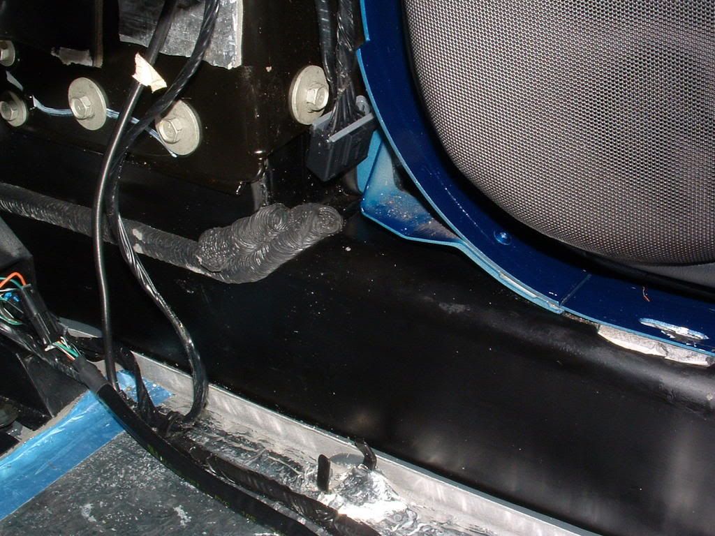
You either have a BCM issue or a Column Lock motor issue. Check the column lock relay and BCM2 FUSE
Grounds G-201 7202 are very important also. There under the door sill cover on either side:
Circuit Description
The LH Door Control Module (LDCM) receives a horizontal position signal from the LH mirror horizontal position sensor. This signal is used by the LDCM for memory recall functions to determine the horizontal position of the LH mirror. The LDCM commands the mirror memory settings based upon the voltage level the LDCM receives back from the horizontal position sensor. The LDCM provides a 5 volt supply (CKT 788), a signal (CKT 786) and a ground (CKT 1251) to the horizontal position sensor. The horizontal position sensor is a variable resistor which the LDCM monitors the voltage level across. When a memory setting is recalled, the LDCM will command the LH mirror motor in the appropriate direction until the stored position sensor voltage level is achieved. The LDCM also monitors the LH mirror horizontal position signal circuit and can determine if the voltage level received is out of range. If the voltage level is out of range, then a malfunction is present and a DTC will set.
Conditions for Setting the DTC
The LDCM detects LH mirror horizontal position sensor signal voltage range under 0.1 volts or over 4.78 volts.
Condition must be present for 2 seconds.
Action Taken When the DTC Sets
Stores a history DTC B2262 in the LDCM memory.
This DTC can only be set as a history code even if the malfunction is current.
No driver warning message will be displayed for this DTC.
Conditions for Clearing the DTC
The LDCM detects the correct LH mirror horizontal position sensor signal voltage range (0.1-4.78 volts) for longer than 2 seconds.
Use the IPC clearing DTCs feature.
Use a scan tool.
Diagnostic Aids
The following conditions may cause an intermittent malfunction:
There is an intermittent open or short (to ground or voltage) in CKT 1251, CKT 786, or CKT 788.
The LH mirror horizontal position sensor is open or shorted internally.
If the LDCM is unable to determine the correct horizontal position, manual power mirror functions will still operate, but the LDCM will not be able to recall the correct mirror memory settings.
Using a scan tool, select LDCM Data display and monitor the mirror horizontal position data. Move the LH power mirror horizontally in both direction while monitoring the horizontal position sensor data. The voltage range should vary and stay between 0.1-4.78 volts depending on the direction of the mirror. This checks if the mirror horizontal position sensor is open or shorted in different positions.
If the DTC does not reset after the code is cleared, then the problem may be intermittent. Perform the tests shown while moving related wiring and connectors. This can often cause the malfunction to occur. Refer to Intermittents and Poor Connections .
Test Description
The numbers below refer to the step numbers on the diagnostic table:
This test checks if a DTC B2264 stored in the LDCM memory.
This test checks the mirror horizontal position sensor voltage using a scan tool. Normal mirror horizontal position sensor voltage range is between 0.1-4.78 volts.
This test checks if the LDCM is sending the correct supply voltage to the LH mirror. The supply voltage measured must be between 4.0-5.5 volts.
This test checks for an open or short to voltage in CKT 1251 or in the LDCM internal ground circuit.
This test checks the output voltage level at the LH mirror horizontal position sensor signal circuit. The signal voltage measured must be between 3.5-5.5 volts.
DTC B2262 Step
Action
Value(s)
Yes
No
1
Were you sent here from the Power Door Diagnostic System Check?
--
Go to Step 2
Go to Diagnostic System Check - Power Door Systems
2
Using a scan tool, select LDCM DTC display and check for a DTC B2264.
Is DTC B2264 stored as history?
--
Go to Step 3
Go to Step 6
3
Using a scan tool, select LDCM data display and monitor the mirror horizontal position sensor data while operating the LH mirror.
Does the scan tool display mirror horizontal position sensor voltage within the specified range?
0.1-4.78 V
Go to Step 12
Go to Step 4
4
Turn OFF the ignition switch.
Disconnect the LH mirror connector C2.
Turn ON the ignition switch.
At the LH mirror connector C2 (harness side), measure the voltage between terminal A and ground while operating the LH mirror.
Is the voltage within the specified range?
4.0-5.5 V
Go to Step 5
Go to Step 7
5
At the LH mirror connector C2 (harness side), measure the voltage between terminals A and C while operating the LH mirror.
Is the voltage within the specified range?
4.0-5.5 V
Go to Step 10
Go to Step 8
6
Turn OFF the ignition switch.
Disconnect the LH mirror connector C2.
Turn ON the ignition switch.
At the LH mirror connector C2 (harness side), measure the voltage between terminal D and ground while operating the LH mirror.
Is the voltage within the specified range?
3.5-5.5 V
Go to Step 10
Go to Step 9
7
Check for an open or short (to ground or voltage) in CKT 788.
Was a problem found and repaired?
--
Go to Step 14
Go to Step 11
8
Check for an open or short to voltage in CKT 1251.
Was a problem found and repaired?
--
Go to Step 14
Go to Step 11
9
Check for an open or short (to ground or voltage) in CKT 786.
Was a problem found and repaired?
--
Go to Step 14
Go to Step 11
10
Replace the LH mirror assembly. Refer to Mirror Replacement .
Is the replacement complete?
--
Go to Step 14
--
11
Replace the LDCM. Refer to Door Control Module Replacement .
Is the replacement complete?
--
Go to Step 14
--
12
Check the mirror horizontal position sensor circuit for an intermittent malfunction. Refer to Diagnostic Aids.
Was a problem found and repaired?
--
Go to Step 14
Go to Step 13
13
Turn OFF the ignition switch.
Reconnect or install any connectors or components that were disconnected or removed.
Turn ON the ignition switch.
Clear any DTCs. Refer to Diagnostic Trouble Code (DTC) Clearing .
Wait 2 seconds.
Does DTC B2262 set as history?
--
Go to Step 11
System OK
14
Turn OFF the ignition switch.
Reconnect or install any connectors or components that were disconnected or removed.
Turn ON the ignition switch.
Clear any DTCs. Refer to Diagnostic Trouble Code (DTC) Clearing .
Is the repair complete?
--
Go to Diagnostic System Check - Power Door Systems
--
DTC B2264 Vertical Position Sensor Circuit
Circuit Description
The LH Door Control Module (LDCM) receives a vertical position signal from the LH mirror vertical position sensor. This signal is used by the LDCM for memory recall functions to determine the vertical position of the LH mirror. The LDCM commands the mirror memory settings based upon the voltage level the LDCM receives back from the vertical position sensor. The LDCM provides a 5 volt supply (CKT 788), a signal (CKT 784) and a ground (CKT 1251) to the vertical position sensor. The vertical position sensor is a variable resistor which the LDCM monitors the voltage level across. When a memory setting is recalled, the LDCM will command the LH mirror motor in the appropriate direction until the stored position sensor voltage level is achieved. The LDCM also monitors the LH mirror vertical position signal circuit and can determine if the voltage level received is out of range. If the voltage level is out of range, then a malfunction is present and a DTC will set.
Conditions for Setting the DTC
The LDCM detects LH mirror vertical position sensor signal voltage range under 0.1 volts or over 4.78 volts.
Condition must be present for 2 seconds.
Action Taken When the DTC Sets
Stores a history DTC B2264 in the LDCM memory.
This DTC can only be set as a history code even if the malfunction is current.
No driver warning message will be displayed for this DTC.
Conditions for Clearing the DTC
The LDCM detects the correct LH mirror vertical position sensor signal voltage range (0.1-4.78 volts) for longer than 2 seconds.
Use the IPC clearing DTCs feature.
Use a scan tool.
Diagnostic Aids
The following conditions may cause an intermittent malfunction:
There is an intermittent open or short (to ground or voltage) in CKT 1251, CKT 784, or CKT 788.
The LH mirror vertical position sensor is open or shorted internally.
If the LDCM is unable to determine the correct vertical position, manual power mirror functions will still operate, but the LDCM will not be able to recall the correct mirror memory settings.
Using a scan tool, select LDCM Data display and monitor the mirror vertical position data. Move the LH power mirror vertically in both direction while monitoring the vertical position sensor data. The voltage range should vary and stay between 0.1-4.78 volts depending on the direction of the mirror. This checks if the mirror vertical position sensor is open or shorted in different positions.
If the DTC does not reset after the code is cleared, then the problem may be intermittent. Perform the tests shown while moving related wiring and connectors. This can often cause the malfunction to occur. Refer to Intermittents and Poor Connections .
Test Description
The numbers below refer to the step numbers on the diagnostic table:
This test checks if a DTC B2262 stored in the LDCM memory.
This test checks the mirror vertical position sensor voltage using a scan tool. Normal mirror vertical position sensor voltage range is between 0.1-4.78 volts.
This test checks if the LDCM is sending the correct supply voltage to the LH mirror. The supply voltage measured must be between 4.0-5.5 volts.
This test checks for an open or short to voltage in CKT 1251 or in the LDCM internal ground circuit.
This test checks the output voltage level at the LH mirror vertical position sensor signal circuit. The signal voltage measured must be between 3.5-5.5 volts.
DTC B2264 Step
Action
Value(s)
Yes
No
1
Were you sent here from the Power Door Diagnostic System Check?
--
Go to Step 2
Go to Diagnostic System Check - Power Door Systems
2
Using a scan tool, select LDCM DTC display and check for a DTC B2262.
Is DTC B2262 stored as history?
--
Go to Step 3
Go to Step 6
3
Using a scan tool, select LDCM data display and monitor the mirror vertical position sensor data while operating the LH mirror.
Does the scan tool display mirror vertical position sensor voltage within the specified range?
0.1-4.78 V
Go to Step 12
Go to Step 4
4
Turn OFF the ignition switch.
Disconnect the LH mirror connector C2.
Turn ON the ignition switch.
At the LH mirror connector C2 (harness side), measure the voltage between terminal A and ground while operating the LH mirror.
Is the voltage within the specified range?
4.0-5.5 V
Go to Step 5
Go to Step 7
5
At the LH mirror connector C2 (harness side), measure the voltage between terminals A and C while operating the LH mirror.
Is the voltage within the specified range?
4.0-5.5 V
Go to Step 10
Go to Step 8
6
Turn OFF the ignition switch.
Disconnect the LH mirror connector C2.
Turn ON the ignition switch.
At the LH mirror connector C2 (harness side), measure the voltage between terminal D and ground while operating the LH mirror.
Is the voltage within the specified range?
3.5-5.5 V
Go to Step 10
Go to Step 9
7
Check for an open or short (to ground or voltage) in CKT 788.
Was a problem found and repaired?
--
Go to Step 14
Go to Step 11
8
Check for an open or short to voltage in CKT 1251.
Was a problem found and repaired?
--
Go to Step 14
Go to Step 11
9
Check for an open or short (to ground or voltage) in CKT 784.
Was a problem found and repaired?
--
Go to Step 14
Go to Step 11
10
Replace the LH mirror assembly. Refer to Mirror Replacement .
Is the replacement complete?
--
Go to Step 14
--
11
Replace the LDCM. Refer to Door Control Module Replacement .
Is the replacement complete?
--
Go to Step 14
--
12
Check the mirror vertical position sensor circuit for an intermittent malfunction. Refer to Diagnostic Aids.
Was a problem found and repaired?
--
Go to Step 14
Go to Step 13
13
Turn OFF the ignition switch.
Reconnect or install any connectors or components that were disconnected or removed.
Turn ON the ignition switch.
Clear any DTCs. Refer to Diagnostic Trouble Code (DTC) Clearing .
Wait 2 seconds.
Does DTC B2264 set as history?
--
Go to Step 11
System OK
14
Turn OFF the ignition switch.
Reconnect or install any connectors or components that were disconnected or removed.
Turn ON the ignition switch.
Clear any DTCs. Refer to Diagnostic Trouble Code (DTC) Clearing .
Is the repair complete?
--
Go to Diagnostic System Check - Power Door Systems
DTC B2262 Horizontal Position Sensor Circuit. This isnt you Column Lock Issue but,, Im giving you the definition so you can eliminate it.
You either have a BCM issue or a Column Lock motor issue. Check the column lock relay and BCM2 FUSE
Grounds G-201 7202 are very important also. There under the door sill cover on either side:
Circuit Description
The LH Door Control Module (LDCM) receives a horizontal position signal from the LH mirror horizontal position sensor. This signal is used by the LDCM for memory recall functions to determine the horizontal position of the LH mirror. The LDCM commands the mirror memory settings based upon the voltage level the LDCM receives back from the horizontal position sensor. The LDCM provides a 5 volt supply (CKT 788), a signal (CKT 786) and a ground (CKT 1251) to the horizontal position sensor. The horizontal position sensor is a variable resistor which the LDCM monitors the voltage level across. When a memory setting is recalled, the LDCM will command the LH mirror motor in the appropriate direction until the stored position sensor voltage level is achieved. The LDCM also monitors the LH mirror horizontal position signal circuit and can determine if the voltage level received is out of range. If the voltage level is out of range, then a malfunction is present and a DTC will set.
Conditions for Setting the DTC
The LDCM detects LH mirror horizontal position sensor signal voltage range under 0.1 volts or over 4.78 volts.
Condition must be present for 2 seconds.
Action Taken When the DTC Sets
Stores a history DTC B2262 in the LDCM memory.
This DTC can only be set as a history code even if the malfunction is current.
No driver warning message will be displayed for this DTC.
Conditions for Clearing the DTC
The LDCM detects the correct LH mirror horizontal position sensor signal voltage range (0.1-4.78 volts) for longer than 2 seconds.
Use the IPC clearing DTCs feature.
Use a scan tool.
Diagnostic Aids
The following conditions may cause an intermittent malfunction:
There is an intermittent open or short (to ground or voltage) in CKT 1251, CKT 786, or CKT 788.
The LH mirror horizontal position sensor is open or shorted internally.
If the LDCM is unable to determine the correct horizontal position, manual power mirror functions will still operate, but the LDCM will not be able to recall the correct mirror memory settings.
Using a scan tool, select LDCM Data display and monitor the mirror horizontal position data. Move the LH power mirror horizontally in both direction while monitoring the horizontal position sensor data. The voltage range should vary and stay between 0.1-4.78 volts depending on the direction of the mirror. This checks if the mirror horizontal position sensor is open or shorted in different positions.
If the DTC does not reset after the code is cleared, then the problem may be intermittent. Perform the tests shown while moving related wiring and connectors. This can often cause the malfunction to occur. Refer to Intermittents and Poor Connections .
Test Description
The numbers below refer to the step numbers on the diagnostic table:
This test checks if a DTC B2264 stored in the LDCM memory.
This test checks the mirror horizontal position sensor voltage using a scan tool. Normal mirror horizontal position sensor voltage range is between 0.1-4.78 volts.
This test checks if the LDCM is sending the correct supply voltage to the LH mirror. The supply voltage measured must be between 4.0-5.5 volts.
This test checks for an open or short to voltage in CKT 1251 or in the LDCM internal ground circuit.
This test checks the output voltage level at the LH mirror horizontal position sensor signal circuit. The signal voltage measured must be between 3.5-5.5 volts.
DTC B2262 Step
Action
Value(s)
Yes
No
1
Were you sent here from the Power Door Diagnostic System Check?
--
Go to Step 2
Go to Diagnostic System Check - Power Door Systems
2
Using a scan tool, select LDCM DTC display and check for a DTC B2264.
Is DTC B2264 stored as history?
--
Go to Step 3
Go to Step 6
3
Using a scan tool, select LDCM data display and monitor the mirror horizontal position sensor data while operating the LH mirror.
Does the scan tool display mirror horizontal position sensor voltage within the specified range?
0.1-4.78 V
Go to Step 12
Go to Step 4
4
Turn OFF the ignition switch.
Disconnect the LH mirror connector C2.
Turn ON the ignition switch.
At the LH mirror connector C2 (harness side), measure the voltage between terminal A and ground while operating the LH mirror.
Is the voltage within the specified range?
4.0-5.5 V
Go to Step 5
Go to Step 7
5
At the LH mirror connector C2 (harness side), measure the voltage between terminals A and C while operating the LH mirror.
Is the voltage within the specified range?
4.0-5.5 V
Go to Step 10
Go to Step 8
6
Turn OFF the ignition switch.
Disconnect the LH mirror connector C2.
Turn ON the ignition switch.
At the LH mirror connector C2 (harness side), measure the voltage between terminal D and ground while operating the LH mirror.
Is the voltage within the specified range?
3.5-5.5 V
Go to Step 10
Go to Step 9
7
Check for an open or short (to ground or voltage) in CKT 788.
Was a problem found and repaired?
--
Go to Step 14
Go to Step 11
8
Check for an open or short to voltage in CKT 1251.
Was a problem found and repaired?
--
Go to Step 14
Go to Step 11
9
Check for an open or short (to ground or voltage) in CKT 786.
Was a problem found and repaired?
--
Go to Step 14
Go to Step 11
10
Replace the LH mirror assembly. Refer to Mirror Replacement .
Is the replacement complete?
--
Go to Step 14
--
11
Replace the LDCM. Refer to Door Control Module Replacement .
Is the replacement complete?
--
Go to Step 14
--
12
Check the mirror horizontal position sensor circuit for an intermittent malfunction. Refer to Diagnostic Aids.
Was a problem found and repaired?
--
Go to Step 14
Go to Step 13
13
Turn OFF the ignition switch.
Reconnect or install any connectors or components that were disconnected or removed.
Turn ON the ignition switch.
Clear any DTCs. Refer to Diagnostic Trouble Code (DTC) Clearing .
Wait 2 seconds.
Does DTC B2262 set as history?
--
Go to Step 11
System OK
14
Turn OFF the ignition switch.
Reconnect or install any connectors or components that were disconnected or removed.
Turn ON the ignition switch.
Clear any DTCs. Refer to Diagnostic Trouble Code (DTC) Clearing .
Is the repair complete?
--
Go to Diagnostic System Check - Power Door Systems
--
DTC B2264 Vertical Position Sensor Circuit
Circuit Description
The LH Door Control Module (LDCM) receives a vertical position signal from the LH mirror vertical position sensor. This signal is used by the LDCM for memory recall functions to determine the vertical position of the LH mirror. The LDCM commands the mirror memory settings based upon the voltage level the LDCM receives back from the vertical position sensor. The LDCM provides a 5 volt supply (CKT 788), a signal (CKT 784) and a ground (CKT 1251) to the vertical position sensor. The vertical position sensor is a variable resistor which the LDCM monitors the voltage level across. When a memory setting is recalled, the LDCM will command the LH mirror motor in the appropriate direction until the stored position sensor voltage level is achieved. The LDCM also monitors the LH mirror vertical position signal circuit and can determine if the voltage level received is out of range. If the voltage level is out of range, then a malfunction is present and a DTC will set.
Conditions for Setting the DTC
The LDCM detects LH mirror vertical position sensor signal voltage range under 0.1 volts or over 4.78 volts.
Condition must be present for 2 seconds.
Action Taken When the DTC Sets
Stores a history DTC B2264 in the LDCM memory.
This DTC can only be set as a history code even if the malfunction is current.
No driver warning message will be displayed for this DTC.
Conditions for Clearing the DTC
The LDCM detects the correct LH mirror vertical position sensor signal voltage range (0.1-4.78 volts) for longer than 2 seconds.
Use the IPC clearing DTCs feature.
Use a scan tool.
Diagnostic Aids
The following conditions may cause an intermittent malfunction:
There is an intermittent open or short (to ground or voltage) in CKT 1251, CKT 784, or CKT 788.
The LH mirror vertical position sensor is open or shorted internally.
If the LDCM is unable to determine the correct vertical position, manual power mirror functions will still operate, but the LDCM will not be able to recall the correct mirror memory settings.
Using a scan tool, select LDCM Data display and monitor the mirror vertical position data. Move the LH power mirror vertically in both direction while monitoring the vertical position sensor data. The voltage range should vary and stay between 0.1-4.78 volts depending on the direction of the mirror. This checks if the mirror vertical position sensor is open or shorted in different positions.
If the DTC does not reset after the code is cleared, then the problem may be intermittent. Perform the tests shown while moving related wiring and connectors. This can often cause the malfunction to occur. Refer to Intermittents and Poor Connections .
Test Description
The numbers below refer to the step numbers on the diagnostic table:
This test checks if a DTC B2262 stored in the LDCM memory.
This test checks the mirror vertical position sensor voltage using a scan tool. Normal mirror vertical position sensor voltage range is between 0.1-4.78 volts.
This test checks if the LDCM is sending the correct supply voltage to the LH mirror. The supply voltage measured must be between 4.0-5.5 volts.
This test checks for an open or short to voltage in CKT 1251 or in the LDCM internal ground circuit.
This test checks the output voltage level at the LH mirror vertical position sensor signal circuit. The signal voltage measured must be between 3.5-5.5 volts.
DTC B2264 Step
Action
Value(s)
Yes
No
1
Were you sent here from the Power Door Diagnostic System Check?
--
Go to Step 2
Go to Diagnostic System Check - Power Door Systems
2
Using a scan tool, select LDCM DTC display and check for a DTC B2262.
Is DTC B2262 stored as history?
--
Go to Step 3
Go to Step 6
3
Using a scan tool, select LDCM data display and monitor the mirror vertical position sensor data while operating the LH mirror.
Does the scan tool display mirror vertical position sensor voltage within the specified range?
0.1-4.78 V
Go to Step 12
Go to Step 4
4
Turn OFF the ignition switch.
Disconnect the LH mirror connector C2.
Turn ON the ignition switch.
At the LH mirror connector C2 (harness side), measure the voltage between terminal A and ground while operating the LH mirror.
Is the voltage within the specified range?
4.0-5.5 V
Go to Step 5
Go to Step 7
5
At the LH mirror connector C2 (harness side), measure the voltage between terminals A and C while operating the LH mirror.
Is the voltage within the specified range?
4.0-5.5 V
Go to Step 10
Go to Step 8
6
Turn OFF the ignition switch.
Disconnect the LH mirror connector C2.
Turn ON the ignition switch.
At the LH mirror connector C2 (harness side), measure the voltage between terminal D and ground while operating the LH mirror.
Is the voltage within the specified range?
3.5-5.5 V
Go to Step 10
Go to Step 9
7
Check for an open or short (to ground or voltage) in CKT 788.
Was a problem found and repaired?
--
Go to Step 14
Go to Step 11
8
Check for an open or short to voltage in CKT 1251.
Was a problem found and repaired?
--
Go to Step 14
Go to Step 11
9
Check for an open or short (to ground or voltage) in CKT 784.
Was a problem found and repaired?
--
Go to Step 14
Go to Step 11
10
Replace the LH mirror assembly. Refer to Mirror Replacement .
Is the replacement complete?
--
Go to Step 14
--
11
Replace the LDCM. Refer to Door Control Module Replacement .
Is the replacement complete?
--
Go to Step 14
--
12
Check the mirror vertical position sensor circuit for an intermittent malfunction. Refer to Diagnostic Aids.
Was a problem found and repaired?
--
Go to Step 14
Go to Step 13
13
Turn OFF the ignition switch.
Reconnect or install any connectors or components that were disconnected or removed.
Turn ON the ignition switch.
Clear any DTCs. Refer to Diagnostic Trouble Code (DTC) Clearing .
Wait 2 seconds.
Does DTC B2264 set as history?
--
Go to Step 11
System OK
14
Turn OFF the ignition switch.
Reconnect or install any connectors or components that were disconnected or removed.
Turn ON the ignition switch.
Clear any DTCs. Refer to Diagnostic Trouble Code (DTC) Clearing .
Is the repair complete?
--
Go to Diagnostic System Check - Power Door Systems
Corvette Stories
The Best of Corvette for Corvette Enthusiasts

Top 10 Most Expensive Corvettes Ever Sold on Bring A Trailer
Brett Foote
10 Things Every Corvette Owner Needs (2026 Edition)
Michael S. Palmer
8 Most "Only Corvette Owners Understand" Quirks and Problems
Pouria Savadkouei
10 Reasons the C6 Z06 is Still A Performance Benchmark After 20 Years
Joe Kucinski
How Much Horsepower Every Corvette Engine "LOST" in 1972
Joe Kucinski
Top 10 DOs and DON'Ts for Protecting Your Convertible Top!
Michael S. Palmer
Top 10 Most Explosive Corvettes Ever Made: Power-to-Weight Ratio Ranked!
Joe Kucinski
150 hp to 1,250 hp: Every Corvette Generation Compared by the Specs That Matter
Joe Kucinski
8 Coolest Corvette Pace Cars (and Replicas) of All Time
Verdad Gallardo
Tech Contributor
Joined: Dec 1999
Posts: 32,910
Likes: 2,402
From: Anthony TX
CI 6,7,8,9,11 Vet
St. Jude Donor '08
Try to manually move the mirror thru its FULL range of motion with the position switch. The feed back sensors inside the mirror module get dirty and cause that feed back error code. I had simular DTC and I ran the mirror up, down, left and right a bunch of times and have not had an issue since.
For the column lock issue. Do you hear any noise from the column lock motor when you insert the key and remove the key or when you turn the ignition to ON & back to OFF????
BC
For the column lock issue. Do you hear any noise from the column lock motor when you insert the key and remove the key or when you turn the ignition to ON & back to OFF????
BC
Advanced

Joined: Aug 2008
Posts: 70
Likes: 1
From: corpus christi tx
that has happened to me before about three years ago, turns out the chip on the key got messed up from my son playing with the key... use ur spare or go get a new one... wont hurt to look at that also.
Race Director

Joined: Jan 2007
Posts: 18,643
Likes: 14
From: Norman Oklahoma - The Only State in the Union with no Blue Counties!
Tech Contributor
Joined: Dec 1999
Posts: 32,910
Likes: 2,402
From: Anthony TX
CI 6,7,8,9,11 Vet
St. Jude Donor '08
