


With my usual knack for picking a winner, I bought a '99 Coupe and started having issues with the Active Handling System engaging when I'd slow down to take a corner. Running the DTC Codes, I was pulling up codes:
NOTE:
I wrote the guy that I bought the used sensor from and he replied:
Looking through eBay hoping to get lucky and find one of these, I think I may have stumbled onto the best solution yet to fix this discontinued sensor problem and I'd like to get some feedback on my idea... I saw this and got to thinking:
I happened to notice that it already had a steering wheel position sensor on it and it was just like the ones you can still buy at Auto Zone for $85 all day long:
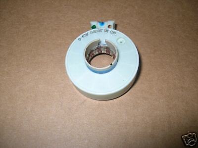
Not like this used one I paid $361 for!

The entire column - steering wheel, turn signals and all - was cheaper than that used sensor was and it says that they're all interchangeable from '97 to '04, so it makes more sense to upgrade the steering column to one that you can still buy parts for to me...?? Right?!
Any input on that idea?!
C1286 - Steering Sensor Bias Malfunction
C1287 - Steering Sensor Rate Malfunction
And getting messages to Service Active Handling and Service Vehicle Soon. Coming to the conclusion that I needed to replace my Steering Wheel Position Sensor (#26058286), I found out that GM has discontinued it and you cannot find one anywhere. After searching for two months, I found a used one on eBay for $361 - but kept hearing conflicting stories as to whether it could be used as a replacement or not due to the factory alignment pin not being in for initial installation...??C1287 - Steering Sensor Rate Malfunction
NOTE:
I wrote the guy that I bought the used sensor from and he replied:
"It was centered on removal so provided you install it just as you received it, it will work.
Can also be readjusted by anyone with a GM Tec II."
Can also be readjusted by anyone with a GM Tec II."
Looking through eBay hoping to get lucky and find one of these, I think I may have stumbled onto the best solution yet to fix this discontinued sensor problem and I'd like to get some feedback on my idea... I saw this and got to thinking:
I happened to notice that it already had a steering wheel position sensor on it and it was just like the ones you can still buy at Auto Zone for $85 all day long:
Not like this used one I paid $361 for!
The entire column - steering wheel, turn signals and all - was cheaper than that used sensor was and it says that they're all interchangeable from '97 to '04, so it makes more sense to upgrade the steering column to one that you can still buy parts for to me...?? Right?!
Any input on that idea?!

I have a similar knack, having bought the first Corvette I've owned in 33 years (99 FRC) last year. That being said, my take on it is that the steering positioning sensor is a dumb rheostat where straight ahead is zero resistance and the resistance increases or varies the further left or right you turn the wheel. All of them have three connectors which leads me to believe there is a signal in and a varying left and right signal out to other electronics. If the lower steering column is different in the three groups of cars (97-98, 99-00, 01 on) then your idea MAY work (a component fitment issue). If the columns are the same, then the electrical signal feeding other components is probably different, scuttling your idea. This is an educated guess. One solution IMHO would be obtain working sensors of each model grouping, and test them electrically with a VOM to find the output values. Good job for an EE out there, which I am not. My $.02.

Bill Curlee
Tech Contributor
close


Apr 15, 2026
- Member SinceDec 1999
- LocationAnthony TX
- Posts:32,910
- Veteran Field #1CI 6,7,8,9,11 Vet
- Veteran Field #2St. Jude Donor '08
-
Likes:458
-
Liked:2,402 Times in 1,716 Posts
Well,, I hope to add to this discussion as it has come up several times in the recent past.. Somewhere in my research, I remember reading the SWPS ZERO reading is 2.5 VDC. The Sensor Reff voltage as well as the voltages for all the other EBTCM sensors is 5 VDC.. Guess what? Its listed in the early C5 EBTCM description.  (see below)
Here is the write up for the 2001-2004 EBTCM System Operation. I will research and add the same info for the 99 C5 with JL4 option.
Document ID# 671064
2001 Chevrolet/Geo Corvette
--------------------------------------------------------------------------------
ABS Description and Operation
FIGURE BPMV and EBCM(c)
(1) Electronic Brake Control Module (EBCM)
(2) EBCM Electrical Connector
(3) EBCM to Brake Pressure Modulator Valve (BPMV) Screw
(4) BPMV Electrical Connector
(5) BPMV Pump Motor
(6) BPMV Bracket Bolts
(7) Rubber Isolator
(8) BPMV
(9) BPMV Solenoid Valves
(10) EBCM Solenoid Valve Coils
FIGURE BPMV Hydraulic Flow(c)
(1) Master Cylinder
(2) Master Cylinder Reservoir
(3) Pump
(4) Rear Master Cylinder Isolation Valve
(5) Rear Prime Valve
(6) Brake Pressure Modulator Valve (BPMV)
(7) Damper
(8) Right Rear Inlet Valve
(9) Accumulator
(10) Right Rear Brake
(11) Right Rear Outlet Valve
(12) Left Rear Outlet Valve
(13) Left Rear Brake
(14) Left Rear Inlet Valve
(15) Left Front Inlet Valve
(16) Left Front Brake
(17) Left Front Outlet Valve
(18) Right Front Brake
(19) Right Front Outlet Valve
(20) Accumulator
(21) Right Front Inlet Valve
(22) Damper
(23) Front Master Cylinder Isolation Valve
(24) Front Prime Valve
This vehicle is equipped with the Delco/Bosch 5.3 antilock braking system.
The vehicle is equipped with the following braking systems:
Antilock Brake System (ABS)
Dynamic Rear Proportioning (DRP)
Traction Control System (TCS)
Vehicle Stability Enhancement System (VSES) (w/JL4)
The following components are involved in the operation of the above systems:
Electronic Brake Control Module (EBCM) - The EBCM controls the system functions and detects failures. The EBCM contains the following components:
System Relay - The system relay is energized when the ignition is ON and no ABS DTCs are present. It supplies battery positive voltage to the solenoid valves and pump motor.
Vent Tube - The vent tube, located in the EBCM connector, is an opening to the internal cavity of the EBCM. It allows ventilation of the EBCM internals.
Brake Pressure Modulator Valve (BPMV) - The BPMV contains the hydraulic valves and pump motor that are controlled electrically by the EBCM. The BPMV uses a 4 circuit configuration with a front/rear split. The BPMV directs fluid from the reservoir of the master cylinder to the front wheels and fluid from the other reservoir to the rear wheels. The circuits are hydraulically isolated so that a leak or malfunction in one circuit will allow continued braking ability on the other.
Important
There is a rubber isolator located under the BPMV and on the mounting studs. The rubber isolators protect the BPMV and the EBCM from vehicle vibrations.
The BPMV contains the following components:
Pump Motor
Inlet Valves (one per wheel)
Outlet Valves (one per wheel)
Master Cylinder Isolation Valves (one per drive wheel)
Prime Valves (one per drive wheel)
Wheel Speed Sensors (WSS) - As the wheel spins, the wheel speed sensor produces an AC signal. The EBCM uses this AC signal to calculate wheel speed. The wheel speed sensors are replaceable only as part of the wheel hub and bearing assemblies.
Traction Control Switch - The TCS is manually disabled or enabled using the traction control switch.
Stoplamp Switch - The EBCM uses the stoplamp switch as an indication that the brake pedal is applied.
Lateral Accelerometer Sensor (w/JL4) - The EBCM uses the lateral accelerometer sensor as an indication of the lateral acceleration of the vehicle.
Yaw Rate Sensor (w/JL4) - The EBCM uses the yaw rate sensor as an indication of the yaw rate of the vehicle.
Steering Wheel Position Sensor (SWPS) (w/JL4) - The EBCM uses the SWPS as an indication of the position and rotation of the steering wheel.
Brake Fluid Pressure Sensor (w/JL4) - The brake fluid pressure sensor is attached to the BPMV. The EBCM uses the brake fluid pressure sensor as an indication of the brake fluid pressure in the BPMV.
Initialization Sequence
The EBCM performs 1 initialization test each ignition cycle. The initialization of the EBCM occurs when 1 set of the following conditions occur:
Both of the following conditions occur:
The EBCM detects that there is a minimum of 500 RPM from the PCM via a serial data message.
The stop lamp switch is not applied.
OR
Both of the following conditions occur:
The vehicle speed is greater than 16 km/h (10 mph).
The stop lamp switch is applied.
The initialization sequence may also be commanded with a scan tool.
The initialization sequence cycles each solenoid valve and the pump motor, as well as the necessary relays, for approximately 1.5 seconds to check component operation. The EBCM sets a DTC if any error is detected. The initialization sequence may be heard and felt while it is taking place, and is considered part of normal system operation.
The EBCM defines a drive cycle as the completion of the initialization sequence.
Antilock Brake System
When wheel slip is detected during a brake application, the ABS enters antilock mode. During antilock braking, hydraulic pressure in the individual wheel circuits is controlled to prevent any wheel from slipping. A separate hydraulic line and specific solenoid valves are provided for each wheel. The ABS can decrease, hold, or increase hydraulic pressure to each wheel brake. The ABS cannot, however, increase hydraulic pressure above the amount which is transmitted by the master cylinder during braking.
During antilock braking, a series of rapid pulsations is felt in the brake pedal. These pulsations are caused by the rapid changes in position of the individual solenoid valves as the EBCM responds to wheel speed sensor inputs and attempts to prevent wheel slip. These pedal pulsations are present only during antilock braking and stop when normal braking is resumed or when the vehicle comes to a stop. A ticking or popping noise may also be heard as the solenoid valves cycle rapidly. During antilock braking on dry pavement, intermittent chirping noises may be heard as the tires approach slipping. These noises and pedal pulsations are considered normal during antilock operation.
Vehicles equipped with ABS may be stopped by applying normal force to the brake pedal. Brake pedal operation during normal braking is no different than that of previous non-ABS systems. Maintaining a constant force on the brake pedal provides the shortest stopping distance while maintaining vehicle stability.
Pressure Hold
The EBCM closes the inlet valve and keeps the outlet valve closed in order to isolate the system when wheel slip occurs. This holds the pressure steady on the brake so that the hydraulic pressure does not increase or decrease.
Pressure Decrease
The EBCM decreases the pressure to individual wheels during a deceleration when wheel slip occurs. The inlet valve is closed and the outlet valve is opened. The excess fluid is stored in the accumulator until the return pump can return the fluid to the master cylinder.
Pressure Increase
The EBCM increases the pressure to individual wheels during a deceleration in order to reduce the speed of the wheel. The inlet valve is opened and the outlet valve is closed. The increased pressure is delivered from the master cylinder.
Dynamic Rear Proportioning (DRP)
The dynamic rear proportioning (DRP) is a control system that replaces the hydraulic proportioning function of the mechanical proportioning valve in the base brake system. The DRP control system is part of the operation software in the EBCM. The DRP uses active control with existing ABS in order to regulate the vehicle's rear brake pressure.
The red brake warning indicator is illuminated when the dynamic rear proportioning function is disabled.
Traction Control System (TCS) (NW9)
When drive wheel slip is noted while the brake is not applied, the EBCM will enter traction control mode.
First, the EBCM requests the PCM to reduce the amount of torque to the drive wheels via the requested torque signal circuit. The PCM reduces torque to the drive wheels by retarding spark timing and turning off fuel injectors. The PCM reports the amount torque delivered to the drive wheels via the delivered torque signal circuit.
If the engine torque reduction does not eliminate drive wheel slip, the EBCM will actively apply the drive wheel brakes. During traction control braking, hydraulic pressure in each drive wheel circuit is controlled to prevent the drive wheels from slipping. The master cylinder isolation valve closes in order to isolate the master cylinder from the rest of the hydraulic system. The prime valve then opens in order to allow the pump to accumulate brake fluid in order to build hydraulic pressure for braking. The drive wheel inlet and outlet solenoid valves then open and close in order to perform the following functions:
Pressure hold
Pressure increase
Pressure decrease
Vehicle Stability Enhancement System (VSES)
The vehicle stability enhancement system (VSES) includes an additional level of vehicle control to the EBCM. The VSES is activated by the EBCM calculating the desired yaw rate and comparing it to the actual yaw rate input. The desired yaw rate is calculated from measured steering wheel position, vehicle speed, and lateral acceleration. The difference between the desired yaw rate and actual yaw rate is the yaw rate error, which is a measurement of oversteer or understeer. If the yaw rate error becomes too large, the EBCM will attempt to correct the vehicle's yaw motion by applying differential braking to the left or right front wheel.
The amount of differential braking applied to the left or right front wheel is based on both the yaw rate error and side slip rate error. The side slip rate error is a function of the lateral acceleration minus the product of the yaw rate and vehicle speed. The yaw rate error and side slip rate error are combined to produce the total delta velocity error. When the delta velocity error becomes too large and the VSES system activates, the driver's steering inputs combined with the differential braking will attempt to bring the delta velocity error toward zero.
The EBCM also uses the input from the brake fluid pressure sensor for more accurate braking control during VSES.
The VSES activations generally occur during aggressive driving, in the turns or bumpy roads without much use of the accelerator pedal. When braking during VSES activation, the brake pedal will feel different than the ABS pedal pulsation. The brake pedal pulsates at a higher frequency during VSES activation.
Rear Stability Control
When the vehicle performs a high speed turn or curve, the EBCM will enter rear stability control mode. The vehicle speed is greater than 48 km/h (30 mph) and the vehicle lateral acceleration is greater than 0.6 g. The vehicle will exit rear stability control when the vehicle speed is less than 40 km/h (25 mph) or the vehicle lateral acceleration is less than 0.4 g.
During a rear stability control event, the EBCM performs a pressure increase on the outside rear brake and a pressure hold on the inside rear brake. The driver may hear the pump motor run and may feel a vibration in the brake pedal.
Brake System Indicator(s)
BRAKE
The IPC illuminates the brake indicator when the following occurs:
The IPC detects a low brake fluid condition (signal circuit is low).
The IPC detects the park brake is engaged (signal circuit low).
The IPC performs the displays test at the start of each ignition cycle. The indicator illuminates for approximately 3 seconds.
There is a Dynamic Rear Proportioning (DRP) failure.
LOW BRAKE FLUID
The IPC illuminates the LOW BRAKE FLUID indicator in the message center when the IPC receives a hardwire input from the brake fluid level sensor (signal is low).
ABS Indicator(s)
ABS
The IPC illuminates the ABS indicator when the following occurs:
The electronic brake control module (EBCM) detects a malfunction with the antilock brake system. The IPC receives a class 2 message from the EBCM requesting illumination.
The driver information center displays the SERVICE ABS message, SERVICE ACTIVE HNDLG message, TRAC/ACT HNDLG-ON/OFF message, TRACTION SYS ACTIVE message, or the TRACTION SYSTEM-ON/OFF message.
The IPC performs the displays test at the start of each ignition cycle. The indicator illuminates for approximately 3 seconds.
ABS ACTIVE
The IPC illuminates the ABS ACTIVE indicator in the message center when the electronic brake control module (EBCM) detects the antilock brake system is on. The IPC receives a class 2 message from the EBCM requesting illumination. The DIC displays this message for 3.5 seconds.
SERVICE ABS
The IPC illuminates the SERVICE ABS indicator in the message center when the following occurs:
The EBCM detects no anti-lock brakes on the vehicle. The IPC receives a class 2 message from the EBCM requesting illumination.
The IPC also illuminates the ABS indicator and the traction control and active handling system indicator along with a chime when this message is on.
Traction Control and Active Handling System Indicator(s)
ACT HNDLG-WARMING UP
The IPC illuminates the ACT HNDLG-WARMING UP indicator in the message center when the following occurs:
The active handling option needs to be present in order for this indicator to appear. The EBCM detects that the engine is on and the vehicle speed is at 6 mph (10 km/h) or below. The IPC receives a class 2 message from the EBCM. The DIC will display this message for 3.5 seconds and then turn off. A chime will sound will this message is displayed.
When this message is displayed the traction control and active handling system indicator turns on.
ACTIVE HANDLING
The active handling option needs to be present in order for this indicator to appear. The IPC illuminates the ACTIVE HANDLING indicator in the message center when the EBCM detects that the vehicle stability enhancement system is on. The IPC receives a class 2 message from the EBCM. The DIC will display this message for 3.5 seconds and then turn off.
COMPETITIVE DRIVING
The IPC illuminates the COMPETITIVE DRIVING indicator in the message center when the following occurs:
The active handling option needs to be present in order for this indicator to appear. The EBCM detects that competitive driving is on. The IPC receives a class 2 message from the EBCM.
When competitive driving is on and this message is displayed the traction control and active handling system indicator turns off.
When competitive driving is on and this message is displayed the TRAC/ACT HNLDG-ON/OFF message will be turned off in the message center, unless the TRAC/ACT HNDLG-ON was on before the COMPETITIVE DRIVING message turned on. If the TRAC/ACT HNDLG-ON was on before the COMPETITIVE DRIVING message then after the COMPETITIVE DRIVING message is displayed the TRAC/ACT HNDLG-OFF message will turn on.
SERVICE ACTIVE HNDLG
The IPC illuminates the SERVICE ACTIVE HNDLG indicator in the message center when the following occurs:
The active handling option needs to be present in order for this indicator to appear. The EBCM detects a problem with the active handling system. The IPC receives a class 2 message from the EBCM.
The IPC also illuminates the ABS indicator and the traction control and active handling system indicator along with a chime when this message is on.
SERVICE TRACTION SYSTEM
The IPC illuminates the SERVICE TRACTION SYSTEM indicator in the message center when the following occurs:
The EBCM detects that there is a problem with the traction control system. The IPC receives a class 2 message from the EBCM.
When the traction system is on and this message is displayed the traction control and active handling system indicator turns on.
The IPC will also illuminate the SERVICE ACTIVE HNDLG indicator after the SERVICE TRACTION SYSTEM indicator is displayed in the message center, when the active handling system is present.
Traction Control and Active Handling
The IPC illuminates the TRACTION indicator when the following occurs:
The electronic brake control module (EBCM) detects a traction control event. The IPC receives a class 2 message from the EBCM requesting illumination.
The driver information center displays the SERVICE ABS, the ACT HNDLG-WARMING UP, the SERVICE ACTIVE HNDLG, the SERVICE TRACTION SYSTEM, the TRAC/ACT HNDLG-ON/OFF, or the TRACTION SYSTEM-ON/OFF message.
The IPC performs the display test at the start of each ignition cycle. The indicator illuminates for approximately 3 seconds.
TRAC/ACT HNDLG-ON/OFF
The IPC illuminates the TRAC/ACT HNDLG-ON/OFF indicator in the message center when the following occurs:
The active handling option needs to be present in order for this indicator to appear. The EBCM detects that the traction/active control system switch is pressed on the console. The IPC receives a class 2 message from the EBCM. When the traction/active system is on, the DIC will display this message for 5 seconds and then turn off. If the traction/active system is off, the DIC will display this message continuously until the traction system is turned on.
When the traction/active system is on and this message is displayed the ABS indicator and the traction control and active handling system indicator turn on.
If the active handling system is inoperative, the IPC reverts to and illuminates the TRACTION SYSTEM-ON/OFF indicator after the SERVICE ACTIVE HNDLG message is displayed in the message center.
TRACTION SYS ACTIVE
The IPC illuminates the TRACTION SYS ACTIVE indicator in the message center when the electronic brake control module (EBCM) detects the traction control system is limiting wheel spin. The IPC receives a class 2 message from the EBCM requesting illumination. The DIC displays this message for 3.5 seconds. The ABS indicator also turns on when the TRACTION SYS ACTIVE indicator is on.
TRACTION SYSTEM-ON/OFF
The IPC illuminates the TRACTION SYSTEM-ON/OFF indicator in the message center when the following occurs:
The EBCM detects that the traction control system switch is pressed on the console. The IPC receives a class 2 message from the EBCM. When the traction system is on, the DIC will display this message for 5 seconds and then turn off. If the traction system is off, the DIC will display this message continuously until the traction system is turned on.
When the traction system is on and this message is displayed the ABS indicator and the traction control and active handling system indicator turn on.
The IPC illuminates the TRACTION SYSTEM-ON/OFF indicator after the SERVICE ACTIVE HNDLG message is displayed in the message center, when the active handling system is inoperative.
WARM UP COMPLETE
The active handling option needs to be present in order for this indicator to appear. The IPC illuminates the WARM UP COMPLETE indicator in the message center when the EBCM has completed the functional check of the active handling system. The IPC receives a class 2 message from the EBCM. The DIC will display this message for 3.5 seconds and then turn off. A chime will sound will this message is displayed.
--------------------------------------------------------------------------------
Document ID# 671064
2001 Chevrolet/Geo Corvette

Here is the info for the earlier C5 from the 99 Manual:
Document ID# 426762
1999 Chevrolet/Geo Corvette
--------------------------------------------------------------------------------
ABS Description
Brake Pressure Modulator Valve (BPMV)
FIGURE EBTCM/BPMV(c)
(1) Electronic Brake and Traction Control Module (EBTCM)
(2) Brake Pressure Modulator Valve (BPMV)
(3) Pump Motor
(4) Pump Motor Relay
(5) Solenoid Valve Relay
(6) Moisture Seal Between EBTCM and the BPMV
(7) EBTCM to BPMV Connectors
(8) EBTCM to BPMV Mounting Screws
The Brake Pressure Modulator Valve (BPMV) provides brake fluid modulation for each of the individual wheel circuits as required during an Antilock, Traction Control, or Active Handling (RPO JL4) event. During the Antilock mode, the BPMV can maintain or reduce brake fluid pressure independent of the pressure generated in the master cylinder. The BPMV does not provide more pressure than is applied by the master cylinder during an Antilock brake event. During a Traction Control or an Active Handling event the BPMV applies pressure independent of the master cylinder to the individual wheel circuits.
With the exception of the EBTCM, the Brake Pressure Modulator Valve (BPMV) is an integral, non-serviceable component. The BPMV should never be disassembled.
The BPMV consists of several other components which are described as follows:
Pump Motor
The BPMV contains a motor driven recirculation pump. The pump serves two purposes: 1) During ABS Reduce Pressure events, it transfers fluid from the brake calipers back to the master cylinder; and 2) During traction control, or an Active Handling event, the pump transfers fluid to the brake calipers. The pump and motor are located within the BPMV and are not serviced separately.
ABS Valves
The ABS valves decrease or maintain brake fluid pressure at the individual wheel circuits. There are four Inlet, and four Outlet solenoid valves. The solenoid valves maintain, increase, or decrease brake fluid pressure to the individual wheel circuits. The EBTCM commands the valves to their correct position during an Antilock, Traction Control, or Active Handling event. During antilock mode, the pressure in each hydraulic circuit can be held or released by activating the appropriate valves. The normal state of the Inlet valves is open, while the normal state of the Outlet valves is closed. This allows direct master cylinder pressure to the brakes during normal braking. The ABS valves are located within the BPMV and are not serviced separately.
Master Cylinder Isolation Valve (s)
There is one Master Cylinder Isolation Valve within the BPMV if the vehicle is equipped with ABS/TCS only. This valve isolates the master cylinder so the pump motor can build brake fluid pressure for the rear brakes during a traction event. There are two Master Cylinder Isolation Valves in the BPMV if the vehicle is equipped with Active Handling (RPO JL4). These valves isolate the master cylinder so the pump motor can build brake fluid pressure for the front and rear wheel brakes as needed during a Traction Control or Active Handling event.
Prime Valve (s)
There is one Prime Valve within the BPMV if the vehicle is equipped with ABS/TCS only. This valve allows the pump to draw fluid from the master cylinder reservoir, through the compensating ports in the master cylinder bore to build pressure in the individual wheel brakes as needed. There are two Prime Valves in the BPMV if the vehicle is equipped with Active Handling (RPO JL4). These valves allow the pump to draw fluid from the master cylinder reservoir, through the compensating ports in the master cylinder bore to build pressure in the individual wheel brakes as needed.
Electronic Brake And Traction Control Module (EBTCM)
The function of the EBTCM is to monitor inputs from all related sensors, determine wheel slip tendencies, yaw rate error if equipped with Active Handling (RPO JL4), control the brake system during Antilock, Traction Control, or Active Handling events and monitor the system for proper operation.
The EBTCM continuously checks the speed of each wheel to determine if any wheel is beginning to slip. If a wheel slip tendency is detected, the EBTCM commands appropriate valve positions to modulate brake fluid pressure in some or all of the hydraulic circuits to prevent wheel slip and provide optimum braking. The EBTCM continues to control pressure in individual hydraulic circuits until a slipping tendency is no longer present. If equipped with Active Handling the EBTCM also monitors the yaw rate error. If the yaw rate error becomes too large, the EBTCM will modulate brake fluid pressure to the individual wheel brakes as needed to restore the proper yaw rate error. If the EBTCM detects a system malfunction, it can disable the Antilock, Traction Control, and Active Handling functions and turn on the Antilock and/or Car Icon (TCS indicator) Indicators in the instrument cluster.
Pump Motor Relay and Solenoid Valve Relay
The pump motor relay provides power to the pump motor during Antilock braking, Traction Control or Active Handling (if equipped with RPO JL4). The Solenoid Valve Relay provides power to the solenoid valves in the Brake Pressure Modulator Valve (BPMV). Both of these relays are an integral part of the EBTCM and cannot be serviced separately.
Stoplamp Switch
The Stoplamp switch is an input to the EBTCM. The EBTCM uses the Stoplamp switch to tell when the brake pedal is being applied so that traction control can be disabled if necessary.
Wheel Speed Sensors
A Wheel Speed Sensor (WSS) is present at each wheel. The sensors transmit wheel speed information to the EBTCM by means of a small AC voltage. This voltage is generated by magnetic induction caused by passing a toothed sensor ring (part of the integral hub/bearing assembly) past a stationary sensor. The signal is transmitted to the EBTCM through shielded wiring to help reduce electro-magnetic interference that can cause false or noisy WSS inputs to the EBTCM.
FIGURE Front Wheel Speed Sensor(c)
(1) Front Wheel Speed Sensor
(2) Integral Hub/Bearing
The front wheel speed sensor is located in the hub/bearing assembly and is non-adjustable. Sensor gap is set at time of assembly.
FIGURE Rear Wheel Speed Sensor(c)
(1) Integral Hub/Bearing
(2) Rear Wheel Speed Sensor
The rear wheel speed sensors are mounted in the bearing assembly and are non-adjustable. Sensor gap is set at the time of assembly.
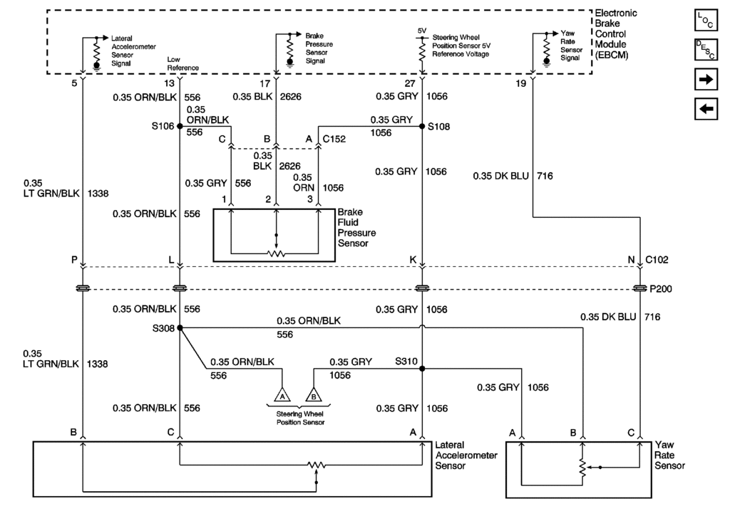
FIGURE Steering Wheel Position Sensor (SWPS)(c)
The Steering Wheel Position sensor has four outputs:
Digital output phase A
Digital output phase B
Index pulse (Non-Active Handling vehicles only)
Analog output
This information is used to calculate three things:
The front wheel's position when centered.
The front wheel's position when turning.
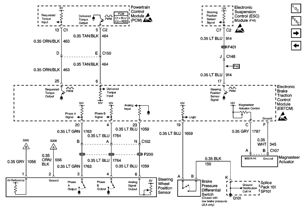
The vehicle's lateral acceleration. This is used for Magnasteer�2.
The EBTCM uses the digital input (Phase A and Phase B) from the Steering Wheel Position Sensor to calculate the direction the driver of the vehicle is trying to steer during an ABS and/or Active Handling (RPO JL4) event. This information is also used to calculate the vehicle's lateral acceleration for Magnasteer�2.
The EBTCM runs a centering routine when the vehicle speed goes above 10 Km/h (6 mph). When the vehicle reaches 10 Km/h (6 mph), the EBTCM monitors the Steering Wheel Position Sensor inputs (Phase A, Phase B and Analog voltage) to see if the steering wheel is moving. If the steering wheel is not moving for a set period of time then the EBTCM assumes the vehicle is going in a straight line. At this point, the EBTCM looks at the analog voltage signal and reads the voltage. This voltage, normally around 2.5V, is then considered the center position and the digital degrees also become zero at the same time. This centering routine is necessary to compensate for wear in the steering and suspension. Wear in the steering and suspension can result in a change in the relationship between the steering wheel and the front tires when driving in a straight line. By running the centering routine, the EBTCM can compensate for these changes by changing the digital and analog center position.
Traction Control/Active Handling System On/Off Switch
The Traction Control/Active Handling On/Off Switch is a momentary on switch that allows the driver to shut off the TCS and Active Handling (RPO JL4) if equipped, for personal or diagnostic reasons, by pressing and releasing the switch. If the vehicle is equipped with Active Handling, the TCS/Active Handling On/Off switch can be pressed and held for 5 seconds; this places the system in Competitive driving mode. Competitive driving mode turns the TCS off but still allows Active Handling to be active. The switch is located in the center console.
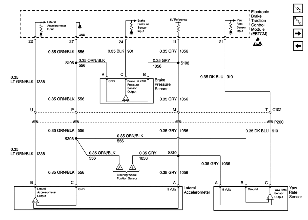
Lateral Accelerometer (RPO JL4)
The Lateral Accelerometer is a self contained unit which uses a reference voltage of 5 volts. The sensor's operating range is -1.5 - +1.5G, resulting in an output range of 0.25-4.75 volts. Zero lateral acceleration results in an output signal of 2.5 volts. The EBTCM uses the Lateral Accelerometer along with the Steering Wheel Position Sensor, and the Wheel Speed Sensors to calculate the desired yaw rate. The EBTCM compares the desired yaw rate to the actual yaw rate that is received from the Yaw Rate Sensor. The difference between the actual yaw rate and the desired yaw rate is the yaw rate error. The Lateral Accelerometer is also used for the Bank Angle Compensation calculation. The Bank Angle Compensation calculation is an important part of the Active Handling algorithm.
Yaw Rate Sensor (RPO JL4)
The Yaw Rate Sensor is a self contained unit which uses a reference voltage of 5 volts. The sensor's range is -75 - +75 degrees/second, resulting in a signal proportional output of 0.25-4.75 volts. Zero yaw rate is 2.5 volts. The EBTCM uses the Yaw Rate Sensor to determine the vehicles actual yaw rate to compare to the desired yaw rate. The difference between the actual yaw rate and the desired yaw rate is the yaw rate error.
Brake Pressure Sensor (RPO JL4)
(1) 0 Ring
(2) Brake Pressure Sensor
The Brake Pressure Sensor is a solid state self contained pressure sensor. The sensor has an operating range of 0.20-4.80 volts, resulting in a reading between 0-2000 psi. The EBTCM uses the input from the Brake Pressure Sensor during an Active Handling event to give more accurate control over the braking system.
Combination Valve (RPO JL4)
(1) Front brake line port from the master cylinder
(2) Adaptor
(3) Brake Pressure Sensor
(4) Front brake line port to the front brakes
(5) Rear brake line port to the rear brakes
(6) Proportioning Valve
(7) Rear brake line port from the master cylinder
(8) Brake Pressure Differential Valve
The combination valve consists of three components placed in housing.
Brake Pressure Sensor (3)
Brake Pressure Differential Switch (8)
Proportioning Valve (6)
--------------------------------------------------------------------------------
Document ID# 426762
1999 Chevrolet/Geo Corvette
Antilock Brake System
When wheel slip is noted during a brake application, the ABS will enter Antilock mode. During Antilock braking, hydraulic pressure in the individual wheel circuits is controlled to prevent any wheel from slipping. A separate hydraulic line and specific solenoid valves are provided for each wheel. The ABS can decrease, hold, or increase hydraulic pressure to each wheel brake. However, it cannot increase hydraulic pressure above the amount which is transmitted by the master cylinder during braking.
During Antilock braking, a series of rapid pulsation's will be felt in the brake pedal. These pulsation's are caused by the rapid changes in position of the individual solenoid valves as they respond to their desired wheel speed. This pedal pulsation is present during Antilock braking and will stop when normal braking is resumed or when the vehicle comes to a stop. A ticking or popping noise may also be heard as the solenoid valves rapidly cycle. During Antilock braking on dry pavement, the tires may make intermittent chirping noises as they approach slipping. These noises and pedal pulsation's should be considered normal during Antilock operation.
Vehicles equipped with ABS may be stopped by applying normal force to the brake pedal. Brake pedal operation during normal braking should be no different than previous systems. Maintaining a constant force on the pedal will provide the shortest stopping distance while maintaining vehicle stability.
Pressure Hold
When the EBTCM senses a wheel slip the EBTCM isolates the system by closing the Inlet valve and keeps the Outlet valve closed in the Brake Pressure Modulator Valve (BPMV). This holds the pressure steady on the brake so hydraulic pressure does not increase or decrease.
Pressure Decrease
If during the pressure hold mode the EBTCM still senses wheel speed slip it will decrease pressure to the brake. It does this by leaving the Inlet valve closed and opening the Outlet valve in the BPMV. The excess fluid is stored in the accumulator until it can be returned to the reservoir by the return pump.
Pressure Increase
If during the pressure hold or decrease mode the EBTCM senses that the wheel speed is too fast it will increase pressure to the brake. It does this by opening the Inlet valve and closing the Outlet valve in the BPMV. The increased pressure comes from the master cylinder and is related to the pressure applied to the brake pedal.
Traction Control
Traction control will not have any effect on the operation of the vehicle until the control module detects one or both of the rear wheels rotating faster than the front wheels. At this time the Electronic Brake and Traction Control Module (EBTCM) will request the Powertrain Control Module (PCM) to reduce the amount of torque applied to the drive wheels. The PCM does this by retarding timing and closing the throttle. The EBTCM will apply the rear brakes, thus reducing torque to the rear wheels. Once the rear wheels begin to rotate at the same speed as the front wheels, the system will return full control to the driver. During Traction Control mode, if the brake is applied to only one rear wheel, most of the torque from the engine will be directed to the other rear wheel which will improve the traction of the vehicle.
The braking is accomplished by closing the Rear Master Cylinder Isolation Valve; this isolates the master cylinder from the rest of the system. The Rear Prime valve opens to allow the pump to get brake fluid to build pressure for braking. The drive wheel circuit solenoids are energized as needed to allow for pressure hold, pressure increase, or pressure decrease.
The TCS may be deactivated by the driver if desired. In order to deactivate the TCS with the engine running, depress the TCS On/Off switch. The system will remain deactivated until the ignition switch is cycled, or the switch is pressed again.
Active Handling (RPO JL4)
Active Handling� includes an additional level of control by the EBTCM. Active Handling� monitors the Wheel Speed Sensors, Lateral Accelerometer, and the Steering Wheel Position Sensor inputs to calculate a desired vehicle yaw rate. The EBTCM then compares the desired vehicle yaw rate with the actual vehicle yaw rate supplied to the EBTCM from the Yaw Rate Sensor. The difference between the desired vehicle yaw rate and the actual vehicle yaw rate is the yaw rate error. Active Handling� keeps the yaw rate error to a minimum by selectively applying individual wheel brakes as necessary.
Before Active Handling� can be operational a Steering Wheel Position Sensor centering routine must be completed each time the vehicle is started and driven. The EBTCM runs a centering routine when the vehicle speed goes above 10 Km/h (6 mph). When the vehicle reaches 10 Km/h (6 mph), the EBTCM monitors the Steering Wheel Position Sensor inputs (Phase A, Phase B and Analog voltage) to see if the steering wheel is moving. If the steering wheel is not moving for a set period of time then the EBTCM assumes the vehicle is going in a straight line. At this point, the EBTCM looks at the analog voltage signal, this voltage, normally around 2.5V, is then considered the center position, the digital degrees also become zero at this time. This centering routine is necessary to compensate for wear in the steering and suspension. Wear in the steering and suspension can result in a change in the relationship between the steering wheel and the front tires when driving in a straight line, this can result in a false Steering Wheel Position Sensor signal sent to the EBTCM. By running the centering routine, the EBTCM can compensate for these changes by changing the digital and analog center position.
Once Active Handling� is operational the EBTCM monitors the yaw rate error. If the EBTCM sees an increase in the yaw rate error it will use differential braking on the individual wheel brakes as necessary. To correct for oversteer differential braking is used on the left or right rear wheel brakes. To correct for understeer differential braking is used on the left or right front wheel brakes.
Rear Brake Control
When the vehicle performs a high speed turn or curve, the EBCM will enter rear brake control mode. The vehicle speed is greater than 48 km/h (30 mph) and the vehicle lateral acceleration is greater than 0.6 g. The vehicle will exit rear brake control when the vehicle speed is less than 40 km/h (25 mph) or the vehicle lateral acceleration is less than 0.4 g.
During a rear brake control event, the EBCM performs a pressure increase on both rear brakes. The driver may feel a vibration in the brake pedal.
Magnasteer�
The Speed Dependent Steering System (Magnasteer�), incorporates its controller into the EBTCM.
Magnasteer� DTC C1241 will not cause any indicators to turn on.
Refer to Variable Effort Steering in Steering for DTC C1241 diagnostics and Magnasteer�2 description and operation.
Replacement Tires
The tire size is important for the performance of the ABS/TCS. The replacement tires should be the same size load range and construction as the original tires. Replace the tires in axle sets and only with tires of the same tire performance criteria specification number. Use of any other tire size or type may seriously affect ABS/TCS operation. For information on replacement tires for this vehicle, Refer to Tires and Wheels in Suspension.
BRAKE Warning Indicator
The red BRAKE Indicator in the instrument cluster will illuminate to warn the driver of conditions in the brake system which may result in reduced braking ability. The indicator will also illuminate when the parking brake is applied or not fully released, or if the brake fluid level switch is closed. The BRAKE warning lamp will stay illuminated until the condition has been repaired. Refer to Hydraulic Brake Diagnostic System Check in Hydraulic Brakes.
Antilock Indicator
The Antilock Indicator (ABS) is located in the instrument cluster and will illuminate if a malfunction in the ABS is detected by the Electronic Brake and Traction Control Module (EBTCM). The Antilock Indicator informs the driver that a condition exists which results in turning off the Antilock brake and traction control function. If only the Antilock Indicator is on, normal braking with full power assist is available. If the BRAKE and Antilock Indicators are on, a problem may exist in the hydraulic brake system. Refer to Hydraulic Brake Diagnostic System Check in Hydraulic Brakes. Conditions for the Antilock Indicator to turn on are as follows:
ABS malfunction detected. As previously described, the Antilock Indicator turns on when a problem has been found in the ABS. The Antilock Indicator indicates that the ABS and TCS have been disabled.
Instrument Panel Cluster bulb check. When the ignition is turned to on, the Antilock Indicator will turn on for approximately three seconds and then turn off.
Illumination of the BRAKE warning Indicator may indicate reduced braking ability.
Illumination of the Antilock Indicator without the BRAKE warning Indicator on indicates only that Antilock braking is no longer available. Power assisted braking without Antilock control is still available.
Refer to Hydraulic Brake Diagnostic System Check in Hydraulic Brakes for diagnosis of any condition which causes the BRAKE warning Indicator to illuminate.
Traction Control Indicator (Car Icon)
Indicator in the IPC notifies driver that the EBTCM has disabled the TCS.
Indicator is controlled by the IPC, with messages via serial data from the EBTCM, no hard wires.
Driver Information Center (DIC) Messages
Several messages related to the ABS/TCS may be displayed on the Driver Information Center (DIC), they are:
ABS ACTIVE: This message is displayed when ABS is active.
SERVICE ABS: This message is displayed continuously when an ABS fault exists.
SERVICE TRACTION SYSTEM: This message is displayed continuously when a TCS fault exists.
TRACTION SYS ACTIVE: This message is displayed when TCS is active.
TRACTION SYSTEM-OFF: This message is displayed continuously when TCS is turned off.
TRACTION SYSTEM-ON: This message is displayed for 3.5 seconds when TCS is turned on.
TRAC/ACT HNDLG-ON (JL4): This message is displayed for 3 seconds when TCS and Active Handling is turned on.
ACTIVE HANDLING (JL4): This message is displayed when Active Handling is active.
ACT/HNDLG-WARMING UP (JL4): This message is displayed if the SWPS has not been centered after 30 seconds. This message is also displayed if the underhood temperature sent from the BCM is to cold.
COMPETITIVE DRIVING (JL4): This message is displayed continuously when in competitive driving mode.
SERVICE ACTIVE HNDLG (JL4): This message is displayed continuously when an Active Handling fault exists.
TRAC/ACT HNDLG-OFF (JL4): This message is displayed continuously when TCS and Active Handling is turned off.
WARM UP COMPLETE (JL4): This message is displayed for 3.5 seconds after the SWPS is centered.
--------------------------------------------------------------------------------
Document ID# 426763
1999 Chevrolet/Geo Corvette
(see below)Here is the write up for the 2001-2004 EBTCM System Operation. I will research and add the same info for the 99 C5 with JL4 option.
Document ID# 671064
2001 Chevrolet/Geo Corvette
--------------------------------------------------------------------------------
ABS Description and Operation
FIGURE BPMV and EBCM(c)
(1) Electronic Brake Control Module (EBCM)
(2) EBCM Electrical Connector
(3) EBCM to Brake Pressure Modulator Valve (BPMV) Screw
(4) BPMV Electrical Connector
(5) BPMV Pump Motor
(6) BPMV Bracket Bolts
(7) Rubber Isolator
(8) BPMV
(9) BPMV Solenoid Valves
(10) EBCM Solenoid Valve Coils
FIGURE BPMV Hydraulic Flow(c)
(1) Master Cylinder
(2) Master Cylinder Reservoir
(3) Pump
(4) Rear Master Cylinder Isolation Valve
(5) Rear Prime Valve
(6) Brake Pressure Modulator Valve (BPMV)
(7) Damper
(8) Right Rear Inlet Valve
(9) Accumulator
(10) Right Rear Brake
(11) Right Rear Outlet Valve
(12) Left Rear Outlet Valve
(13) Left Rear Brake
(14) Left Rear Inlet Valve
(15) Left Front Inlet Valve
(16) Left Front Brake
(17) Left Front Outlet Valve
(18) Right Front Brake
(19) Right Front Outlet Valve
(20) Accumulator
(21) Right Front Inlet Valve
(22) Damper
(23) Front Master Cylinder Isolation Valve
(24) Front Prime Valve
This vehicle is equipped with the Delco/Bosch 5.3 antilock braking system.
The vehicle is equipped with the following braking systems:
Antilock Brake System (ABS)
Dynamic Rear Proportioning (DRP)
Traction Control System (TCS)
Vehicle Stability Enhancement System (VSES) (w/JL4)
The following components are involved in the operation of the above systems:
Electronic Brake Control Module (EBCM) - The EBCM controls the system functions and detects failures. The EBCM contains the following components:
System Relay - The system relay is energized when the ignition is ON and no ABS DTCs are present. It supplies battery positive voltage to the solenoid valves and pump motor.
Vent Tube - The vent tube, located in the EBCM connector, is an opening to the internal cavity of the EBCM. It allows ventilation of the EBCM internals.
Brake Pressure Modulator Valve (BPMV) - The BPMV contains the hydraulic valves and pump motor that are controlled electrically by the EBCM. The BPMV uses a 4 circuit configuration with a front/rear split. The BPMV directs fluid from the reservoir of the master cylinder to the front wheels and fluid from the other reservoir to the rear wheels. The circuits are hydraulically isolated so that a leak or malfunction in one circuit will allow continued braking ability on the other.
Important
There is a rubber isolator located under the BPMV and on the mounting studs. The rubber isolators protect the BPMV and the EBCM from vehicle vibrations.
The BPMV contains the following components:
Pump Motor
Inlet Valves (one per wheel)
Outlet Valves (one per wheel)
Master Cylinder Isolation Valves (one per drive wheel)
Prime Valves (one per drive wheel)
Wheel Speed Sensors (WSS) - As the wheel spins, the wheel speed sensor produces an AC signal. The EBCM uses this AC signal to calculate wheel speed. The wheel speed sensors are replaceable only as part of the wheel hub and bearing assemblies.
Traction Control Switch - The TCS is manually disabled or enabled using the traction control switch.
Stoplamp Switch - The EBCM uses the stoplamp switch as an indication that the brake pedal is applied.
Lateral Accelerometer Sensor (w/JL4) - The EBCM uses the lateral accelerometer sensor as an indication of the lateral acceleration of the vehicle.
Yaw Rate Sensor (w/JL4) - The EBCM uses the yaw rate sensor as an indication of the yaw rate of the vehicle.
Steering Wheel Position Sensor (SWPS) (w/JL4) - The EBCM uses the SWPS as an indication of the position and rotation of the steering wheel.
Brake Fluid Pressure Sensor (w/JL4) - The brake fluid pressure sensor is attached to the BPMV. The EBCM uses the brake fluid pressure sensor as an indication of the brake fluid pressure in the BPMV.
Initialization Sequence
The EBCM performs 1 initialization test each ignition cycle. The initialization of the EBCM occurs when 1 set of the following conditions occur:
Both of the following conditions occur:
The EBCM detects that there is a minimum of 500 RPM from the PCM via a serial data message.
The stop lamp switch is not applied.
OR
Both of the following conditions occur:
The vehicle speed is greater than 16 km/h (10 mph).
The stop lamp switch is applied.
The initialization sequence may also be commanded with a scan tool.
The initialization sequence cycles each solenoid valve and the pump motor, as well as the necessary relays, for approximately 1.5 seconds to check component operation. The EBCM sets a DTC if any error is detected. The initialization sequence may be heard and felt while it is taking place, and is considered part of normal system operation.
The EBCM defines a drive cycle as the completion of the initialization sequence.
Antilock Brake System
When wheel slip is detected during a brake application, the ABS enters antilock mode. During antilock braking, hydraulic pressure in the individual wheel circuits is controlled to prevent any wheel from slipping. A separate hydraulic line and specific solenoid valves are provided for each wheel. The ABS can decrease, hold, or increase hydraulic pressure to each wheel brake. The ABS cannot, however, increase hydraulic pressure above the amount which is transmitted by the master cylinder during braking.
During antilock braking, a series of rapid pulsations is felt in the brake pedal. These pulsations are caused by the rapid changes in position of the individual solenoid valves as the EBCM responds to wheel speed sensor inputs and attempts to prevent wheel slip. These pedal pulsations are present only during antilock braking and stop when normal braking is resumed or when the vehicle comes to a stop. A ticking or popping noise may also be heard as the solenoid valves cycle rapidly. During antilock braking on dry pavement, intermittent chirping noises may be heard as the tires approach slipping. These noises and pedal pulsations are considered normal during antilock operation.
Vehicles equipped with ABS may be stopped by applying normal force to the brake pedal. Brake pedal operation during normal braking is no different than that of previous non-ABS systems. Maintaining a constant force on the brake pedal provides the shortest stopping distance while maintaining vehicle stability.
Pressure Hold
The EBCM closes the inlet valve and keeps the outlet valve closed in order to isolate the system when wheel slip occurs. This holds the pressure steady on the brake so that the hydraulic pressure does not increase or decrease.
Pressure Decrease
The EBCM decreases the pressure to individual wheels during a deceleration when wheel slip occurs. The inlet valve is closed and the outlet valve is opened. The excess fluid is stored in the accumulator until the return pump can return the fluid to the master cylinder.
Pressure Increase
The EBCM increases the pressure to individual wheels during a deceleration in order to reduce the speed of the wheel. The inlet valve is opened and the outlet valve is closed. The increased pressure is delivered from the master cylinder.
Dynamic Rear Proportioning (DRP)
The dynamic rear proportioning (DRP) is a control system that replaces the hydraulic proportioning function of the mechanical proportioning valve in the base brake system. The DRP control system is part of the operation software in the EBCM. The DRP uses active control with existing ABS in order to regulate the vehicle's rear brake pressure.
The red brake warning indicator is illuminated when the dynamic rear proportioning function is disabled.
Traction Control System (TCS) (NW9)
When drive wheel slip is noted while the brake is not applied, the EBCM will enter traction control mode.
First, the EBCM requests the PCM to reduce the amount of torque to the drive wheels via the requested torque signal circuit. The PCM reduces torque to the drive wheels by retarding spark timing and turning off fuel injectors. The PCM reports the amount torque delivered to the drive wheels via the delivered torque signal circuit.
If the engine torque reduction does not eliminate drive wheel slip, the EBCM will actively apply the drive wheel brakes. During traction control braking, hydraulic pressure in each drive wheel circuit is controlled to prevent the drive wheels from slipping. The master cylinder isolation valve closes in order to isolate the master cylinder from the rest of the hydraulic system. The prime valve then opens in order to allow the pump to accumulate brake fluid in order to build hydraulic pressure for braking. The drive wheel inlet and outlet solenoid valves then open and close in order to perform the following functions:
Pressure hold
Pressure increase
Pressure decrease
Vehicle Stability Enhancement System (VSES)
The vehicle stability enhancement system (VSES) includes an additional level of vehicle control to the EBCM. The VSES is activated by the EBCM calculating the desired yaw rate and comparing it to the actual yaw rate input. The desired yaw rate is calculated from measured steering wheel position, vehicle speed, and lateral acceleration. The difference between the desired yaw rate and actual yaw rate is the yaw rate error, which is a measurement of oversteer or understeer. If the yaw rate error becomes too large, the EBCM will attempt to correct the vehicle's yaw motion by applying differential braking to the left or right front wheel.
The amount of differential braking applied to the left or right front wheel is based on both the yaw rate error and side slip rate error. The side slip rate error is a function of the lateral acceleration minus the product of the yaw rate and vehicle speed. The yaw rate error and side slip rate error are combined to produce the total delta velocity error. When the delta velocity error becomes too large and the VSES system activates, the driver's steering inputs combined with the differential braking will attempt to bring the delta velocity error toward zero.
The EBCM also uses the input from the brake fluid pressure sensor for more accurate braking control during VSES.
The VSES activations generally occur during aggressive driving, in the turns or bumpy roads without much use of the accelerator pedal. When braking during VSES activation, the brake pedal will feel different than the ABS pedal pulsation. The brake pedal pulsates at a higher frequency during VSES activation.
Rear Stability Control
When the vehicle performs a high speed turn or curve, the EBCM will enter rear stability control mode. The vehicle speed is greater than 48 km/h (30 mph) and the vehicle lateral acceleration is greater than 0.6 g. The vehicle will exit rear stability control when the vehicle speed is less than 40 km/h (25 mph) or the vehicle lateral acceleration is less than 0.4 g.
During a rear stability control event, the EBCM performs a pressure increase on the outside rear brake and a pressure hold on the inside rear brake. The driver may hear the pump motor run and may feel a vibration in the brake pedal.
Brake System Indicator(s)
BRAKE
The IPC illuminates the brake indicator when the following occurs:
The IPC detects a low brake fluid condition (signal circuit is low).
The IPC detects the park brake is engaged (signal circuit low).
The IPC performs the displays test at the start of each ignition cycle. The indicator illuminates for approximately 3 seconds.
There is a Dynamic Rear Proportioning (DRP) failure.
LOW BRAKE FLUID
The IPC illuminates the LOW BRAKE FLUID indicator in the message center when the IPC receives a hardwire input from the brake fluid level sensor (signal is low).
ABS Indicator(s)
ABS
The IPC illuminates the ABS indicator when the following occurs:
The electronic brake control module (EBCM) detects a malfunction with the antilock brake system. The IPC receives a class 2 message from the EBCM requesting illumination.
The driver information center displays the SERVICE ABS message, SERVICE ACTIVE HNDLG message, TRAC/ACT HNDLG-ON/OFF message, TRACTION SYS ACTIVE message, or the TRACTION SYSTEM-ON/OFF message.
The IPC performs the displays test at the start of each ignition cycle. The indicator illuminates for approximately 3 seconds.
ABS ACTIVE
The IPC illuminates the ABS ACTIVE indicator in the message center when the electronic brake control module (EBCM) detects the antilock brake system is on. The IPC receives a class 2 message from the EBCM requesting illumination. The DIC displays this message for 3.5 seconds.
SERVICE ABS
The IPC illuminates the SERVICE ABS indicator in the message center when the following occurs:
The EBCM detects no anti-lock brakes on the vehicle. The IPC receives a class 2 message from the EBCM requesting illumination.
The IPC also illuminates the ABS indicator and the traction control and active handling system indicator along with a chime when this message is on.
Traction Control and Active Handling System Indicator(s)
ACT HNDLG-WARMING UP
The IPC illuminates the ACT HNDLG-WARMING UP indicator in the message center when the following occurs:
The active handling option needs to be present in order for this indicator to appear. The EBCM detects that the engine is on and the vehicle speed is at 6 mph (10 km/h) or below. The IPC receives a class 2 message from the EBCM. The DIC will display this message for 3.5 seconds and then turn off. A chime will sound will this message is displayed.
When this message is displayed the traction control and active handling system indicator turns on.
ACTIVE HANDLING
The active handling option needs to be present in order for this indicator to appear. The IPC illuminates the ACTIVE HANDLING indicator in the message center when the EBCM detects that the vehicle stability enhancement system is on. The IPC receives a class 2 message from the EBCM. The DIC will display this message for 3.5 seconds and then turn off.
COMPETITIVE DRIVING
The IPC illuminates the COMPETITIVE DRIVING indicator in the message center when the following occurs:
The active handling option needs to be present in order for this indicator to appear. The EBCM detects that competitive driving is on. The IPC receives a class 2 message from the EBCM.
When competitive driving is on and this message is displayed the traction control and active handling system indicator turns off.
When competitive driving is on and this message is displayed the TRAC/ACT HNLDG-ON/OFF message will be turned off in the message center, unless the TRAC/ACT HNDLG-ON was on before the COMPETITIVE DRIVING message turned on. If the TRAC/ACT HNDLG-ON was on before the COMPETITIVE DRIVING message then after the COMPETITIVE DRIVING message is displayed the TRAC/ACT HNDLG-OFF message will turn on.
SERVICE ACTIVE HNDLG
The IPC illuminates the SERVICE ACTIVE HNDLG indicator in the message center when the following occurs:
The active handling option needs to be present in order for this indicator to appear. The EBCM detects a problem with the active handling system. The IPC receives a class 2 message from the EBCM.
The IPC also illuminates the ABS indicator and the traction control and active handling system indicator along with a chime when this message is on.
SERVICE TRACTION SYSTEM
The IPC illuminates the SERVICE TRACTION SYSTEM indicator in the message center when the following occurs:
The EBCM detects that there is a problem with the traction control system. The IPC receives a class 2 message from the EBCM.
When the traction system is on and this message is displayed the traction control and active handling system indicator turns on.
The IPC will also illuminate the SERVICE ACTIVE HNDLG indicator after the SERVICE TRACTION SYSTEM indicator is displayed in the message center, when the active handling system is present.
Traction Control and Active Handling
The IPC illuminates the TRACTION indicator when the following occurs:
The electronic brake control module (EBCM) detects a traction control event. The IPC receives a class 2 message from the EBCM requesting illumination.
The driver information center displays the SERVICE ABS, the ACT HNDLG-WARMING UP, the SERVICE ACTIVE HNDLG, the SERVICE TRACTION SYSTEM, the TRAC/ACT HNDLG-ON/OFF, or the TRACTION SYSTEM-ON/OFF message.
The IPC performs the display test at the start of each ignition cycle. The indicator illuminates for approximately 3 seconds.
TRAC/ACT HNDLG-ON/OFF
The IPC illuminates the TRAC/ACT HNDLG-ON/OFF indicator in the message center when the following occurs:
The active handling option needs to be present in order for this indicator to appear. The EBCM detects that the traction/active control system switch is pressed on the console. The IPC receives a class 2 message from the EBCM. When the traction/active system is on, the DIC will display this message for 5 seconds and then turn off. If the traction/active system is off, the DIC will display this message continuously until the traction system is turned on.
When the traction/active system is on and this message is displayed the ABS indicator and the traction control and active handling system indicator turn on.
If the active handling system is inoperative, the IPC reverts to and illuminates the TRACTION SYSTEM-ON/OFF indicator after the SERVICE ACTIVE HNDLG message is displayed in the message center.
TRACTION SYS ACTIVE
The IPC illuminates the TRACTION SYS ACTIVE indicator in the message center when the electronic brake control module (EBCM) detects the traction control system is limiting wheel spin. The IPC receives a class 2 message from the EBCM requesting illumination. The DIC displays this message for 3.5 seconds. The ABS indicator also turns on when the TRACTION SYS ACTIVE indicator is on.
TRACTION SYSTEM-ON/OFF
The IPC illuminates the TRACTION SYSTEM-ON/OFF indicator in the message center when the following occurs:
The EBCM detects that the traction control system switch is pressed on the console. The IPC receives a class 2 message from the EBCM. When the traction system is on, the DIC will display this message for 5 seconds and then turn off. If the traction system is off, the DIC will display this message continuously until the traction system is turned on.
When the traction system is on and this message is displayed the ABS indicator and the traction control and active handling system indicator turn on.
The IPC illuminates the TRACTION SYSTEM-ON/OFF indicator after the SERVICE ACTIVE HNDLG message is displayed in the message center, when the active handling system is inoperative.
WARM UP COMPLETE
The active handling option needs to be present in order for this indicator to appear. The IPC illuminates the WARM UP COMPLETE indicator in the message center when the EBCM has completed the functional check of the active handling system. The IPC receives a class 2 message from the EBCM. The DIC will display this message for 3.5 seconds and then turn off. A chime will sound will this message is displayed.
--------------------------------------------------------------------------------
Document ID# 671064
2001 Chevrolet/Geo Corvette
Here is the info for the earlier C5 from the 99 Manual:
Document ID# 426762
1999 Chevrolet/Geo Corvette
--------------------------------------------------------------------------------
ABS Description
Brake Pressure Modulator Valve (BPMV)
FIGURE EBTCM/BPMV(c)
(1) Electronic Brake and Traction Control Module (EBTCM)
(2) Brake Pressure Modulator Valve (BPMV)
(3) Pump Motor
(4) Pump Motor Relay
(5) Solenoid Valve Relay
(6) Moisture Seal Between EBTCM and the BPMV
(7) EBTCM to BPMV Connectors
(8) EBTCM to BPMV Mounting Screws
The Brake Pressure Modulator Valve (BPMV) provides brake fluid modulation for each of the individual wheel circuits as required during an Antilock, Traction Control, or Active Handling (RPO JL4) event. During the Antilock mode, the BPMV can maintain or reduce brake fluid pressure independent of the pressure generated in the master cylinder. The BPMV does not provide more pressure than is applied by the master cylinder during an Antilock brake event. During a Traction Control or an Active Handling event the BPMV applies pressure independent of the master cylinder to the individual wheel circuits.
With the exception of the EBTCM, the Brake Pressure Modulator Valve (BPMV) is an integral, non-serviceable component. The BPMV should never be disassembled.
The BPMV consists of several other components which are described as follows:
Pump Motor
The BPMV contains a motor driven recirculation pump. The pump serves two purposes: 1) During ABS Reduce Pressure events, it transfers fluid from the brake calipers back to the master cylinder; and 2) During traction control, or an Active Handling event, the pump transfers fluid to the brake calipers. The pump and motor are located within the BPMV and are not serviced separately.
ABS Valves
The ABS valves decrease or maintain brake fluid pressure at the individual wheel circuits. There are four Inlet, and four Outlet solenoid valves. The solenoid valves maintain, increase, or decrease brake fluid pressure to the individual wheel circuits. The EBTCM commands the valves to their correct position during an Antilock, Traction Control, or Active Handling event. During antilock mode, the pressure in each hydraulic circuit can be held or released by activating the appropriate valves. The normal state of the Inlet valves is open, while the normal state of the Outlet valves is closed. This allows direct master cylinder pressure to the brakes during normal braking. The ABS valves are located within the BPMV and are not serviced separately.
Master Cylinder Isolation Valve (s)
There is one Master Cylinder Isolation Valve within the BPMV if the vehicle is equipped with ABS/TCS only. This valve isolates the master cylinder so the pump motor can build brake fluid pressure for the rear brakes during a traction event. There are two Master Cylinder Isolation Valves in the BPMV if the vehicle is equipped with Active Handling (RPO JL4). These valves isolate the master cylinder so the pump motor can build brake fluid pressure for the front and rear wheel brakes as needed during a Traction Control or Active Handling event.
Prime Valve (s)
There is one Prime Valve within the BPMV if the vehicle is equipped with ABS/TCS only. This valve allows the pump to draw fluid from the master cylinder reservoir, through the compensating ports in the master cylinder bore to build pressure in the individual wheel brakes as needed. There are two Prime Valves in the BPMV if the vehicle is equipped with Active Handling (RPO JL4). These valves allow the pump to draw fluid from the master cylinder reservoir, through the compensating ports in the master cylinder bore to build pressure in the individual wheel brakes as needed.
Electronic Brake And Traction Control Module (EBTCM)
The function of the EBTCM is to monitor inputs from all related sensors, determine wheel slip tendencies, yaw rate error if equipped with Active Handling (RPO JL4), control the brake system during Antilock, Traction Control, or Active Handling events and monitor the system for proper operation.
The EBTCM continuously checks the speed of each wheel to determine if any wheel is beginning to slip. If a wheel slip tendency is detected, the EBTCM commands appropriate valve positions to modulate brake fluid pressure in some or all of the hydraulic circuits to prevent wheel slip and provide optimum braking. The EBTCM continues to control pressure in individual hydraulic circuits until a slipping tendency is no longer present. If equipped with Active Handling the EBTCM also monitors the yaw rate error. If the yaw rate error becomes too large, the EBTCM will modulate brake fluid pressure to the individual wheel brakes as needed to restore the proper yaw rate error. If the EBTCM detects a system malfunction, it can disable the Antilock, Traction Control, and Active Handling functions and turn on the Antilock and/or Car Icon (TCS indicator) Indicators in the instrument cluster.
Pump Motor Relay and Solenoid Valve Relay
The pump motor relay provides power to the pump motor during Antilock braking, Traction Control or Active Handling (if equipped with RPO JL4). The Solenoid Valve Relay provides power to the solenoid valves in the Brake Pressure Modulator Valve (BPMV). Both of these relays are an integral part of the EBTCM and cannot be serviced separately.
Stoplamp Switch
The Stoplamp switch is an input to the EBTCM. The EBTCM uses the Stoplamp switch to tell when the brake pedal is being applied so that traction control can be disabled if necessary.
Wheel Speed Sensors
A Wheel Speed Sensor (WSS) is present at each wheel. The sensors transmit wheel speed information to the EBTCM by means of a small AC voltage. This voltage is generated by magnetic induction caused by passing a toothed sensor ring (part of the integral hub/bearing assembly) past a stationary sensor. The signal is transmitted to the EBTCM through shielded wiring to help reduce electro-magnetic interference that can cause false or noisy WSS inputs to the EBTCM.
FIGURE Front Wheel Speed Sensor(c)
(1) Front Wheel Speed Sensor
(2) Integral Hub/Bearing
The front wheel speed sensor is located in the hub/bearing assembly and is non-adjustable. Sensor gap is set at time of assembly.
FIGURE Rear Wheel Speed Sensor(c)
(1) Integral Hub/Bearing
(2) Rear Wheel Speed Sensor
The rear wheel speed sensors are mounted in the bearing assembly and are non-adjustable. Sensor gap is set at the time of assembly.
FIGURE Steering Wheel Position Sensor (SWPS)(c)
The Steering Wheel Position sensor has four outputs:
Digital output phase A
Digital output phase B
Index pulse (Non-Active Handling vehicles only)
Analog output
This information is used to calculate three things:
The front wheel's position when centered.
The front wheel's position when turning.
The vehicle's lateral acceleration. This is used for Magnasteer�2.
The EBTCM uses the digital input (Phase A and Phase B) from the Steering Wheel Position Sensor to calculate the direction the driver of the vehicle is trying to steer during an ABS and/or Active Handling (RPO JL4) event. This information is also used to calculate the vehicle's lateral acceleration for Magnasteer�2.
The EBTCM runs a centering routine when the vehicle speed goes above 10 Km/h (6 mph). When the vehicle reaches 10 Km/h (6 mph), the EBTCM monitors the Steering Wheel Position Sensor inputs (Phase A, Phase B and Analog voltage) to see if the steering wheel is moving. If the steering wheel is not moving for a set period of time then the EBTCM assumes the vehicle is going in a straight line. At this point, the EBTCM looks at the analog voltage signal and reads the voltage. This voltage, normally around 2.5V, is then considered the center position and the digital degrees also become zero at the same time. This centering routine is necessary to compensate for wear in the steering and suspension. Wear in the steering and suspension can result in a change in the relationship between the steering wheel and the front tires when driving in a straight line. By running the centering routine, the EBTCM can compensate for these changes by changing the digital and analog center position.
Traction Control/Active Handling System On/Off Switch
The Traction Control/Active Handling On/Off Switch is a momentary on switch that allows the driver to shut off the TCS and Active Handling (RPO JL4) if equipped, for personal or diagnostic reasons, by pressing and releasing the switch. If the vehicle is equipped with Active Handling, the TCS/Active Handling On/Off switch can be pressed and held for 5 seconds; this places the system in Competitive driving mode. Competitive driving mode turns the TCS off but still allows Active Handling to be active. The switch is located in the center console.
Lateral Accelerometer (RPO JL4)
The Lateral Accelerometer is a self contained unit which uses a reference voltage of 5 volts. The sensor's operating range is -1.5 - +1.5G, resulting in an output range of 0.25-4.75 volts. Zero lateral acceleration results in an output signal of 2.5 volts. The EBTCM uses the Lateral Accelerometer along with the Steering Wheel Position Sensor, and the Wheel Speed Sensors to calculate the desired yaw rate. The EBTCM compares the desired yaw rate to the actual yaw rate that is received from the Yaw Rate Sensor. The difference between the actual yaw rate and the desired yaw rate is the yaw rate error. The Lateral Accelerometer is also used for the Bank Angle Compensation calculation. The Bank Angle Compensation calculation is an important part of the Active Handling algorithm.
Yaw Rate Sensor (RPO JL4)
The Yaw Rate Sensor is a self contained unit which uses a reference voltage of 5 volts. The sensor's range is -75 - +75 degrees/second, resulting in a signal proportional output of 0.25-4.75 volts. Zero yaw rate is 2.5 volts. The EBTCM uses the Yaw Rate Sensor to determine the vehicles actual yaw rate to compare to the desired yaw rate. The difference between the actual yaw rate and the desired yaw rate is the yaw rate error.
Brake Pressure Sensor (RPO JL4)
(1) 0 Ring
(2) Brake Pressure Sensor
The Brake Pressure Sensor is a solid state self contained pressure sensor. The sensor has an operating range of 0.20-4.80 volts, resulting in a reading between 0-2000 psi. The EBTCM uses the input from the Brake Pressure Sensor during an Active Handling event to give more accurate control over the braking system.
Combination Valve (RPO JL4)
(1) Front brake line port from the master cylinder
(2) Adaptor
(3) Brake Pressure Sensor
(4) Front brake line port to the front brakes
(5) Rear brake line port to the rear brakes
(6) Proportioning Valve
(7) Rear brake line port from the master cylinder
(8) Brake Pressure Differential Valve
The combination valve consists of three components placed in housing.
Brake Pressure Sensor (3)
Brake Pressure Differential Switch (8)
Proportioning Valve (6)
--------------------------------------------------------------------------------
Document ID# 426762
1999 Chevrolet/Geo Corvette
Antilock Brake System
When wheel slip is noted during a brake application, the ABS will enter Antilock mode. During Antilock braking, hydraulic pressure in the individual wheel circuits is controlled to prevent any wheel from slipping. A separate hydraulic line and specific solenoid valves are provided for each wheel. The ABS can decrease, hold, or increase hydraulic pressure to each wheel brake. However, it cannot increase hydraulic pressure above the amount which is transmitted by the master cylinder during braking.
During Antilock braking, a series of rapid pulsation's will be felt in the brake pedal. These pulsation's are caused by the rapid changes in position of the individual solenoid valves as they respond to their desired wheel speed. This pedal pulsation is present during Antilock braking and will stop when normal braking is resumed or when the vehicle comes to a stop. A ticking or popping noise may also be heard as the solenoid valves rapidly cycle. During Antilock braking on dry pavement, the tires may make intermittent chirping noises as they approach slipping. These noises and pedal pulsation's should be considered normal during Antilock operation.
Vehicles equipped with ABS may be stopped by applying normal force to the brake pedal. Brake pedal operation during normal braking should be no different than previous systems. Maintaining a constant force on the pedal will provide the shortest stopping distance while maintaining vehicle stability.
Pressure Hold
When the EBTCM senses a wheel slip the EBTCM isolates the system by closing the Inlet valve and keeps the Outlet valve closed in the Brake Pressure Modulator Valve (BPMV). This holds the pressure steady on the brake so hydraulic pressure does not increase or decrease.
Pressure Decrease
If during the pressure hold mode the EBTCM still senses wheel speed slip it will decrease pressure to the brake. It does this by leaving the Inlet valve closed and opening the Outlet valve in the BPMV. The excess fluid is stored in the accumulator until it can be returned to the reservoir by the return pump.
Pressure Increase
If during the pressure hold or decrease mode the EBTCM senses that the wheel speed is too fast it will increase pressure to the brake. It does this by opening the Inlet valve and closing the Outlet valve in the BPMV. The increased pressure comes from the master cylinder and is related to the pressure applied to the brake pedal.
Traction Control
Traction control will not have any effect on the operation of the vehicle until the control module detects one or both of the rear wheels rotating faster than the front wheels. At this time the Electronic Brake and Traction Control Module (EBTCM) will request the Powertrain Control Module (PCM) to reduce the amount of torque applied to the drive wheels. The PCM does this by retarding timing and closing the throttle. The EBTCM will apply the rear brakes, thus reducing torque to the rear wheels. Once the rear wheels begin to rotate at the same speed as the front wheels, the system will return full control to the driver. During Traction Control mode, if the brake is applied to only one rear wheel, most of the torque from the engine will be directed to the other rear wheel which will improve the traction of the vehicle.
The braking is accomplished by closing the Rear Master Cylinder Isolation Valve; this isolates the master cylinder from the rest of the system. The Rear Prime valve opens to allow the pump to get brake fluid to build pressure for braking. The drive wheel circuit solenoids are energized as needed to allow for pressure hold, pressure increase, or pressure decrease.
The TCS may be deactivated by the driver if desired. In order to deactivate the TCS with the engine running, depress the TCS On/Off switch. The system will remain deactivated until the ignition switch is cycled, or the switch is pressed again.
Active Handling (RPO JL4)
Active Handling� includes an additional level of control by the EBTCM. Active Handling� monitors the Wheel Speed Sensors, Lateral Accelerometer, and the Steering Wheel Position Sensor inputs to calculate a desired vehicle yaw rate. The EBTCM then compares the desired vehicle yaw rate with the actual vehicle yaw rate supplied to the EBTCM from the Yaw Rate Sensor. The difference between the desired vehicle yaw rate and the actual vehicle yaw rate is the yaw rate error. Active Handling� keeps the yaw rate error to a minimum by selectively applying individual wheel brakes as necessary.
Before Active Handling� can be operational a Steering Wheel Position Sensor centering routine must be completed each time the vehicle is started and driven. The EBTCM runs a centering routine when the vehicle speed goes above 10 Km/h (6 mph). When the vehicle reaches 10 Km/h (6 mph), the EBTCM monitors the Steering Wheel Position Sensor inputs (Phase A, Phase B and Analog voltage) to see if the steering wheel is moving. If the steering wheel is not moving for a set period of time then the EBTCM assumes the vehicle is going in a straight line. At this point, the EBTCM looks at the analog voltage signal, this voltage, normally around 2.5V, is then considered the center position, the digital degrees also become zero at this time. This centering routine is necessary to compensate for wear in the steering and suspension. Wear in the steering and suspension can result in a change in the relationship between the steering wheel and the front tires when driving in a straight line, this can result in a false Steering Wheel Position Sensor signal sent to the EBTCM. By running the centering routine, the EBTCM can compensate for these changes by changing the digital and analog center position.
Once Active Handling� is operational the EBTCM monitors the yaw rate error. If the EBTCM sees an increase in the yaw rate error it will use differential braking on the individual wheel brakes as necessary. To correct for oversteer differential braking is used on the left or right rear wheel brakes. To correct for understeer differential braking is used on the left or right front wheel brakes.
Rear Brake Control
When the vehicle performs a high speed turn or curve, the EBCM will enter rear brake control mode. The vehicle speed is greater than 48 km/h (30 mph) and the vehicle lateral acceleration is greater than 0.6 g. The vehicle will exit rear brake control when the vehicle speed is less than 40 km/h (25 mph) or the vehicle lateral acceleration is less than 0.4 g.
During a rear brake control event, the EBCM performs a pressure increase on both rear brakes. The driver may feel a vibration in the brake pedal.
Magnasteer�
The Speed Dependent Steering System (Magnasteer�), incorporates its controller into the EBTCM.
Magnasteer� DTC C1241 will not cause any indicators to turn on.
Refer to Variable Effort Steering in Steering for DTC C1241 diagnostics and Magnasteer�2 description and operation.
Replacement Tires
The tire size is important for the performance of the ABS/TCS. The replacement tires should be the same size load range and construction as the original tires. Replace the tires in axle sets and only with tires of the same tire performance criteria specification number. Use of any other tire size or type may seriously affect ABS/TCS operation. For information on replacement tires for this vehicle, Refer to Tires and Wheels in Suspension.
BRAKE Warning Indicator
The red BRAKE Indicator in the instrument cluster will illuminate to warn the driver of conditions in the brake system which may result in reduced braking ability. The indicator will also illuminate when the parking brake is applied or not fully released, or if the brake fluid level switch is closed. The BRAKE warning lamp will stay illuminated until the condition has been repaired. Refer to Hydraulic Brake Diagnostic System Check in Hydraulic Brakes.
Antilock Indicator
The Antilock Indicator (ABS) is located in the instrument cluster and will illuminate if a malfunction in the ABS is detected by the Electronic Brake and Traction Control Module (EBTCM). The Antilock Indicator informs the driver that a condition exists which results in turning off the Antilock brake and traction control function. If only the Antilock Indicator is on, normal braking with full power assist is available. If the BRAKE and Antilock Indicators are on, a problem may exist in the hydraulic brake system. Refer to Hydraulic Brake Diagnostic System Check in Hydraulic Brakes. Conditions for the Antilock Indicator to turn on are as follows:
ABS malfunction detected. As previously described, the Antilock Indicator turns on when a problem has been found in the ABS. The Antilock Indicator indicates that the ABS and TCS have been disabled.
Instrument Panel Cluster bulb check. When the ignition is turned to on, the Antilock Indicator will turn on for approximately three seconds and then turn off.
Illumination of the BRAKE warning Indicator may indicate reduced braking ability.
Illumination of the Antilock Indicator without the BRAKE warning Indicator on indicates only that Antilock braking is no longer available. Power assisted braking without Antilock control is still available.
Refer to Hydraulic Brake Diagnostic System Check in Hydraulic Brakes for diagnosis of any condition which causes the BRAKE warning Indicator to illuminate.
Traction Control Indicator (Car Icon)
Indicator in the IPC notifies driver that the EBTCM has disabled the TCS.
Indicator is controlled by the IPC, with messages via serial data from the EBTCM, no hard wires.
Driver Information Center (DIC) Messages
Several messages related to the ABS/TCS may be displayed on the Driver Information Center (DIC), they are:
ABS ACTIVE: This message is displayed when ABS is active.
SERVICE ABS: This message is displayed continuously when an ABS fault exists.
SERVICE TRACTION SYSTEM: This message is displayed continuously when a TCS fault exists.
TRACTION SYS ACTIVE: This message is displayed when TCS is active.
TRACTION SYSTEM-OFF: This message is displayed continuously when TCS is turned off.
TRACTION SYSTEM-ON: This message is displayed for 3.5 seconds when TCS is turned on.
TRAC/ACT HNDLG-ON (JL4): This message is displayed for 3 seconds when TCS and Active Handling is turned on.
ACTIVE HANDLING (JL4): This message is displayed when Active Handling is active.
ACT/HNDLG-WARMING UP (JL4): This message is displayed if the SWPS has not been centered after 30 seconds. This message is also displayed if the underhood temperature sent from the BCM is to cold.
COMPETITIVE DRIVING (JL4): This message is displayed continuously when in competitive driving mode.
SERVICE ACTIVE HNDLG (JL4): This message is displayed continuously when an Active Handling fault exists.
TRAC/ACT HNDLG-OFF (JL4): This message is displayed continuously when TCS and Active Handling is turned off.
WARM UP COMPLETE (JL4): This message is displayed for 3.5 seconds after the SWPS is centered.
--------------------------------------------------------------------------------
Document ID# 426763
1999 Chevrolet/Geo Corvette

I just had a 2000 Corvette with a C1287 code and I was able to use a steering sensor from a 97 Corvette to fix it. It is a hair different. There is a tab on it that is in the way, but once that is taken care of, poof. #26055808. Hope this helps you guys.
Every time I read another one of these threads about this issue, I'm soooooo glad I don't have AH on my '99. 
lionelhutz
Race Director

close


Yesterday
- Member SinceApr 2007
- LocationSouth Western Ontario
- Posts:11,150
-
Likes:157
-
Liked:890 Times in 757 Posts
Quote:
Nice work trying parts and figuring out what will work.Originally Posted by ysrjunkie
I just had a 2000 Corvette with a C1287 code and I was able to use a steering sensor from a 97 Corvette to fix it. It is a hair different. There is a tab on it that is in the way, but once that is taken care of, poof. #26055808. Hope this helps you guys.
For the record, the 2001-up sensor would not work. Both early and late have the A & B digital signals, but the early model sensor also has an analog signal that the late model sensor is missing.
Sorry guys, but I thought I had it fixed. I drove the car when I posted just back and forth in the shop and the light did not come on, but today when I took it out on the road, the service light came back on with a C1281. I thought I found the missing link. Sorry.
Corvette Stories
The Best of Corvette for Corvette Enthusiasts
Explore

Corvette ZR1X Will Be Pacing the Indy 500, And Could Probably Race, Too!
Verdad Gallardo
Top 10 Corvettes Coming to Mecum Indy 2026!
Brett Foote
Top 10 C9 Corvette MUST-HAVES to Fix These C8 Generation Flaws!
Michael S. Palmer
10 Revolutionary 'Corvette Firsts' Most People Don't Know
Joe Kucinski
5 Reasons to Upgrade to an LS6-Powered Corvette; 5 Reasons to Stay LT2
Michael S. Palmer
2027 Corvette vs The World: Every C8 vs Its Closest Competitor
Joe Kucinski
10 Most Common Corvette Problems of the Last 20 Years!
Joe Kucinski
5 MOST and 5 LEAST Popular Corvette Model Years in History!
Joe Kucinski
2027 Corvette Buyer's Guide: Everything You Need to Know!
Joe Kucinski


Bringing back an old topic but did you equate the C1281 to the 97 SWPS or something completely different? I'm now on my second SWPS as I had to buy a used one the second time and it worked for a while but it's now flaking out also. This car is getting expensive!!
Dave
Dave

I've had (2) incidents where this code (C1288) came and went.
Both at low speed and IIRC at wheel lock or close in my driveway.
I found this in this thread
"Before Active Handling� can be operational a Steering Wheel Position Sensor centering routine must be completed each time the vehicle is started and driven. The EBTCM runs a centering routine when the vehicle speed goes above 10 Km/h (6 mph). When the vehicle reaches 10 Km/h (6 mph), the EBTCM monitors the Steering Wheel Position Sensor inputs (Phase A, Phase B and Analog voltage) to see if the steering wheel is moving. If the steering wheel is not moving for a set period of time then the EBTCM assumes the vehicle is going in a straight line. At this point, the EBTCM looks at the analog voltage signal, this voltage, normally around 2.5V, is then considered the center position, the digital degrees also become zero at this time. This centering routine is necessary to compensate for wear in the steering and suspension. Wear in the steering and suspension can result in a change in the relationship between the steering wheel and the front tires when driving in a straight line, this can result in a false Steering Wheel Position Sensor signal sent to the EBTCM. By running the centering routine, the EBTCM can compensate for these changes by changing the digital and analog center position."
Is this likely the cause or is the sensor actually going bad?
The code cleared both times.
Love ya'lls forum so far!