


fuel level senders

Thread Starter
Instructor


Joined: Nov 2006
Posts: 233
Likes: 2
I'm getting a code 1432 in my DIC. It supposedly means low fuel sender voltage. I just replaced the fuel sender on the passenger side tank and I wanted to know if there is a fuel sender also on the driver side tank and if the part numbers are the same for those senders.
the tank is showing less than half full when I fill it up. Then I never make it more than a couple miles before the fuel level read empty
the tank is showing less than half full when I fill it up. Then I never make it more than a couple miles before the fuel level read empty
Drifting


Joined: Apr 2008
Posts: 1,687
Likes: 86
From: De Pere, WI
There is a sending unit in each tank, and the computer basically averages the 2. Before replacing any parts, run a tank full or 2 of fuel with Techron Concentrate fuel system cleaner thru it. Many times the floats just get stuck and the Techron cleans them enough to fix it. This is a fairly common issue- fuel gauge not reading properly.
Team Owner

Joined: May 2001
Posts: 36,836
Likes: 244
From: Dear Karma, I have a list of people you missed.
St. Jude Donor '08-'09-'10-'11-'12-'13-'14-'15-'16
The fuel level senders are different part numbers for the right/left because the "sender" in the right tank, is actually part of the entire siphon-jet pump assembly and not replaceable as a separate item. So, if you had the "right side sender" replaced as you say, you also got a new siphon-jet pump with it as they are all part of the same assembly.
The good news is however, the left side sending unit IS replaceable as a separate unit and is therefore considerably less expensive as a result.
IOW, you can either replace the entire left side fuel pump assembly (comes with sender also) OR you can replace just the sender (with it's float arm) alone, if need be.
Try doing a search on DTC codes. There are several for the fuel tanks and P1432 is just one of them.

Tech Contributor


Joined: Dec 1999
Posts: 32,910
Likes: 2,402
From: Anthony TX
CI 6,7,8,9,11 Vet
St. Jude Donor '08
Document ID# 662467
2001 Chevrolet/Geo Corvette
--------------------------------------------------------------------------------
DTC P1432 Without FFS
Circuit Description
The right fuel level sensor measures fuel level changes within the right fuel tank.
When the fuel level is high the sensor signal voltage is high. When the fuel level is low the sensor signal voltage is low.
The PCM uses inputs from the left fuel level sensor and the right fuel level sensor in order to calculate the total fuel remaining in both fuel tanks. The PCM sends this information via class 2 to the IPC.
This diagnostic tests for a stuck right fuel level sensor signal. If the PCM determines that the fuel level (right tank) signal appears to be stuck based on a lack of signal variation expected during normal operation, this DTC sets.
The left tank fuel pump also supplies a small amount of pressurized fuel to the right fuel tank siphon jet pump through the auxiliary fuel feed rear pipe. The pressurized fuel creates a venturi action inside the siphon jet pump. The venturi action causes the fuel to be drawn out of the right fuel tank. Fuel is then transferred from the right fuel tank to the left fuel tank through the auxiliary fuel return rear pipe. The fuel system is designed to maintain a greater level in the left fuel tank then the right fuel tank when the electric fuel pump is operating. The fuel transfer rate from the left fuel tank to the right fuel tank is less than the transfer rate from the right fuel tank to the left fuel tank. Therefore, with the electric fuel pump operating, the left fuel tank level should be higher than the right fuel tank level.
The fuel level in the fuel tanks equalize when the following occur:
The electric fuel pump is not operating.
The fuel level is greater than 50 percent.
Conditions for Running the DTC
The engine is operating.
Conditions for Setting the DTC
The fuel level sensor voltage is below 0.39 volts.
The above conditions present for greater than 2.0 minutes.
Action Taken When the DTC Sets
The PCM stores the DTC information into memory when the diagnostic runs and fails.
The malfunction indicator lamp (MIL) will not illuminate.
The PCM records the operating conditions at the time the diagnostic fails. The PCM stores this information in the Failure Records.
The vehicle fuel gage displays empty.
The check gage indicator illuminates.
The driver information center displays a message.
Conditions for Clearing the MIL or DTC
A history DTC will clear after 40 consecutive warm-up cycles, if no failures are reported by this or any other non-emission related diagnostic.
A last test failed, ore current DTC, will clear when the diagnostic runs and does not fail.
Use a scan tool in order to clear the MIL or DTC.
Diagnostic Aids
Important
When inspecting for a deformed or warped fuel tank, measure the resistance of the suspect fuel level sensor at empty, with the sensor in the fuel tank, and again with the sensor removed from the fuel tank. the resistance values should be the same empty. If the measured resistance values are not the same, refer to Fuel Tank Replacement in Engine Controls.
Depending on the current fuel level, it may be difficult to locate a malfunctioning sending unit. The malfunction may only occur when the fuel level is full or near empty. The fuel sending unit may need to be removed for further diagnosis. A fuel level sensor that has an intermittent condition causes this DTC to set. Remove the fuel level sensor. Refer to Fuel Sender Assembly Replacement in Engine Controls in order to test the resistance of the sensor. The resistance of the sensor should change from 40 to 250 ohms. Replace the sensor if the resistance did not change or was out of range.
If the fuel level sensor is operating OK, test the operation of the Jet Pump.
For an intermittent condition, refer to Testing for Intermittent and Poor Connections in Wiring Systems.
The voltages in the Fuel Level Conversion Table are approximate values. Use this table to aid in diagnosis.
Test Description
The numbers below refer to the step numbers on the Diagnostic Table.
This step determines if the fault is present.
Step
Action
Values
Yes
No
Schematic Reference: Instrument Cluster Schematics
1
Did you perform the IPC Diagnostic System Check ?
--
Go to Step 2
Go to Diagnostic System Check - Instrument Cluster
2
Install the scan tool.
Turn ON the ignition leaving the engine OFF.
Monitor the Enhanced EVAP Fuel Level sensor right tank voltage on the scan tool.
Is the Fuel Level sensor voltage below the specified value?
0.39 V
Go to Step 4
Go to Step 3
3
Turn ON the ignition leaving the engine OFF.
Review the Freeze Frame and/or Failure Records data for this DTC and observe the parameters.
Turn OFF the ignition for 15 seconds.
Start the engine.
Operate the vehicle within the conditions required for this diagnostic to run, and as close to the conditions recorded in Freeze Frame and/or Failure Records as possible. Special operating conditions that you need to meet before the PCM will run this diagnostic, where applicable, are listed in Conditions for Running the DTC.
Select the Diagnostic Trouble Code (DTC) option and the Specific DTC option, then enter the DTC number using the scan tool.
Does the scan tool indicate that this diagnostic failed this ignition?
--
Go to Step 4
Go to Diagnostic Aids
4
Turn OFF the ignition.
Disconnect the fuel level sensor right tank electrical connector. Refer to Fuel Sender Assembly Replacement in Engine Controls.
Turn ON the ignition leaving the engine OFF.
Observe the Fuel Level sensor voltage on the scan tool.
Is the Fuel Level sensor voltage below the specified value?
0.39 V
Go to Step 5
Go to Step 7
5
Turn OFF the ignition.
Disconnect the PCM connector C2 located on the opposite side of the manufacturers logo. Refer to Powertrain Control Module (PCM) Replacement in Engine Controls.
Test the Fuel Level sensor signal circuit for continuity to ground. Refer to Circuit Testing in Wiring Systems.
Is the Fuel Level sensor signal circuit grounded ?
--
Go to Step 6
Go to Step 8
6
Repair the grounded fuel level signal circuit between the PCM connector and the fuel level sensor. Refer to Wiring Repairs in Wiring Systems.
Did you complete the repair?
--
Go to Step 9
--
7
Replace the fuel level sensor. Refer to Fuel Sender Assembly Replacement in Engine Controls.
Did you complete the replacement?
--
Go to Step 9
--
8
Important
Program the replacement PCM.
Replace the PCM. Refer to Powertrain Control Module (PCM) Replacement in Engine Controls.
Did you complete the replacement?
--
Go to Step 9
--
9
Select the Diagnostic Trouble Code (DTC) option and the Clear DTC Information option using the scan tool.
Start the engine and idle at the normal operating temperature.
Select the Diagnostic Trouble Code (DTC) option and the Specific DTC option, then enter the DTC number using the scan tool.
Operate the vehicle within the Conditions for Running the DTC as specified in the supporting text, if applicable.
Does the scan tool indicate that this test ran and passed?
--
Go to Step 10
Go to Step 2
10
Select the Capture Info option and the Review Info option using the scan tool.
Does the scan tool display any DTCs that you have not diagnosed?
--
Go to the applicable DTC
System OK
--------------------------------------------------------------------------------
Document ID# 662467
2001 Chevrolet/Geo Corvette
2001 Chevrolet/Geo Corvette
--------------------------------------------------------------------------------
DTC P1432 Without FFS
Circuit Description
The right fuel level sensor measures fuel level changes within the right fuel tank.
When the fuel level is high the sensor signal voltage is high. When the fuel level is low the sensor signal voltage is low.
The PCM uses inputs from the left fuel level sensor and the right fuel level sensor in order to calculate the total fuel remaining in both fuel tanks. The PCM sends this information via class 2 to the IPC.
This diagnostic tests for a stuck right fuel level sensor signal. If the PCM determines that the fuel level (right tank) signal appears to be stuck based on a lack of signal variation expected during normal operation, this DTC sets.
The left tank fuel pump also supplies a small amount of pressurized fuel to the right fuel tank siphon jet pump through the auxiliary fuel feed rear pipe. The pressurized fuel creates a venturi action inside the siphon jet pump. The venturi action causes the fuel to be drawn out of the right fuel tank. Fuel is then transferred from the right fuel tank to the left fuel tank through the auxiliary fuel return rear pipe. The fuel system is designed to maintain a greater level in the left fuel tank then the right fuel tank when the electric fuel pump is operating. The fuel transfer rate from the left fuel tank to the right fuel tank is less than the transfer rate from the right fuel tank to the left fuel tank. Therefore, with the electric fuel pump operating, the left fuel tank level should be higher than the right fuel tank level.
The fuel level in the fuel tanks equalize when the following occur:
The electric fuel pump is not operating.
The fuel level is greater than 50 percent.
Conditions for Running the DTC
The engine is operating.
Conditions for Setting the DTC
The fuel level sensor voltage is below 0.39 volts.
The above conditions present for greater than 2.0 minutes.
Action Taken When the DTC Sets
The PCM stores the DTC information into memory when the diagnostic runs and fails.
The malfunction indicator lamp (MIL) will not illuminate.
The PCM records the operating conditions at the time the diagnostic fails. The PCM stores this information in the Failure Records.
The vehicle fuel gage displays empty.
The check gage indicator illuminates.
The driver information center displays a message.
Conditions for Clearing the MIL or DTC
A history DTC will clear after 40 consecutive warm-up cycles, if no failures are reported by this or any other non-emission related diagnostic.
A last test failed, ore current DTC, will clear when the diagnostic runs and does not fail.
Use a scan tool in order to clear the MIL or DTC.
Diagnostic Aids
Important
When inspecting for a deformed or warped fuel tank, measure the resistance of the suspect fuel level sensor at empty, with the sensor in the fuel tank, and again with the sensor removed from the fuel tank. the resistance values should be the same empty. If the measured resistance values are not the same, refer to Fuel Tank Replacement in Engine Controls.
Depending on the current fuel level, it may be difficult to locate a malfunctioning sending unit. The malfunction may only occur when the fuel level is full or near empty. The fuel sending unit may need to be removed for further diagnosis. A fuel level sensor that has an intermittent condition causes this DTC to set. Remove the fuel level sensor. Refer to Fuel Sender Assembly Replacement in Engine Controls in order to test the resistance of the sensor. The resistance of the sensor should change from 40 to 250 ohms. Replace the sensor if the resistance did not change or was out of range.
If the fuel level sensor is operating OK, test the operation of the Jet Pump.
For an intermittent condition, refer to Testing for Intermittent and Poor Connections in Wiring Systems.
The voltages in the Fuel Level Conversion Table are approximate values. Use this table to aid in diagnosis.
Test Description
The numbers below refer to the step numbers on the Diagnostic Table.
This step determines if the fault is present.
Step
Action
Values
Yes
No
Schematic Reference: Instrument Cluster Schematics
1
Did you perform the IPC Diagnostic System Check ?
--
Go to Step 2
Go to Diagnostic System Check - Instrument Cluster
2
Install the scan tool.
Turn ON the ignition leaving the engine OFF.
Monitor the Enhanced EVAP Fuel Level sensor right tank voltage on the scan tool.
Is the Fuel Level sensor voltage below the specified value?
0.39 V
Go to Step 4
Go to Step 3
3
Turn ON the ignition leaving the engine OFF.
Review the Freeze Frame and/or Failure Records data for this DTC and observe the parameters.
Turn OFF the ignition for 15 seconds.
Start the engine.
Operate the vehicle within the conditions required for this diagnostic to run, and as close to the conditions recorded in Freeze Frame and/or Failure Records as possible. Special operating conditions that you need to meet before the PCM will run this diagnostic, where applicable, are listed in Conditions for Running the DTC.
Select the Diagnostic Trouble Code (DTC) option and the Specific DTC option, then enter the DTC number using the scan tool.
Does the scan tool indicate that this diagnostic failed this ignition?
--
Go to Step 4
Go to Diagnostic Aids
4
Turn OFF the ignition.
Disconnect the fuel level sensor right tank electrical connector. Refer to Fuel Sender Assembly Replacement in Engine Controls.
Turn ON the ignition leaving the engine OFF.
Observe the Fuel Level sensor voltage on the scan tool.
Is the Fuel Level sensor voltage below the specified value?
0.39 V
Go to Step 5
Go to Step 7
5
Turn OFF the ignition.
Disconnect the PCM connector C2 located on the opposite side of the manufacturers logo. Refer to Powertrain Control Module (PCM) Replacement in Engine Controls.
Test the Fuel Level sensor signal circuit for continuity to ground. Refer to Circuit Testing in Wiring Systems.
Is the Fuel Level sensor signal circuit grounded ?
--
Go to Step 6
Go to Step 8
6
Repair the grounded fuel level signal circuit between the PCM connector and the fuel level sensor. Refer to Wiring Repairs in Wiring Systems.
Did you complete the repair?
--
Go to Step 9
--
7
Replace the fuel level sensor. Refer to Fuel Sender Assembly Replacement in Engine Controls.
Did you complete the replacement?
--
Go to Step 9
--
8
Important
Program the replacement PCM.
Replace the PCM. Refer to Powertrain Control Module (PCM) Replacement in Engine Controls.
Did you complete the replacement?
--
Go to Step 9
--
9
Select the Diagnostic Trouble Code (DTC) option and the Clear DTC Information option using the scan tool.
Start the engine and idle at the normal operating temperature.
Select the Diagnostic Trouble Code (DTC) option and the Specific DTC option, then enter the DTC number using the scan tool.
Operate the vehicle within the Conditions for Running the DTC as specified in the supporting text, if applicable.
Does the scan tool indicate that this test ran and passed?
--
Go to Step 10
Go to Step 2
10
Select the Capture Info option and the Review Info option using the scan tool.
Does the scan tool display any DTCs that you have not diagnosed?
--
Go to the applicable DTC
System OK
--------------------------------------------------------------------------------
Document ID# 662467
2001 Chevrolet/Geo Corvette
Melting Slicks


Joined: Mar 2004
Posts: 2,411
Likes: 412
From: Horseshoe Bend ID
Did you install the right sender yourself? As Bill said from the SB:
This diagnostic tests for a stuck right fuel level sensor signal. If the PCM determines that the fuel level (right tank) signal appears to be stuck based on a lack of signal variation expected during normal operation, this DTC sets.
It is real easy to "hang" the sender on something (sock/strainer, etc.) or have it slightly out of allignment during installation.
Team Owner
Joined: May 2001
Posts: 36,836
Likes: 244
From: Dear Karma, I have a list of people you missed.
St. Jude Donor '08-'09-'10-'11-'12-'13-'14-'15-'16
Did you install the right sender yourself? As Bill said from the SB:
This diagnostic tests for a stuck right fuel level sensor signal. If the PCM determines that the fuel level (right tank) signal appears to be stuck based on a lack of signal variation expected during normal operation, this DTC sets.
It is real easy to "hang" the sender on something (sock/strainer, etc.) or have it slightly out of allignment during installation.
This diagnostic tests for a stuck right fuel level sensor signal. If the PCM determines that the fuel level (right tank) signal appears to be stuck based on a lack of signal variation expected during normal operation, this DTC sets.
It is real easy to "hang" the sender on something (sock/strainer, etc.) or have it slightly out of allignment during installation.
I too would be curious as to who did the work on the right tank and what exactly was installed.
Corvette Stories
The Best of Corvette for Corvette Enthusiasts

Top 10 Most Expensive Corvettes Ever Sold on Bring A Trailer
Brett Foote
10 Things Every Corvette Owner Needs (2026 Edition)
Michael S. Palmer
8 Most "Only Corvette Owners Understand" Quirks and Problems
Pouria Savadkouei
10 Reasons the C6 Z06 is Still A Performance Benchmark After 20 Years
Joe Kucinski
How Much Horsepower Every Corvette Engine "LOST" in 1972
Joe Kucinski
Top 10 DOs and DON'Ts for Protecting Your Convertible Top!
Michael S. Palmer
Top 10 Most Explosive Corvettes Ever Made: Power-to-Weight Ratio Ranked!
Joe Kucinski
150 hp to 1,250 hp: Every Corvette Generation Compared by the Specs That Matter
Joe Kucinski
8 Coolest Corvette Pace Cars (and Replicas) of All Time
Verdad Gallardo
Thread Starter
Instructor
Joined: Nov 2006
Posts: 233
Likes: 2
It's also possible (and I think more likely based on numerous other failure reports) the sender and/or float isn't "stuck" at all. If the fuel level isn't dropping, due to the siphon-jet pump being plugged (resulting in no, or very little, fuel being pumped out to the left tank), then the sender and float are actually doing their job properly. The fuel level really ISN'T dropping.
I too would be curious as to who did the work on the right tank and what exactly was installed.
I too would be curious as to who did the work on the right tank and what exactly was installed.
I did the installation of the sender in the right tank. Perhaps I made a mistake, but I don't recall having to replace the syphon. I can't really remember seeing the syphon. All I remember is that the sender itself only had 3 wires while the old sender that I replaced had 4. Perhaps I made a mistake on the installation. I guess I'll go back in and try again.

Pro


Joined: Oct 2006
Posts: 515
Likes: 133
Sounds like the sender or wiring. A clogged jet pump normally sets code P1431.
Other symptoms of a clogged jet pump:
Starting from full, gauge goes to zero after a couple of hundred highway miles. This is when the PCM senses improper level between tanks.
If you keep going and run out of gas, the car will only take about 12 gallons or so.
Other symptoms of a clogged jet pump:
Starting from full, gauge goes to zero after a couple of hundred highway miles. This is when the PCM senses improper level between tanks.
If you keep going and run out of gas, the car will only take about 12 gallons or so.
Melting Slicks
Joined: Mar 2004
Posts: 2,411
Likes: 412
From: Horseshoe Bend ID
There are several different senders (pre-FFS, post FFS, driver side, passenger side, long-arm and short-arm) Some are interchangeable others are not. The only way I finally got a part to fit was to have the parts guys bring out all three for that "part number" Good luck! Oh, and prices are also all over the place on these...
Tech Contributor
Joined: Dec 1999
Posts: 32,910
Likes: 2,402
From: Anthony TX
CI 6,7,8,9,11 Vet
St. Jude Donor '08
There are several different senders (pre-FFS, post FFS, driver side, passenger side, long-arm and short-arm) Some are interchangeable others are not. The only way I finally got a part to fit was to have the parts guys bring out all three for that "part number" Good luck! Oh, and prices are also all over the place on these...
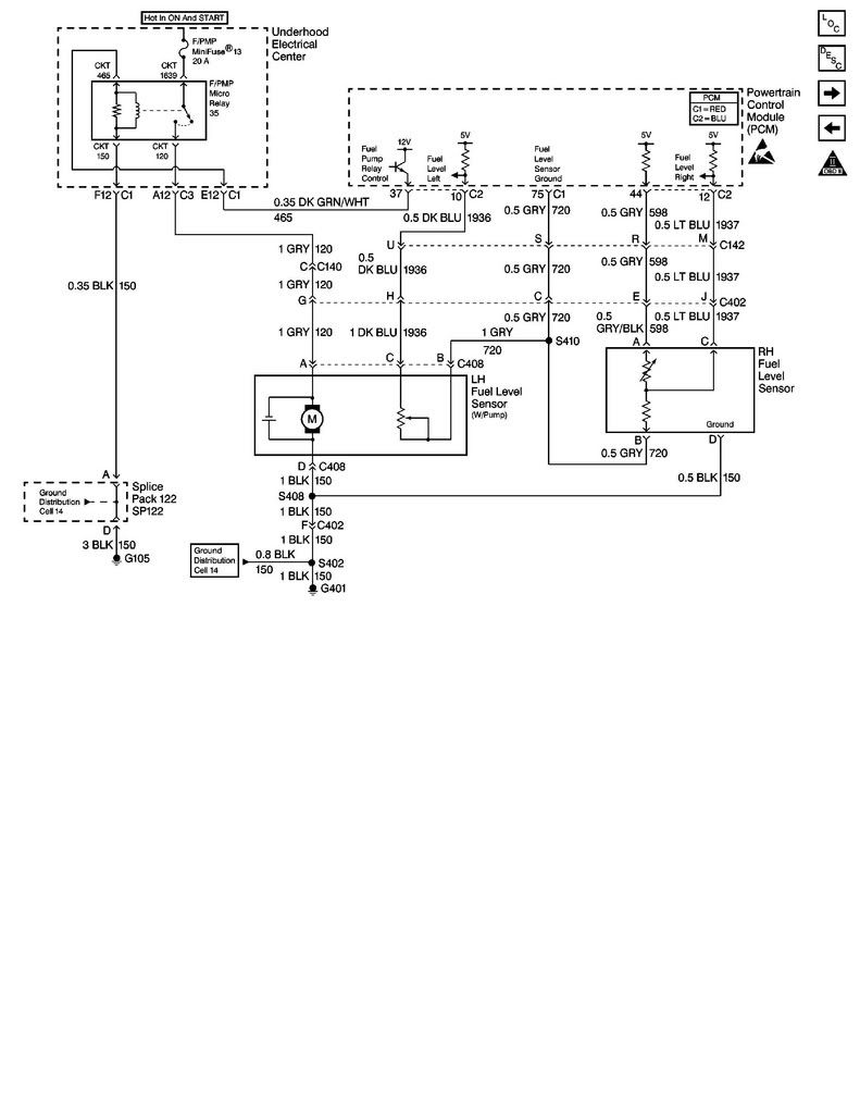
Heres the 97 to 03 sender/pump schematic:

Advanced
Joined: Jul 2011
Posts: 93
Likes: 0
Sounds like the sender or wiring. A clogged jet pump normally sets code P1431.
Other symptoms of a clogged jet pump:
Starting from full, gauge goes to zero after a couple of hundred highway miles. This is when the PCM senses improper level between tanks.
If you keep going and run out of gas, the car will only take about 12 gallons or so.
Other symptoms of a clogged jet pump:
Starting from full, gauge goes to zero after a couple of hundred highway miles. This is when the PCM senses improper level between tanks.
If you keep going and run out of gas, the car will only take about 12 gallons or so.
Team Owner
Joined: May 2001
Posts: 36,836
Likes: 244
From: Dear Karma, I have a list of people you missed.
St. Jude Donor '08-'09-'10-'11-'12-'13-'14-'15-'16
Btw, the "sender" for the right side is not available as a separate item, only the driver's side.
Advanced
Joined: Jul 2011
Posts: 93
Likes: 0
What other symptoms are you experiencing???? For example if you let the tanks get below half to say 1/3, do you add more than 8 gallons to fill the tanks or less than 8?
Could be just a build up of oxidation on the sensors or it might be that the jet syphon pump is not operating. More info about your symptoms can help narrow that down.
Could be just a build up of oxidation on the sensors or it might be that the jet syphon pump is not operating. More info about your symptoms can help narrow that down.
Thread Starter
Instructor
Joined: Nov 2006
Posts: 233
Likes: 2
The strangest thing... Now, after replacing the sensor and entire right side assembly, it works fine except somewhere around 5/8 of a tank it decides to drop to 0 for an hour or two of driving, then it somehow decides to start working again. It then goes back up to somewhere just above 1/2 tank and continues to work throughout the rest of the fuel gauge's range. I think it's also giving me a 1431. I can live with this problem, and I don't have any plans to change anything for the time being unless it gets worse or a solution becomes obvious.
Advanced
Joined: Jul 2011
Posts: 93
Likes: 0
What other symptoms are you experiencing???? For example if you let the tanks get below half to say 1/3, do you add more than 8 gallons to fill the tanks or less than 8?
Could be just a build up of oxidation on the sensors or it might be that the jet syphon pump is not operating. More info about your symptoms can help narrow that down.
Could be just a build up of oxidation on the sensors or it might be that the jet syphon pump is not operating. More info about your symptoms can help narrow that down.