


Help requested with one-wire bus failure

Thread Starter
Racer


Joined: Oct 2011
Posts: 265
Likes: 5
I could use some help. My 02Z has been having intermittent problems with its one-wire bus, causing the appearance of a multi-system failure (traction control, service engine, no fuel, etc.). The problem comes and goes, somewhat correlating with ambient temperatures but not consistently so. I haven't figured out why it sometimes fails and sometimes works or how the weather seems to be affecting it.
I checked and cleaned the star connectors in the passenger foot well area, but this didn't help. I cleaned the connection in the passenger door connector, and this seemed to help for a while. When I looked at the driver's door connector, I saw that the pins were angled slightly inward for a surer connection, so I did the same to the passenger door connector pins. This helps for several days. Yay! But...the problem is back. I've checked many of the chassis grounds (the ones I can reasonably reach without much fuss--I may need to endure some fuss, though) and look reasonable. The battery has been replaced, so it's not a low-voltage issue; unrelated to this problem, my old battery was not getting above 12V so it needed replacement anyway. The only thing of which I am aware that I haven't checked are the seat connectors. (Do I need to remove the seats to access and/or isolate these?)
Have I missed anything? I've searched CF quite a bit on this issue, which is how I learned of the above things to check and clean. Is there more that I've missed? I still need to drag out the manuals and see where that bus goes, but the codes (several Uxxxx codes, plus "no comm" to PCM) suggest it goes all over the place. I'd certainly appreciate any help you guys can offer, especially if your experience suggests a troublesome spot I haven't yet checked.

Tech Contributor


Joined: Dec 1999
Posts: 32,910
Likes: 2,402
From: Anthony TX
CI 6,7,8,9,11 Vet
St. Jude Donor '08
If it were me,, I would pull the STAR Connector top (the one with four wires for the LDCM, RDCM and SCM) and leave it disconnected to see if the issues goes away. You can reach the seat connector if you raise the seat all the way up.
The seat connector often gets damaged because it the low hanging fruit under the seat.
 It can and does cause issues on the data buss.
If I were you I would also consider cleaning or replacing your ignition switch. That will eliminate any low voltage issues on the IGNITION POWERED circuits.
-C5 ignition Switch repair - http://forums.corvetteforum.com/c5-t...ch-repair.html
BC
The seat connector often gets damaged because it the low hanging fruit under the seat.
It can and does cause issues on the data buss.If I were you I would also consider cleaning or replacing your ignition switch. That will eliminate any low voltage issues on the IGNITION POWERED circuits.
-C5 ignition Switch repair - http://forums.corvetteforum.com/c5-t...ch-repair.html
BC
Thread Starter
Racer
Joined: Oct 2011
Posts: 265
Likes: 5
Well, it's not the four-wire star connector or its subsystems. It's not the seat connector either.
I've narrowed the relevant codes to:
PCM No Comm.
TCS U1000
BCM U1255
SDM U1000, U1016
RFA U1000
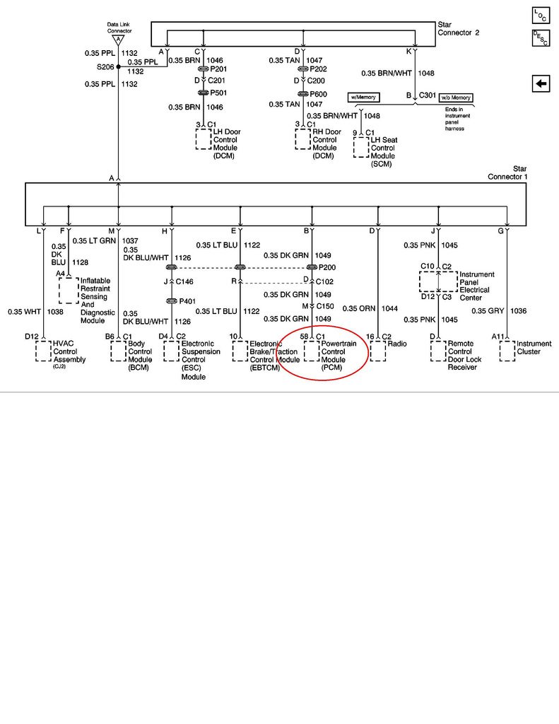
These seem to be pretty much PCM-centric, so I'll concentrate my efforts there. Looking at the DLC schematic, the PCM is pin B, dark green. Maybe in my earlier attempts to isolate it to the right door connector, I may have inadvertently mangled the PCM's connection to the DLC.
I've narrowed the relevant codes to:
PCM No Comm.
TCS U1000
BCM U1255
SDM U1000, U1016
RFA U1000
These seem to be pretty much PCM-centric, so I'll concentrate my efforts there. Looking at the DLC schematic, the PCM is pin B, dark green. Maybe in my earlier attempts to isolate it to the right door connector, I may have inadvertently mangled the PCM's connection to the DLC.
Tech Contributor


Joined: Jan 2007
Posts: 19,465
Likes: 1,167
From: Dyer, IN
The PCM connects directly to star connector #1.....not the DLC.
Thread Starter
Racer
Joined: Oct 2011
Posts: 265
Likes: 5
That's what I meant. Perhaps I'm using the term DLC incorrectly. I associated "DLC" with the one-wire bus and therefore the star connectors as if these were all functionally synonymous. I welcome correction, though, as I'm still learning lots (for which I am very grateful to CF and its abundantly helpful members).
Tech Contributor
Joined: Jan 2007
Posts: 19,465
Likes: 1,167
From: Dyer, IN
That's what I meant. Perhaps I'm using the term DLC incorrectly. I associated "DLC" with the one-wire bus and therefore the star connectors as if these were all functionally synonymous. I welcome correction, though, as I'm still learning lots (for which I am very grateful to CF and its abundantly helpful members).
Last edited by lucky131969; Oct 19, 2012 at 05:56 PM.
Corvette Stories
The Best of Corvette for Corvette Enthusiasts

Top 10 Most Expensive Corvettes Ever Sold on Bring A Trailer
Brett Foote
10 Things Every Corvette Owner Needs (2026 Edition)
Michael S. Palmer
8 Most "Only Corvette Owners Understand" Quirks and Problems
Pouria Savadkouei
10 Reasons the C6 Z06 is Still A Performance Benchmark After 20 Years
Joe Kucinski
How Much Horsepower Every Corvette Engine "LOST" in 1972
Joe Kucinski
Top 10 DOs and DON'Ts for Protecting Your Convertible Top!
Michael S. Palmer
Top 10 Most Explosive Corvettes Ever Made: Power-to-Weight Ratio Ranked!
Joe Kucinski
150 hp to 1,250 hp: Every Corvette Generation Compared by the Specs That Matter
Joe Kucinski
8 Coolest Corvette Pace Cars (and Replicas) of All Time
Verdad Gallardo
Tech Contributor
Joined: Dec 1999
Posts: 32,910
Likes: 2,402
From: Anthony TX
CI 6,7,8,9,11 Vet
St. Jude Donor '08
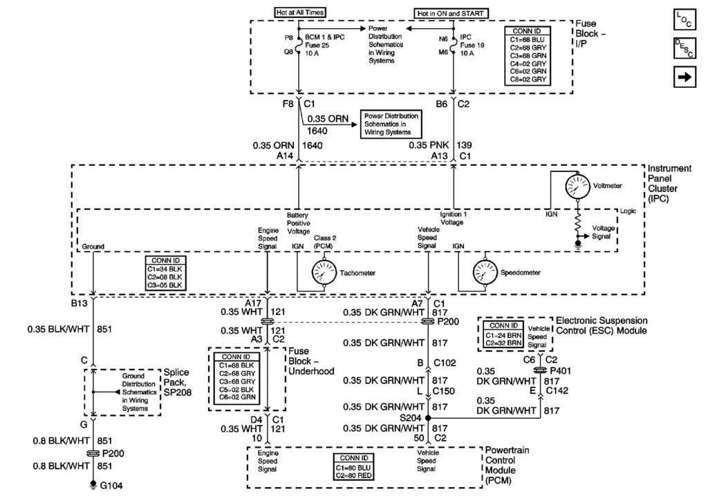
Here are the schematics that you need to see how everything works. Some of the gages and functions on the IPC are imulated and are digital signals transmitted over the DATA BUSS
Last edited by Bill Curlee; Oct 19, 2012 at 05:56 PM.
Tech Contributor
Joined: Dec 1999
Posts: 32,910
Likes: 2,402
From: Anthony TX
CI 6,7,8,9,11 Vet
St. Jude Donor '08
Read this post and do the same.. Read the resistance of each module and post here.
http://forums.corvetteforum.com/c5-t...on-on-dtc.html
BC
http://forums.corvetteforum.com/c5-t...on-on-dtc.html
BC
Thread Starter
Racer
Joined: Oct 2011
Posts: 265
Likes: 5
Read this post and do the same.. Read the resistance of each module and post here.
http://forums.corvetteforum.com/c5-t...on-on-dtc.html
BC
http://forums.corvetteforum.com/c5-t...on-on-dtc.html
BC
Tech Contributor
Joined: Dec 1999
Posts: 32,910
Likes: 2,402
From: Anthony TX
CI 6,7,8,9,11 Vet
St. Jude Donor '08
Well............. If you find a reading out of line with the norm,, disconnect that module at the module and read the wire from the STAR connector to the connector and then read the disconnect module buss pin to the ground pin on the module. The LOW reading will be apparent where its at.
BC
BC
Thread Starter
Racer
Joined: Oct 2011
Posts: 265
Likes: 5
That sounds reasonable.
As part of my diags today, I checked continuity from the star connector to the PCM's connector (pin 58 on blue). Looked fine. I even went so far as to open up the PCM on the off chance I could see a blown component, but it looked good, and continuity from its connector through its initial, internal RC was good. Given the IPC-BCM-PCM isolation and the PCM-centric codes, plus the good continuity outside and just into the PCM, I surmised the problem probably lies within silicon in the PCM. I expect a resistance-to-ground test will likely confirm this.
As part of my diags today, I checked continuity from the star connector to the PCM's connector (pin 58 on blue). Looked fine. I even went so far as to open up the PCM on the off chance I could see a blown component, but it looked good, and continuity from its connector through its initial, internal RC was good. Given the IPC-BCM-PCM isolation and the PCM-centric codes, plus the good continuity outside and just into the PCM, I surmised the problem probably lies within silicon in the PCM. I expect a resistance-to-ground test will likely confirm this.
Thread Starter
Racer
Joined: Oct 2011
Posts: 265
Likes: 5
I can't believe this, but all the symptoms have returned, even with a new PCM. I'm turning it over to the pros but will post the final resolution (after it's worked for many days without issue) for others who might encounter these symptoms in the future.
Tech Contributor
Joined: Dec 1999
Posts: 32,910
Likes: 2,402
From: Anthony TX
CI 6,7,8,9,11 Vet
St. Jude Donor '08
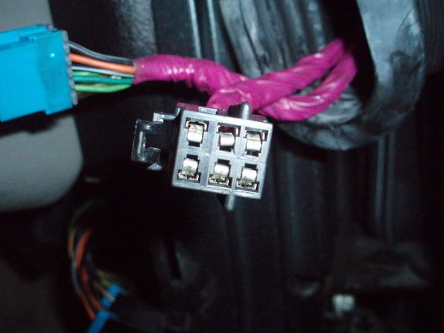
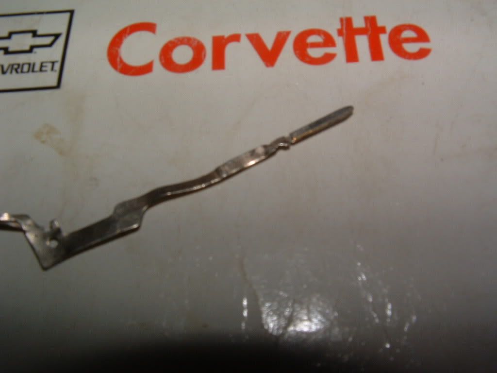
Well,,,, If your NOT looking very closely at any and all FEMALE PINS in the data buss circuit and door power plug, your doing your self a disservice. Shop time will get VERY expensive with an intermittant issue.
Recheck your door power connector and make sure ALL the female pins are not spread apart. You really need to fins spare male pins and insert the male pin into any female pin that is in the circuits that need to be checked...
Use a male pin of the correct size and CHECK THOSE FAMELE PINS!
Recheck your door power connector and make sure ALL the female pins are not spread apart. You really need to fins spare male pins and insert the male pin into any female pin that is in the circuits that need to be checked...
Use a male pin of the correct size and CHECK THOSE FAMELE PINS!