


Need Help with Reduced Power Problems

Thread Starter
Cruising

Joined: Jun 2012
Posts: 10
Likes: 0
From: Trenton NJ
2002 Corvette Coupe, no mods other than air filter.
The problem started the other day on the highway. Cruising at 70 the car throws up the Reduced Power/ Service TCS on the DIC. Car wouldn't go over 50, so pulled over shut it off and restarted. It came back on fine but within 10 minutes did the same thing.
Got home, cleared the codes and it seemed fine. Then after 5 minutes it did the TCS service again. The codes it gave immediately after that were:
P1220,P1221, C1278,B0446,B0017.
I have seen a bunch of threads about this same type of problem but with different codes and not many solutions or answers. I saw one guy said it happened after he washed his but went away in a day. The car did go through the carwash earlier in the day that this first happened but it has been days since it has gotten wet and it seems like it would have dried out by now if it was a moisture problem.
Definitely at a loss here. Any help or direction would be greatly appreciated. Don't want to spend hundreds on a dealer/mechanic right now if this is a possible easy DIY.
Thanks.

Tech Contributor


Joined: Dec 1999
Posts: 32,910
Likes: 2,402
From: Anthony TX
CI 6,7,8,9,11 Vet
St. Jude Donor '08
Looks like you need to examine the Throttle Position Sensor. Have you ever washed your engine or sprayed the TB with any liquids?? Replace it with a new one. You can get one from the autoparts store.
DTC P1220
Circuit Description
The throttle position (TP) sensor is mounted on the throttle body assembly. The sensor is actually 2 individual TP sensors within 1 housing. Two separate signal, low reference and 5-volt reference circuits are used in order to connect the TP sensor assembly to the throttle actuator control (TAC) module. The 2 sensors have opposite functionality. The TP sensor 1 signal voltage is pulled up to the reference voltage as the throttle opens, from below 1 volt at closed throttle to above 3.5 volts at wide open throttle (WOT). The TP sensor 2 signal voltage is pulled down to the low reference from around 3.8 volts at closed throttle to below 1 volt at WOT. TP sensor 1 and APP sensor 1 share a 5-volt reference circuit that is connected within the TAC module. TP sensor 2 and APP sensor 2 share a 5-volt reference circuit that is connected within the TAC module. If an out of range condition is detected with the TP sensor 2, this DTC will set and the Reduced Engine Power message will be displayed.
Conditions for Running the DTC
DTCs P1517, or P1518 are not set.
The ignition switch in the crank position or run the position.
The ignition voltage is greater than 5.23 volts.
Conditions for Setting the DTC
The TP sensor 2 voltage is less than 0.13 volts or greater than 4.87 volts.
All above conditions present for less than 1 second.
Action Taken When the DTC Sets
The control module illuminates the malfunction indicator lamp (MIL) when the diagnostic runs and fails.
The control module records the operating conditions at the time the diagnostic fails. The control module stores this information in the Freeze Frame and/or the Failure Records.
The control module commands the TAC system to operate in the Reduced Engine Power mode.
A message center or an indicator displays Reduced Engine Power.
Under certain conditions the control module commands the engine OFF.
Conditions for Clearing the MIL/DTC
The control module turns OFF the malfunction indicator lamp (MIL) after 3 consecutive ignition cycles that the diagnostic runs and does not fail.
A current DTC, Last Test Failed, clears when the diagnostic runs and passes.
A history DTC clears after 40 consecutive warm-up cycles, if no failures are reported by this or any other emission related diagnostic.
Clear the MIL and the DTC with a scan tool.
Diagnostic Aids
Inspect the throttle actuator control (TAC) module connectors for signs of water intrusion. When water intrusion occurs, multiple DTCs could be set with no DTC circuit or component conditions found during diagnostic testing.
When the TAC module detects a condition within the TAC System, more than one TAC System related DTC may set. This is due to the many redundant tests run continuously on this system. Locating and repairing one individual condition may correct more than one DTC. Disconnecting components during testing may set additional DTCs. Keep this in mind when reviewing the stored information, Capture info.
If this DTC is determined to be intermittent, refer to Intermittent Conditions .
Test Description
The numbers below refer to the step numbers on the diagnostic table.
Using a test lamp reduces the amount of current fed into the signal circuit. The scan tool should display the maximum value for this parameter, 5-volts even though the actual voltage is higher.
The TP 2 sensor and the APP 2 sensor share a common 5 volt reference. The 5-volt reference circuits are connected internally within the TAC module. Disconnecting the TAC module will isolate the 5-volt reference circuits.
The TP sensor 2 and the APP sensor 2 share a common 5-volt reference. A short to voltage on the APP sensor 2, 5-volt reference circuit will affect the TP sensor 2, 5-volt reference circuit.
When the TAC module detects a condition within the TAC system, more than 1 TAC system related DTC may set. This condition is due to the many redundant tests that run continuously on this system. Locating and repairing 1 individual condition may correct more than 1 DTC. Disconnecting components during testing may set additional DTCs. Keep this in mind when reviewing the stored information, Capture info.
DTC P1220 - Throttle Position (TP) Sensor 2 Circuit Step
Action
Values
Yes
No
Schematic Reference: Engine Controls Schematics
1
Did you perform the Diagnostic System Check-Engine Controls?
--
Go to Step 2
Go to Diagnostic System Check - Engine Controls
2
Is DTC P1515, P1516, or P1518 also set?
--
Go to Diagnostic Trouble Code (DTC) List
Go to Step 3
3
Turn OFF the ignition.
Remove the air inlet duct from the throttle body assembly.
Disconnect the throttle actuator motor harness connector.
Turn ON the ignition, with the engine OFF.
Manually close the throttle blade completely while observing the TP sensor 2 voltage parameter on the scan tool.
Does the scan tool indicate that the TP sensor 2 voltage is within the specified values?
4.3-4.8 V
Go to Step 4
Go to Step 7
4
Open the throttle blade to wide open throttle (WOT) by hand while observing the TP sensor 2 voltage parameter on the scan tool.
Does the scan tool indicate TP sensor 2 voltage within the specified values?
0.13-1 V
Go to Step 5
Go to Step 7
5
Turn OFF the ignition for 15 seconds.
Reconnect the throttle actuator motor harness connector.
Reinstall the air inlet duct.
Turn ON the ignition with the engine OFF.
Select the DTC Info. option on the scan tool.
Lightly touch and move the related engine wiring harnesses and connectors for the TP sensor while observing the DTC Info. The DTC will set if an intermittent condition is present. Refer to Testing for Intermittent and Poor Connections and Wiring Repairs in Wiring Systems.
Did you find and correct the condition?
--
Go to Step 35
Go to Step 6
6
Continue to observe DTC Info.
Slowly depress the accelerator pedal to WOT and then slowly return the pedal to the released position 3 times.
Does the scan tool indicate this DTC failed this ignition?
--
Go to Step 26
Go to Diagnostic Aids
7
With a scan tool, observe the TP sensor 2 voltage parameter.
Does the scan tool indicate that the TP sensor 2 voltage is at the specified value?
5 V
Go to Step 8
Go to Step 12
8
Disconnect the TP sensor harness connector.
Does the scan tool indicate that the TP sensor 2 voltage is at the specified value?
0 V
Go to Step 9
Go to Step 13
9
Disconnect the APP sensor harness connector.
Turn ON the ignition with the engine OFF.
With a DMM, test the TP sensor 2, 5-volt reference circuit for voltage.
Does the DMM indicate voltage near the specified value?
5 V
Go to Step 10
Go to Step 18
10
With a DMM connected between the TP sensor 1 low reference circuit and the TP sensor 2 low reference circuit at the TP sensor harness connector, test for resistance
Does the DMM indicate resistance within the specified values?
0-5 ohms
Go to Step 14
Go to Step 11
11
Turn OFF the ignition.
Disconnect the TAC module harness connector containing the TP sensor circuits.
With a DMM, test the TP sensor 2 low reference circuit for an open or for high resistance. Refer to Circuit Testing and Wiring Repairs in Wiring Systems.
Did you find and correct the condition?
--
Go to Step 35
Go to Step 32
12
Disconnect the TP sensor harness connector.
Connect a test lamp between the TP sensor 2 signal circuit and the battery positive voltage.
Does the scan tool indicate TP sensor 2 voltage near the specified value?
5 V
Go to Step 20
Go to Step 15
13
Turn OFF the ignition.
Disconnect the TAC module harness connector containing the TP sensor circuits.
Turn ON the ignition.
With a DMM, test the TP sensor 2 signal circuit for a short to voltage. Refer to Circuit Testing and Wiring Repairs in Wiring Systems.
Did you find and correct the condition?
--
Go to Step 35
Go to Step 17
14
Turn OFF the ignition.
Disconnect the TAC module harness connector containing the APP sensor circuits.
Turn ON the ignition with the engine OFF.
With a DMM, test the APP sensor 2 signal circuit for a short to voltage. Refer to Circuit Testing and Wiring Repairs in Wiring Systems.
Did you find and correct the condition?
--
Go to Step 35
Go to Step 24
15
Turn OFF the ignition.
Disconnect the TAC module harness connector containing the TP sensor circuits.
With a DMM, test the TP sensor 2 signal circuit for an open or for high resistance. Refer to Circuit Testing and Wiring Repairs in Wiring Systems.
Did you find and correct the condition?
--
Go to Step 35
Go to Step 16
16
With a DMM, test the TP sensor 2 signal circuit for a short to ground. Refer to Circuit Testing and Wiring Repairs in Wiring Systems.
Did you find and correct the condition?
--
Go to Step 35
Go to Step 17
17
With a DMM, test for a short between the TP sensor 2 signal circuit and all other TAC module circuits. Refer to Circuit Testing and Wiring Repairs in Wiring Systems.
Did you find and correct the condition?
--
Go to Step 35
Go to Step 32
18
Turn OFF the ignition.
Disconnect the TAC module harness connector containing the TP sensor circuits.
Turn ON the ignition with the engine OFF.
With a DMM, test the TP sensor 2, 5-volt reference circuit for a short to voltage. Refer to Circuit Testing and Wiring Repairs in Wiring Systems.
Did you find and correct the condition?
--
Go to Step 35
Go to Step 19
19
Turn OFF the ignition.
Disconnect the other TAC module harness connector.
Turn ON the ignition with the engine OFF.
With a DMM, test the APP sensor 2 5-volt reference circuit for a short to voltage. Refer to Circuit Testing and Wiring Repairs in Wiring Systems.
Did you find and correct the condition?
--
Go to Step 35
Go to Step 24
20
Turn OFF the ignition.
Disconnect the TAC module harness connector containing the TP sensor circuits.
With a DMM, test the TP sensor 2 5-volt reference circuit for an open or for high resistance. Refer to Circuit Testing and Wiring Repairs in Wiring Systems.
Did you find and correct the condition?
--
Go to Step 35
Go to Step 21
21
With a DMM, test the TP sensor 2 5-volt reference circuit for a short to ground. Refer to Circuit Testing and Wiring Repairs in Wiring Systems.
Did you find and correct the condition?
--
Go to Step 35
Go to Step 22
22
Disconnect the APP sensor harness connector.
Disconnect the other TAC module harness connector.
Turn ON the ignition with the engine OFF.
With a DMM, test the APP sensor 2 signal circuit for a short to voltage. Refer to Circuit Testing and Wiring Repairs in Wiring Systems.
Did you find and correct the condition?
--
Go to Step 35
Go to Step 23
23
With a DMM, test the APP sensor 2 5-volt reference circuit for a short to ground. Refer to Circuit Testing and Wiring Repairs in Wiring Systems.
Did you find and correct the condition?
--
Go to Step 35
Go to Step 24
24
With a DMM, test the TP sensor 2 5-volt reference circuit for a short to voltage. Refer to Circuit Testing and Wiring Repairs in Wiring Systems.
Did you find and correct the condition?
--
Go to Step 35
Go to Step 25
25
With a DMM, test for a short between the TP sensor 2 5-volt reference circuit and all other TAC module circuits. Refer to Circuit Testing and Wiring Repairs in Wiring Systems.
Did you find and correct the condition?
--
Go to Step 35
Go to Step 26
26
With a DMM, test for a short between the APP sensor 2 5-volt reference circuit and all other TAC module circuits. Refer to Circuit Testing and Wiring Repairs in Wiring Systems.
Did you find and correct the condition?
--
Go to Step 35
Go to Step 27
27
With a DMM, test the TP sensor 2 signal circuit for high resistance. Refer to Circuit Testing and Wiring Repairs in Wiring Systems.
Did you find and correct the condition?
--
Go to Step 35
Go to Step 28
28
With a DMM, test the TP sensor 2 low reference circuit for resistance. Refer to Circuit Testing and Wiring Repairs in Wiring Systems.
Did you find and correct the condition?
--
Go to Step 35
Go to Step 29
29
Reconnect the TAC module connectors.
Turn ON the ignition.
With a DMM, measure voltage at the TP sensor 2, 5-volt reference circuit.
Does the DMM indicate voltage greater than the specified value?
6.06 V
Go to Step 32
Go to Step 30
30
Turn OFF the ignition.
Connect a test lamp between APP sensor 2, 5-volt reference and battery positive voltage.
Does the test lamp illuminate?
--
Go to Step 32
Go to Step 31
31
Inspect for poor connections at the TP sensor harness connector. Refer to Testing for Intermittent and Poor Connections and Repairing Connector Terminals in Wiring Systems.
Did you find and correct the condition?
--
Go to Step 35
Go to Step 33
32
Inspect for poor connections at the TAC module harness connector. Refer to Testing for Intermittent and Poor Connections and Repairing Connector Terminals in Wiring Systems.
Did you find and correct the condition?
--
Go to Step 35
Go to Step 34
33
Important
The throttle position sensor is not a serviceable part and should only be replaced with the throttle body assembly.
Replace the throttle body assembly. Refer to Throttle Body Assembly Replacement .
Did you complete the replacement?
--
Go to Step 35
--
34
Replace the TAC module. Refer to Throttle Actuator Control (TAC) Module Replacement .
Did you complete the replacement?
--
Go to Step 35
--
35
Clear the DTCs with a scan tool.
Turn OFF the ignition for 30 seconds.
Start the engine.
Operate the vehicle within the Conditions for Running the DTC as specified in the supporting text.
Does the DTC run and pass?
--
Go to Step 36
Go to Step 2
36
With a scan tool, observe the stored information, Capture Info.
Does the scan tool indicate any DTCs that you have not diagnosed?
--
Go to Diagnostic Trouble Code (DTC) List
System OK
--------------------------------------------------------------------------------
Document ID# 706248
2002 Chevrolet Corvette
======================================== ============================
Document ID# 706250
2002 Chevrolet Corvette
--------------------------------------------------------------------------------
DTC P1221
Circuit Description
The throttle position (TP) sensor is mounted on the throttle body assembly. The sensor is actually 2 individual TP sensors within 1 housing. Two separate signal, low reference and 5 volt reference circuits are used in order to connect the TP sensor assembly to the throttle actuator control (TAC) module. The 2 sensors have opposite functionality. The TP sensor 1 signal voltage is pulled up to the reference voltage as the throttle opens, from below 1 volt at closed throttle to above 3.5 volts at wide open throttle (WOT). The TP sensor 2 signal voltage is pulled down to the low reference from around 3.8 volts at closed throttle to below 1 volt at WOT. TP sensor 1 and APP sensor 1 share a 5-volt reference circuit that is connected within the TAC module. TP sensor 2 and APP sensor 2 share a 5-volt reference circuit that is connected within the TAC module. If an out of range condition is detected with the TP sensors, this DTC will set and the Reduced Engine Power message will be displayed.
Conditions for Running the DTC
DTCs P1517, or P1518 are not set.
The ignition switch is in the crank or run position.
The ignition voltage is greater than 5.23 volts.
Conditions for Setting the DTC
TP sensor 2 disagrees with TP sensor 1 by more than 7.5 percent.
All above conditions are present for less than 1 second.
Action Taken When the DTC Sets
The control module illuminates the malfunction indicator lamp (MIL) when the diagnostic runs and fails.
The control module records the operating conditions at the time the diagnostic fails. The control module stores this information in the Freeze Frame and/or the Failure Records.
The control module commands the TAC system to operate in the Reduced Engine Power mode.
A message center or an indicator displays Reduced Engine Power.
Under certain conditions the control module commands the engine OFF.
Conditions for Clearing the MIL/DTC
The control module turns OFF the malfunction indicator lamp (MIL) after 3 consecutive ignition cycles that the diagnostic runs and does not fail.
A current DTC, Last Test Failed, clears when the diagnostic runs and passes.
A history DTC clears after 40 consecutive warm-up cycles, if no failures are reported by this or any other emission related diagnostic.
Clear the MIL and the DTC with a scan tool.
Diagnostic Aids
Inspect the TAC module connectors for signs of water intrusion. When water intrusion occurs, multiple DTCs could be set with no DTC circuit or component conditions found during diagnostic testing.
When the TAC module detects a condition within the TAC system, more than 1 TAC system related DTC may set. This is due to the many redundant tests that run continuously on this system. Locating and repairing 1 individual condition may correct more than 1 DTC. Disconnecting components during testing may set additional DTCs. Keep this in mind when reviewing the stored information, Capture info.
If this DTC is determined to be intermittent, refer to Intermittent Conditions .
Test Description
The numbers below refer to the step numbers on the diagnostic table.
When the TAC module detects a condition within the TAC system, more than 1 TAC system related DTC may set. This is due to the many redundant tests that run continuously on this system. Locating and repairing 1 individual condition may correct more than 1 DTC. Disconnecting components during testing may set additional DTCs. Keep this in mind when reviewing the stored information, Capture info.
DTC P1221 - Throttle Position (TP) Sensors 1, 2 Performance Step
Action
Yes
No
Schematic Reference: Engine Controls Schematics
1
Did you perform the Diagnostic System Check-Engine Controls?
Go to Step 2
Go to Diagnostic System Check - Engine Controls
2
Is DTC P1518 also set?
Go to Diagnostic Trouble Code (DTC) List
Go to Step 3
3
Turn ON the ignition, with the engine OFF.
With a scan tool, observe the TP sensor 1 and 2 Agree/Disagree parameter.
Does the scan tool TP sensor 1 and 2 Agree/Disagree parameter indicate Disagree?
Go to Step 5
Go to Step 4
4
Remove the air inlet duct from the throttle body.
Disconnect the throttle actuator motor harness connector.
Slowly manually open the throttle blade to WOT and back to the closed throttle position several times while observing the scan tool TP sensor Agree/Disagree parameter.
Does the TP sensor Agree/Disagree parameter change from Agree to Disagree during the above test?
Go to Step 18
Go to Step 5
5
Disconnect the TP sensor harness connector.
Disconnect the TAC module harness connectors.
Test the TP sensor 1 5-volt reference circuit for resistance. Refer to Circuit Testing and Wiring Repairs in Wiring Systems.
Did you find and correct the condition?
Go to Step 20
Go to Step 6
6
With a DMM, test for a short between the TP sensor 1 5-volt reference circuit and all other TAC module circuits. Refer to Circuit Testing and Wiring Repairs in Wiring Systems.
Did you find and correct the condition?
Go to Step 20
Go to Step 7
7
With a DMM, test the TP sensor 1 signal circuit for resistance. Refer to Circuit Testing and Wiring Repairs in Wiring Systems.
Did you find and correct the condition?
Go to Step 20
Go to Step 8
8
With a DMM, test for a short between the TP sensor 1 signal circuit and all other TAC module circuits. Refer to Circuit Testing and Wiring Repairs in Wiring Systems.
Did you find and correct the condition?
Go to Step 20
Go to Step 9
9
With a DMM, test the TP sensor 1 low reference circuit for resistance. Refer to Circuit Testing and Wiring Repairs in Wiring Systems.
Did you find and correct the condition?
Go to Step 20
Go to Step 10
10
With a DMM, test for a short between the TP sensor 1 low reference circuit and all other TAC module circuits. Refer to Circuit Testing and Wiring Repairs in Wiring Systems.
Did you find and correct the condition?
Go to Step 20
Go to Step 11
11
With a DMM, test the TP sensor 2 5-volt reference circuit for resistance. Refer to Circuit Testing and Wiring Repairs in Wiring Systems.
Did you find and correct the condition?
Go to Step 20
Go to Step 12
12
With a DMM, test for a short between the TP sensor 2 5-volt reference circuit and all other TAC module circuits. Refer to Circuit Testing and Wiring Repairs in Wiring Systems.
Did you find and correct the condition?
Go to Step 20
Go to Step 13
13
With a DMM, test the TP sensor 2 signal circuit for resistance. Refer to Circuit Testing and Wiring Repairs in Wiring Systems.
Did you find and correct the condition?
Go to Step 20
Go to Step 14
14
With a DMM, test for a short between the TP sensor 2 signal circuit and all other TAC module circuits. Refer to Circuit Testing and Wiring Repairs in Wiring Systems.
Did you find and correct the condition?
Go to Step 20
Go to Step 15
15
With a DMM, test the TP sensor 2 low reference circuit for resistance. Refer to Circuit Testing and Wiring Repairs in Wiring Systems.
Did you find and correct the condition?
Go to Step 20
Go to Step 16
16
With a DMM, test for a short between the TP sensor 2 low reference circuit and all other TAC module circuits. Refer to Circuit Testing and Wiring Repairs in Wiring Systems.
Did you find and correct the condition?
Go to Step 20
Go to Step 17
17
Inspect for poor connections at the harness connector of the TAC module. Refer to Testing for Intermittent and Poor Connections and Repairing Connector Terminals in Wiring Systems.
Did you find and correct the condition?
Go to Step 20
Go to Step 18
18
Inspect for poor connections at the harness connector of the TP sensor. Refer to Testing for Intermittent and Poor Connections and Repairing Connector Terminals in Wiring Systems.
Did you find and correct the condition?
Go to Step 20
Go to Step 19
19
Important
The throttle position sensor is not a serviceable part and should only be replaced with the throttle body assembly.
Replace the throttle body assembly. Refer to Throttle Body Assembly Replacement .
Did you complete the replacement?
Go to Step 20
--
20
Use a scan tool in order to clear the DTCs.
Turn OFF the ignition for 30 seconds.
Start the engine.
Operate the vehicle within the Conditions for Running the DTC as specified in the supporting text.
Does the DTC run and pass?
Go to Step 21
Go to Step 2
21
With a scan tool, observe the stored information, Capture Info.
Does the scan tool display any DTCs that you have not diagnosed?
Go to Diagnostic Trouble Code (DTC) List
System OK
--------------------------------------------------------------------------------
Document ID# 706250
2002 Chevrolet Corvette

Racer
Joined: Jun 2012
Posts: 288
Likes: 0
Bill helped me out when I had my issue with reduced power. Mine was severe..only clearing up when I replaced and built my own wire harness. Your's as bill said seems to be the tps sensor. Only about $65 at AUTOZONE! NOT advance..they dont carry it. And make SURE you match it up with the one they are selling. Mine being a 2000 was listed as one part, at only $38 or so, when in reality it was another part from a newer year or something like that..it cost me $65 or so. I returned it though after I did the harness as I no longer needed it. EASY to find out and make sure you get the right one. Different wire count on the harness! LOL Just be careful otherwise you will order the wrong darn part!
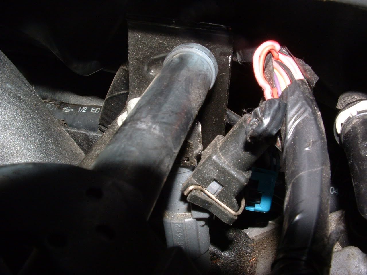
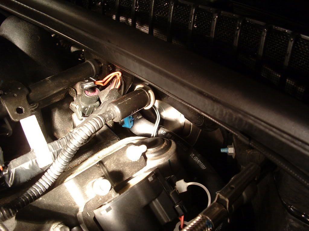
One more thing, if you have a ddm you can easily check the tps you have now. And one last thing...PM bill or ask that he post up the pics showing the metal bracket that always seems to wear into the harness. Likely NOT your issue, but better safe now at relocating the darn thing then waiting till later and it maybe tearing into your harness!
One more thing, if you have a ddm you can easily check the tps you have now. And one last thing...PM bill or ask that he post up the pics showing the metal bracket that always seems to wear into the harness. Likely NOT your issue, but better safe now at relocating the darn thing then waiting till later and it maybe tearing into your harness!
Tech Contributor
Joined: Dec 1999
Posts: 32,910
Likes: 2,402
From: Anthony TX
CI 6,7,8,9,11 Vet
St. Jude Donor '08
That bracket is a fuel rail safety bracket (keeps the fuel rail from breaking off in a crash) and its at the back of the drivers side fuel rail.. If the harness is resting on it, it will cut the wires and cause all sorts of engine electrical issues.

Last edited by Bill Curlee; Nov 25, 2012 at 10:06 AM.

Pro


Joined: Jan 2003
Posts: 638
Likes: 23
From: St. Johns Fl
Please post up your findings. I just started chasing this same problem. I did a search and found several post on this but hardly any of the postings told what they found. I already replace my TPS and it did not help.

7th Gear
Joined: Jun 2012
Posts: 7
Likes: 0
My 2000 c5 did the same thing. After replacing many components with no cure,I found that something had chewed the insulation on several TAC Module harness wires near the fire wall in the engine bay, under the battery tray. Got a TAC Module Pigtail from EFI Connection 814-566-0946. Part #100-00338, clipped off old wires, soldered on new pigtail, that solved the problem. This is a critical area to check because of battery acid infiltration.
Corvette Stories
The Best of Corvette for Corvette Enthusiasts

Top 10 Most Expensive Corvettes Ever Sold on Bring A Trailer
Brett Foote
10 Things Every Corvette Owner Needs (2026 Edition)
Michael S. Palmer
8 Most "Only Corvette Owners Understand" Quirks and Problems
Pouria Savadkouei
10 Reasons the C6 Z06 is Still A Performance Benchmark After 20 Years
Joe Kucinski
How Much Horsepower Every Corvette Engine "LOST" in 1972
Joe Kucinski
Top 10 DOs and DON'Ts for Protecting Your Convertible Top!
Michael S. Palmer
Top 10 Most Explosive Corvettes Ever Made: Power-to-Weight Ratio Ranked!
Joe Kucinski
150 hp to 1,250 hp: Every Corvette Generation Compared by the Specs That Matter
Joe Kucinski
8 Coolest Corvette Pace Cars (and Replicas) of All Time
Verdad GallardoLe Mans Master


Joined: Aug 2005
Posts: 5,375
Likes: 328
From: CA.
St. Jude Donor '13-'14-'15
Here is a great site to diagnose codes---Has very detailed technical procedures--- but about 1/4 the way down shows in plain words the most common causes-----( under title "IMPORTANT" in red letters)
http://www.gearchatter.com/viewtopic9458.php
http://www.gearchatter.com/viewtopic9458.php
Last edited by tblu92; Dec 2, 2012 at 02:52 PM.