


Gremlin King Defeated....I think. (Long)
Thread Starter
Racer


Joined: Aug 2002
Posts: 369
Likes: 11
From: NV
Sorry been so long........
BCM was cleaned and examined again (heads up to anyone contemplating a visit into the BCM, the aluminum box that houses it will come apart with bending during the opening requiring a repair of the housing....easy, but a pain)
However, my codes are all back. It has not acted up all at once though suggesting maybe the cleaning was partially helpful. The modules are all consistent with what they report, that is, U1016 H, and U1096 H.
Tonight I got under the driver side dash looking to evaluate the DLC(Data Link Connector) as logic suggests a wiring/COM break far upstream. I say that because I have checked and rechecked the grounds. The DLC is not likely, for the following reason. There is about 8 inches of wiring from the DLC before it enters a wrapped harness and the travels across the dash to the BCM area in the passenger footwell. I just refuse to believe that this wrapped harness has suddenly developed a broken wire. No water damage (I live in NEVADA..dry as a bone), the car has never been wet inside and the wiring harnesses remain untouched since March 29, 2001(her birthday).
Given what has been checked I am leaning towards either the BCM or the PCM, with PCM first on my list. Bill and I had discussed this earlier, and we both subscribe to the idea of thinking a problem through instead of just changing out "maybe this, maybe that" and running up a big tab on top of the time. However, at some point, one must admit that he can not narrow the list any further, and a decision must be made. So I ask those of you have followed, please put in your two cents.

Le Mans Master

Joined: Mar 2011
Posts: 6,835
Likes: 302
From: Columbia SC
Talk to Bill about the voltages you got at the splice pack. Having voltages at ~12v sure sounds like a short somewhere. You should be measuring almost 0 volts at that grouning location since it is a short distance back to the battery. I have not researched yet what those locations represent on SP 202 which is the one you actually tested. Wish the manual had that Splice pack connector info instead of having to look at every schematic to see if it has a splice pack involved.
Curious why you would choose PCM over BCM as first choice if you have to replace something? I would think the opposite since you have so many BCM functions affected. In your post you never mentioned whether the car will run, only that you have BCM (interior) related functions going haywire when the car is on.
Curious why you would choose PCM over BCM as first choice if you have to replace something? I would think the opposite since you have so many BCM functions affected. In your post you never mentioned whether the car will run, only that you have BCM (interior) related functions going haywire when the car is on.
Safety Car


Joined: Aug 2011
Posts: 4,449
Likes: 409
From: Portland OR
The DLC is just a tap into the system for getting data in and out. I was having issues with it while data logging during a dragstrip run. I have a bad pin in the connector. As Bill has said, those female connectors suck......
I don't imagine you are using the DLC, correct?
Too bad you couldn't borrow a known good working PCM and BCM to try......
Ron
I don't imagine you are using the DLC, correct?
Too bad you couldn't borrow a known good working PCM and BCM to try......
Ron
Last edited by RonSSNova; Mar 12, 2013 at 01:38 AM.
Thread Starter
Racer
Joined: Aug 2002
Posts: 369
Likes: 11
From: NV
Well, yes, the car does run with all the bells and whistles alarming. Earlier, it would cut in and out briefly(second or two) but that seems to have resolved itself. The engine continues to run quite well for the most part. At that time, Bill felt there was an issue with the VATS and while trouble shooting it we uncovered a few things that may have had to do with it. After cleaning them up that has cleared up. Take a moment and read one of his earlier posts here.......he outlines it.
As for the PCM over BCM .....there is an interesting chart in the service manual (Section- Body and Accessories, Data Link Connectors, Ch.8-173) that describes the method for determining which module is not communicating. Specifically based on DTC U1001-U1254. The last 3 numbers in the DTC identify the module. All of us know that U codes are communication issues, but with this chart one can see from where the issue comes........for instance (based on my two consistent and persistent recurring codes):
U1016-------- U1 016 016 is PCM
U1096-------- U1 096 096 is IPC
SDM, BCM, TCS, RDCM, LDCM, SCM, HVAC, AND BoRfa all show U1016, meaning (and this is where I have trouble, as the manual is not clear) that these modules are not communicating with the PCM. However, several of them also show (U1096) suggesting loss of com with IPC. Occ all of them show both further confusing the picture. However in those that show loss on both PCM and IPC, the IPC itself is showing U1016! So at this point my best guess is that the IPC has the main problem. The above mentioned page in the manual is chock full of helpful tidbits of info that can further help or hinder.........but I invite further discussion.
Thread Starter
Racer
Joined: Aug 2002
Posts: 369
Likes: 11
From: NV
The DLC is just a tap into the system for getting data in and out. I was haing issues with it while data logging during a dragstrip run. I have a bad pin in the connector. As Bill has said, those female connectors suck......
I don't imagine you are using the DLC, correct?
Too bad you couldn't borrow a known good working PCM and BCM to try......
Ron
I don't imagine you are using the DLC, correct?
Too bad you couldn't borrow a known good working PCM and BCM to try......
Ron
Yes, borrowing one of those would be a huge help. As for the DLC, I used it to scan at first, more for confirming than anything else.......but several times the tool would not connect with the car computer.....still not sure as to why as the connector and pins where in very good shape. My concern at that area is that since my issues are hitting modules from BOTH star connectors, I felt the only place I could be having a short or open is at the point before the wiring branches off to the connectors, which seemed close to the DLC though I never saw the branching point as it was buried in wrapped harness.

Tech Contributor


Joined: Dec 1999
Posts: 32,910
Likes: 2,402
From: Anthony TX
CI 6,7,8,9,11 Vet
St. Jude Donor '08
Now that you have cleaned the BCM board, Find the STAR Connector that has FOUR WIRES and remove the top of that connector. With that removed you have the LDCM, RDCM and the Seat Module SERIAL DATA wires isolated from the rest of the modules. It�s a quick way to figure out if any of those module are causing the issue.
Drive it with those modules isolated and see if that changes symptoms. Those modules will indicate NO COMMS while they are isolated.
If that doesn�t change the symptoms, carefully examine the wiring at the PCM and make sure that you don�t have ACID DAMAGE from a past battery leak.
If you don�t have any acid damage, start pulling the other monitored modules one at a time to see if they are corrupting the serial data line.
Modules like HVAC, Radio, SDM etc...........
Thread Starter
Racer
Joined: Aug 2002
Posts: 369
Likes: 11
From: NV
Guys.....take a look at this because I have an issue. My service manual states SP208 as being "RH side of instrument panel". It's not labelled in any drawings and I have had various comments about its location...all different. I submit this service manual drawing to review. The connector on the harness that I think is 208, matches the pins outlined for SP208 exactly. Take a look and give me advice.
I have not yet been able to try Bill's suggestion as when I pulled the front seat to check the SCM I found a broken bracket that needs to be custom made. So for the moment, no seat in the car! What next?
I have not yet been able to try Bill's suggestion as when I pulled the front seat to check the SCM I found a broken bracket that needs to be custom made. So for the moment, no seat in the car! What next?
Corvette Stories
The Best of Corvette for Corvette Enthusiasts

Top 10 Most Expensive Corvettes Ever Sold on Bring A Trailer
Brett Foote
10 Things Every Corvette Owner Needs (2026 Edition)
Michael S. Palmer
8 Most "Only Corvette Owners Understand" Quirks and Problems
Pouria Savadkouei
10 Reasons the C6 Z06 is Still A Performance Benchmark After 20 Years
Joe Kucinski
How Much Horsepower Every Corvette Engine "LOST" in 1972
Joe Kucinski
Top 10 DOs and DON'Ts for Protecting Your Convertible Top!
Michael S. Palmer
Top 10 Most Explosive Corvettes Ever Made: Power-to-Weight Ratio Ranked!
Joe Kucinski
150 hp to 1,250 hp: Every Corvette Generation Compared by the Specs That Matter
Joe Kucinski
8 Coolest Corvette Pace Cars (and Replicas) of All Time
Verdad Gallardo
Thread Starter
Racer
Joined: Aug 2002
Posts: 369
Likes: 11
From: NV
"If you don’t have any acid damage, start pulling the other monitored modules one at a time to see if they are corrupting the serial data line." -Bill Curlee
BTW Bill.......how do I isolate modules one at a time?
BTW Bill.......how do I isolate modules one at a time?
Le Mans Master
Joined: Mar 2011
Posts: 6,835
Likes: 302
From: Columbia SC
Looked at your drawing and it looks like a wire bundle going thru the firewall Did not know you had the service manual. Refer to my post #24. It is from 2001 and shows SP208 inside and it's associated ground G104 as being outside. Go to see if you have this same schematic in your instrument secion and see if SP208 is inside or outside. If not sure just post and we will look at it.
Re-read your post again. If there is a connector/splice at that location and all the colors match the various schematics, that should be it. The actual ground wire should route thru the firewall and terminate at G104 below the battery area.
Re-read your post again. If there is a connector/splice at that location and all the colors match the various schematics, that should be it. The actual ground wire should route thru the firewall and terminate at G104 below the battery area.
Last edited by dadaroo; Mar 18, 2013 at 10:21 AM. Reason: Add comment
Thread Starter
Racer
Joined: Aug 2002
Posts: 369
Likes: 11
From: NV
Dadaroo.....
Thanks. It's strange. The drawing I posted does not show it, but there is a splice pack about 1.5ft from SP202. Which SP is it?
Now I understand its not about me but, it seems odd to run that all the way to the other side of the car for a ground......IPC to right front rail. However your schematic does support it. I have had the idea to pull the IPC out and have a look......maybe now is the time, since I have plenty of room up there with the seat out.
I'll check it out tonight after work. Thanks for sticking with the post....you have been very helpful, as has Bill and the others.
Le Mans Master
Joined: Mar 2011
Posts: 6,835
Likes: 302
From: Columbia SC
I agree that routing is strange. Unless you have a real diagnostic reason to pull the IPC, I would not do it as you may introduce another issue (Murphy at work). Wiring colors, location, and connector design (Splice Pack with links) is enough to ID SP208. With that said, I have not had time to research the final codes you are dealing with. If you look at the splice pack (and I think it will be perfect) you need to make sure G104 ground is good.
If I am correct the car runs "fine" but you are getting communication "digital/serial bus" issues. Is there anything that you can tell that is "not working right"? If cleaning the BCM resolved most of your issues, my guess is that it may still be at the root of your issues. With that said let Bill be the "big dog" on this so you stay focused on what he says since he has far more experience that me in this area. It can be solved, it's just metal and wires. Sam
If I am correct the car runs "fine" but you are getting communication "digital/serial bus" issues. Is there anything that you can tell that is "not working right"? If cleaning the BCM resolved most of your issues, my guess is that it may still be at the root of your issues. With that said let Bill be the "big dog" on this so you stay focused on what he says since he has far more experience that me in this area. It can be solved, it's just metal and wires. Sam
Thread Starter
Racer
Joined: Aug 2002
Posts: 369
Likes: 11
From: NV
There was a point when the car started doing everything at the same time. All the DIC/IPC lights would come on in random sequence, chimes playing, then this crazy "quivering" of the tach and speedo. One time, on the freeway it also did the IPC "sweep" that it does at startup......as if all power had momentarily been cut, then restored or the ignition switch turned. With that, within a few seconds it would sputter for a second or two then pick up again and run fine. Lastly, it would continuously unlock/lock the doors while driving down the street! How irritating is that?
Bill felt it was in the ignition somewhere. I had started with the unsuccessful repair of my ignition switch and then replaced it with a new one. This did not seem to have any impact. Then Bill suggested the anti theft system. We reset a few things and the crazy "sweeps" disappeared. Everything else remains thus far. Cleaning the BCM seemed to help....I could go longer intervals between code mayhem (20 mins vs 5) but when they returned they were ALWAYS the same codes from same modules and the ABS/TC DIC warnings. All U codes and all will be U1016 and U1096 which is loss of com with PCM and IPC respectively. So, that's the run down refresher.
Bill felt it was in the ignition somewhere. I had started with the unsuccessful repair of my ignition switch and then replaced it with a new one. This did not seem to have any impact. Then Bill suggested the anti theft system. We reset a few things and the crazy "sweeps" disappeared. Everything else remains thus far. Cleaning the BCM seemed to help....I could go longer intervals between code mayhem (20 mins vs 5) but when they returned they were ALWAYS the same codes from same modules and the ABS/TC DIC warnings. All U codes and all will be U1016 and U1096 which is loss of com with PCM and IPC respectively. So, that's the run down refresher.
Le Mans Master
Joined: Mar 2011
Posts: 6,835
Likes: 302
From: Columbia SC
Sounds like a BCM related issue to me. But, let's still have Bill be the lead.
PS: We could see if Pope Francis would bless the car? That could be a quick fix. You must be a real trooper, I have not noticed any frustration in your posts. I imagine there has been some cussing in the cabin????
PS: We could see if Pope Francis would bless the car? That could be a quick fix. You must be a real trooper, I have not noticed any frustration in your posts. I imagine there has been some cussing in the cabin????
Tech Contributor
Joined: Dec 1999
Posts: 32,910
Likes: 2,402
From: Anthony TX
CI 6,7,8,9,11 Vet
St. Jude Donor '08
Helped another forum member reciently and he had ignition switch related issues. He cleaned the switch and had simular issues.
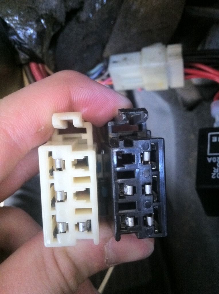
Turned out to be badly deformed female pins in the IGNITION SWITCH Harness connectors.
Disconnect the two ignition switch power connectors and carefully examine the female pins.. Ecpecially the ones that supply 12 VDC power to the switch.
See post 41 for pictures of damaged pins:
http://forums.corvetteforum.com/c5-t...and-p1153.html
Bill
Race Director


Joined: May 2012
Posts: 15,768
Likes: 3,283
From: Phoenix area, AZ
Helped another forum member reciently and he had ignition switch related issues. He cleaned the switch and had simular issues.
Turned out to be badly deformed female pins in the IGNITION SWITCH Harness connectors.
Disconnect the two ignition switch power connectors and carefully examine the female pins.. Ecpecially the ones that supply 12 VDC power to the switch.
See post 41 for pictures of damaged pins:
http://forums.corvetteforum.com/c5-t...and-p1153.html
Bill
Not to detract from the thread but I'm having many of the same codes the OP has popping up on a regular basis, although I'm not experiencing any system failures, and (knock on wood) everything works just as it should. Two of the codes I am getting are short to ground for both of the front turn signals, and these codes showed up after I cleaned my ignition switch according to your ignition switch thread instructions. Where might I check for the cause of these two particular codes? Is it the ground under the passenger side A-pillar?
Tech Contributor
Joined: Dec 1999
Posts: 32,910
Likes: 2,402
From: Anthony TX
CI 6,7,8,9,11 Vet
St. Jude Donor '08
Im going to post the DTC reference info from the service manual.
Does your DRLs function properly for both sides as a DRL and a blinker when you turn the blinker on??
There are TWO relays involved in the circuit, two light bulbs the multifunction switch and the BCM its self and a few ground connectors.
Has your BCM ot the passengers footwell ever been wet???
Bill
--------------------------------------------------------------------------------
DTC B2578 Right Front Turn Signal Monitor Circuit
Circuit Description
The BCM monitors the RF turn signal circuit in order to determine the status of the turn signal switch. If the BCM detects an oscillating voltage on the RH turn signal monitor circuit, the BCM interprets this as a RF turn signal ON request from the turn signal switch. The BCM will de-energize the RH DRL relay, which will disable the RF turn signal lamp (which is ON for the DRL), thus allowing the RF turn signal to flash. If the BCM does not detect an oscillating voltage on the RH turn signal monitor circuit, the BCM interprets this as the RF turn signal being OFF. The BCM will then energize the RH DRL relay and continue normal DRL operation. The BCM monitors the RH turn signal monitor circuit and determines how long voltage is applied. If the voltage is applied for longer than expected, a malfunction is present and a DTC will set.
Conditions for Setting the DTC
The BCM detects continuous battery voltage on the RH turn signal monitor circuit.
The condition must be present for longer than 5 seconds.
Action Taken When the DTC Sets
Stores a DTC B2578 in the BCM memory.
No driver warning message will be displayed for this DTC.
Conditions for Clearing the DTC
This DTC requires an ignition cycle in order to change from current to history.
The BCM no longer detects continuous battery voltage on the RH turn signal monitor circuit for longer than 5 seconds.
A history DTC will clear after 50 consecutive ignition cycles if the condition for the malfunction is no longer present.
Use the IPC clearing DTCs feature.
Use a scan tool.
Diagnostic Aids
The following conditions may cause an intermittent malfunction:
There is an intermittent short to voltage in the RH turn signal monitor circuit.
The turn signal switch or the hazard switch is internally shorted or is sticking.
The BCM needs to detect voltage oscillations on the RH turn signal monitor circuit in order to de-energize the RH DRL relay. If the BCM detects continuous voltage on the RH turn signal monitor circuit, the BCM interprets this as a short to voltage. The BCM will continue with normal DRL operation, and the RF turn signal will remain inoperative.
If the DTC is a history DTC, the problem may be intermittent. Perform the tests shown while moving related wiring and connectors. This can often cause the malfunction to occur. Refer to Intermittents and Poor Connections .
Test Description
The number(s) below refer to the step number(s) on the diagnostic table.
Tests if a DTC B2583 is stored in the BCM. If both the RH and LH turn signal monitor DTCs are stored, test the hazard switch and related circuits for a short to voltage.
Tests if the BCM is receiving oscillating voltage on the RH turn signal monitor circuit. If the test light is ON steady, the BCM will set a DTC B2578.
Tests if the BCM is receiving oscillating voltage on the RH turn signal monitor circuit. If the test light is ON steady, the BCM will set a DTC B2578.
Tests if the turn signal switch or related circuits are shorted to voltage.
Tests if the hazard switch or related circuits are shorted to voltage.
Tests if the instrument panel cluster turn signal indicator is shorted to voltage.
Tests if the body control module is shorted to voltage.
When the BCM is replaced, use a scan tool to perform the BCM RPO Reprogram procedure. Refer to Body Control Module (BCM) Programming/RPO Configuration .
Step
Action
Value(s)
Yes
No
1
Did you perform the BCM Diagnostic System Check?
--
Go to Step 2
Go to Diagnostic System Check - Body Control System
2
Install a scan tool.
Turn ON the ignition, with the engine OFF.
Select the BCM display DTC function on the scan tool.
Does the scan tool display DTC B2583?
--
Go to Step 10
Go to Step 3
3
Turn OFF the ignition.
Disconnect the RH DRL relay.
Turn ON the ignition, with the engine OFF.
Probe the RH turn signal monitor circuit at the RH DRL relay with a test lamp that is connected to a good ground. Refer to Power Distribution Schematics in Wiring Systems for electrical center circuit identification.
Turn ON the RH turn signals
Does the test lamp turn ON and OFF with the RH turn signals?
--
Go to Step 13
Go to Step 4
4
Does the test lamp remain illuminated?
--
Go to Step 5
Go to Turn Signal Lamps Inoperative
5
Disconnect the turn signal switch.
Does the test lamp remain illuminated?
--
Go to Step 6
Go to Step 9
6
Disconnect the hazard switch.
Does the test lamp remain illuminated?
--
Go to Step 7
Go to Step 10
7
Disconnect the instrument panel cluster.
Does the test lamp remain illuminated?
--
Go to Step 8
Go to Step 11
8
Disconnect the body control module.
Does the test lamp remain illuminated?
--
Go to Step 12
Go to Step 14
9
Repair a short to voltage in the turn signal switch circuit. Refer to Wiring Repairs in Wiring Systems.
Did you complete the repair?
--
Go to Step 15
--
10
Repair a short to voltage in the hazard switch circuit. Refer to Wiring Repairs in Wiring Systems.
Did you complete the repair?
--
Go to Step 15
--
11
Repair a short to voltage in the instrument panel turn signal indicator circuit. Refer to Wiring Repairs in Wiring Systems.
Did you complete the repair?
--
Go to Step 15
--
12
Repair a short to voltage in the turn signal monitor circuit. Refer to Wiring Repairs in Wiring Systems.
Did you complete the repair?
--
Go to Step 15
--
13
Replace the RH DRL relay. Did you complete the replacement?
--
Go to Step 15
--
14
Important
Perform the BCM RPO Reprogram procedure. Refer to Body Control Module (BCM) Programming/RPO Configuration .
Replace the BCM. Refer to Body Control Module Replacement .
Did you complete the replacement?
--
Go to Step 15
--
15
Use the scan tool in order to clear the DTCs .
Operate the vehicle within the Conditions for Setting the DTC as specified in the supporting text.
Does the DTC reset?
--
Go to Step 2
System OK
--------------------------------------------------------------------------------
Document ID# 581020
2000 Chevrolet/Geo Corvette
DTC B2583 Left Front Turn Signal Monitor Circuit
Circuit Description
The BCM monitors the LF turn signal circuit in order to determine the status of the turn signal switch. If the BCM detects an oscillating voltage on the LH turn signal monitor circuit, the BCM interprets this as a LF turn signal ON request from the turn signal switch. The BCM will de-energize the LH DRL relay, which will disable the LF turn signal lamp (which is ON for the DRL), thus allowing the LF turn signal to flash. If the BCM does not detect an oscillating voltage on the LH turn signal monitor circuit, the BCM interprets this as the LF turn signal being OFF. The BCM will then energize the LH DRL relay and continue normal DRL operation. The BCM monitors the LF turn signal monitor circuit and determines how long voltage is applied. If the voltage is applied for longer than expected, a malfunction is present and a DTC will set.
Conditions for Setting the DTC
The BCM detects continuous battery voltage on the LH turn signal monitor circuit.
The condition must be present for longer than 5 seconds.
Action Taken When the DTC Sets
Stores a DTC B2583 in the BCM memory.
No driver warning message will be displayed for this DTC.
Conditions for Clearing the DTC
This DTC requires an ignition cycle in order to change from current to history.
The BCM no longer detects continuous battery voltage on the LH turn signal monitor circuit for longer than 5 seconds.
A history DTC will clear after 50 consecutive ignition cycles if the condition for the malfunction is no longer present.
Use the IPC clearing DTCs feature.
Use a scan tool.
Diagnostic Aids
The following conditions may cause an intermittent malfunction:
There is an intermittent short to voltage in the LH turn signal monitor circuit.
The turn signal switch or the hazard switch is shorted internally or is sticking.
The BCM needs to detect voltage oscillations on the LH turn signal monitor circuit in order to de-energize the LH DRL relay. If the BCM detects continuous voltage on the LH turn signal monitor circuit, the BCM interprets this as a short to voltage. The BCM will continue with normal DRL operation, and the LF turn signal will remain inoperative.
If the DTC is a history DTC, the problem may be intermittent. Perform the tests shown while moving related wiring and connectors. This can often cause the malfunction to occur. Refer to Intermittents and Poor Connections .
Test Description
The number(s) below refer to the step number(s) on the diagnostic table.
Tests if a DTC B2578 is stored in the BCM. If both the LH and LH turn signal monitor DTCs are stored, test the hazard switch and related circuits for a short to voltage.
Tests if the BCM is receiving oscillating voltage on the LH turn signal monitor circuit. If the test light is ON steady, the BCM will set a DTC B2583.
Tests if the BCM is receiving oscillating voltage on the LH turn signal monitor circuit. If the test light is ON steady, the BCM will set a DTC B2583.
Tests if the turn signal switch or related circuits are shorted to voltage.
Tests if the hazard switch or related circuits are shorted to voltage.
Tests if the instrument panel cluster turn signal indicator is shorted to voltage.
Tests if the body control module is shorted to voltage.
When the BCM is replaced, use a scan tool to perform the BCM RPO Reprogram procedure. Refer to Body Control Module (BCM) Programming/RPO Configuration .
Step
Action
Value(s)
Yes
No
1
Did you perform the BCM Diagnostic System Check?
--
Go to Step 2
Go to Diagnostic System Check - Body Control System
2
Install a scan tool.
Turn ON the ignition, with the engine OFF.
Select the BCM display DTC function on the scan tool.
Does the scan tool display DTC B2583?
--
Go to Step 10
Go to Step 3
3
Turn OFF the ignition.
Disconnect the LH DRL relay.
Turn ON the ignition, with the engine OFF.
Probe the LH turn signal monitor circuit at the LH DRL relay with a test lamp that is connected to a good ground. Refer to Power Distribution Schematics in Wiring Systems for electrical center circuit identification.
Turn ON the LH turn signals
Does the test lamp turn ON and OFF with the LH turn signals?
--
Go to Step 13
Go to Step 4
4
Does the test lamp remain illuminated?
--
Go to Step 5
Go to Turn Signal Lamps Inoperative
5
Disconnect the turn signal switch.
Does the test lamp remain illuminated?
--
Go to Step 6
Go to Step 9
6
Disconnect the hazard switch.
Does the test lamp remain illuminated?
--
Go to Step 7
Go to Step 10
7
Disconnect the instrument panel cluster.
Does the test lamp remain illuminated?
--
Go to Step 8
Go to Step 11
8
Disconnect the body control module.
Does the test lamp remain illuminated?
--
Go to Step 12
Go to Step 14
9
Repair a short to voltage in the turn signal switch circuit. Refer to Wiring Repairs in Wiring Systems.
Did you complete the repair?
--
Go to Step 15
--
10
Repair a short to voltage in the hazard switch circuit. Refer to Wiring Repairs in Wiring Systems.
Did you complete the repair?
--
Go to Step 15
--
11
Repair a short to voltage in the instrument panel turn signal indicator circuit. Refer to Wiring Repairs in Wiring Systems.
Did you complete the repair?
--
Go to Step 15
--
12
Repair a short to voltage in the turn signal monitor circuit. Refer to Wiring Repairs in Wiring Systems.
Did you complete the repair?
--
Go to Step 15
--
13
Replace the LH DRL relay. Did you complete the replacement?
--
Go to Step 15
--
14
Important
Perform the BCM RPO Reprogram procedure. Refer to Body Control Module (BCM) Programming/RPO Configuration .
Replace the BCM. Refer to Body Control Module Replacement .
Did you complete the replacement?
--
Go to Step 15
--
15
Use the scan tool in order to clear the DTCs .
Operate the vehicle within the Conditions for Setting the DTC as specified in the supporting text.
Does the DTC reset?
--
Go to Step 2
System OK
--------------------------------------------------------------------------------
Document ID# 581021
2000 Chevrolet/Geo Corvette