When you click on links to various merchants on this site and make a purchase, this can result in this site earning a commission. Affiliate programs and affiliations include, but are not limited to, the eBay Partner Network.
My 99 recently decided it didnt want to roll down the windows or do the easy exit with the drivers seat. I ran through the dic codes and it says
ldcm-no comm.
rdcm-no comm.
scm- no comm.
ive read cleaning the grounds should be the first step in figuring how whats wrong. does anyone know the specific grounds that effect these modules? and whats the best way to clean out the connectors?
I KNOW that I always PREACH that many problems are caused by poor dirty grounds.
In you case, I believe that you have an issue with the CONNECTIONS in the SCM, LDCM, RDCM CONNECTORS
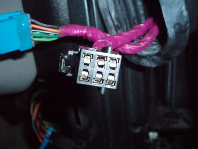
The SIX PIN POWER CONNECTORS are well known to FAIL. The FEMALE PINs inside the connectors spread apart and make **** poor electrical connections. This caused one or all of those modules to turn ON & OFF,,ON & OFF,,ON & OFF,,ON & OFF,,ON & OFF,, and that causes the module to CORRUPT the cars SERIAL DATA BUSS.
Pop out the door rubber accordion tubes and fish out the door connectors and pop open the six wire connector and look for SPREAD/DAMAGED Female pins..
The TOP ROW/Center Pin is a PRIME example of a damaged/ spread female pin:
The SEAT plug has the same pins in it and they can spread also.
BC
Last edited by Bill Curlee; May 25, 2016 at 02:38 PM.
I KNOW that I always PREACH that many problems are caused by poor dirty grounds.
BC
Would there be any advantage to eliminating the connector boxes and just soldering ring connectors to each wire and securing together to a ground post/screw at each location?
I am NOT a nuclear sub electrician... in fact I'm NOT an electrician, just a novice tinkerer (if that's a word) but, I think you have a GREAT idea... someone else may have done it, but if they have I haven't seen any post or threads about it... we'll see what the smart boys say
Sometimes something simple/obvious just keep getting overlooked...things that make you hmmmmmm
Last edited by 73Corvette; May 25, 2016 at 08:09 PM.
Reforming the connectors are a bandaid type fix. Unfortunately the connectors arent up to the job.
Pay special attention to the two connectors associated with the passenger side door jam.
As well there is a ground pack behind the battery (towards firewall) taped to the wire bundle. While you are at it, tape the wire looms especially where they sit on the sub frame behind the battery. I once lost a passenger side front o2 heater signal. The wire arced through to ground after chaffing off the paint on the sub frame.
Would there be any advantage to eliminating the connector boxes and just soldering ring connectors to each wire and securing together to a ground post/screw at each location?
Originally Posted by don37
Reforming the connectors are a bandaid type fix. Unfortunately the connectors arent up to the job...
Perhaps instead of eliminating the connectors by doing permanent links, replacing them would be a better solution.
Replacing the connectors with what would seem to be higher quality connectors may be also an alternative. Searching online I did find this, though I cannot verify the credentials of those who wrote it, so take it for what it is worth: (note the section I highlighted) Just food for thought. Would love to hear from the forum guru's on this subject.
C5 Chassis Ground Maintenance
This may solve a lot of electrical problems in a C5.
Many C5’s get the infamous "REDUCED ENGINE POWER", "TRACTION CONTROL FAILURE" and a host of random failure codes. After many, many hours of troubleshooting, replacing the BCM and TAC module, you may or may not have solved most of the drivability issues. But you still might be getting the random DTC failure codes. It may be time to determine whether you are having grounding issues. If you clean ALL of the chassis grounds the car will virtually stop throwing the "RANDOM" DTC failure codes. Just moving the wires in the chassis ground connector is enough to change the indications and make the issues stop happening. But it usually is not a permanent fix.
GM C5 Trouble Desk Engineers at Bowling Green, KY have pointed out that MANY of the C5 electrical issues can be directly linked to chassis ground problems. The engineers even go as far as to recommending that you chop off the factory under hood chassis ground connectors and combine all of the wires into a single ground lug. Most of us, however, will not want to LOP off the factory connector. Instead disassemble one of the ground plug connectors and you may be surprised how corroded the connectors really are.
It is recommended that any C5 owner that has had or who are having electrical issues, examine and clean the chassis ground connectors. This may save you from needlessly replacing expensive electronic modules. Each ground connector can be disassembled and cleaned in about 20 min.
Just cleaning the metal ground connection between the chassis and the plug is only a band aid solution. Simply removing the connector to clean the connection between chassis and the connector, may change the indications and make everything work properly. However, disassembly of the chassis ground plug and cleaning the contacts inside the connector is the correct method of solving the issue!
Here are some pictures of the under hood chassis ground connector and the corrosion that can be found. Taking it apart and cleaning it is a very straight forward procedure and if you follow this recommendation, you will be on the way to solving many of the electrical issues.
Here are some detailed pictures of the ground connector and the corrosion that was found inside it! I could not get the pictures to load but they are the same cleaning procedures as in other threads posted over the years.
UPDATE: Apologies to Bill Curlee as the above seems to be almost verbatim from a post by Bill, but the online source did not reference or credit him.
The Connectors pictured above are a MUCH better design, but, you need to pull up the connector SPECS and see how much current carrying capability that they are rated for. I know GM uses the pin type above for almost all low current SIGNAL circuits and the other type of pins (the failure designed ones) for low voltage higher current circuits.
LOPPING OFF OEM GM CONNECTORS.. Man,,, Its your car. If it were me, I would just purchase the SIX PIN Connector "PINS" and replace the bad ones. Its NOT difficult.
As for the OTHER connector in the door harness, Ive never seen it have an issue as it is the pin design as pictured above.
Ive worked on Submarine Electronics my entire Navy Career and the Military uses the Amphenol Deustch design PINS in almost ALL of their Amphenol Electrical Connectors.
We have draws and draws of the same style pins for thousands of different electrical connectors.
Good video on the MILSPEC connector and MILSPEC pins that the military uses.
The Connectors pictured above are a MUCH better design, but, you need to pull up the connector SPECS and see how much current carrying capability that they are rated for. I know GM uses the pin type above for almost all low current SIGNAL circuits and the other type of pins (the failure designed ones) for low voltage higher current circuits.
LOPPING OFF OEM GM CONNECTORS.. Man,,, Its your car. If it were me, I would just purchase the SIX PIN Connector "PINS" and replace the bad ones. Its NOT difficult.
As for the OTHER connector in the door harness, Ive never seen it have an issue as it is the pin design as pictured above.
Bill
Understood, just a question: Using the upgraded connectors you would still have to come out of one end of the connector with separate wires, then concatenate them into one ring terminal to be secured down by the ground screw to the frame, would you not? The OEM connector achieves that via the construction of the connector box and the cast tab on one end that is screwed down to the frame. Or am I missing something?
Understood, just a question: Using the upgraded connectors you would still have to come out of one end of the connector with separate wires, then concatenate them into one ring terminal to be secured down by the ground screw to the frame, would you not? The OEM connector achieves that via the construction of the connector box and the cast tab on one end that is screwed down to the frame. Or am I missing something?
Now I UNDERSTAND!! You were talking about the CHASSIS GROUND CONNECTOR and I was thinking you were considering replacing the SIX PIN DOOR HARNESS POWER CONNECTOR.
To ease your mind,, JUST HACK THAT GROUND CONNECTOR OFF and solder the wires into a single eyelet. That's the way the C6 chassis grounds are constructed..
That connector is just a PITA.
Bill
Bill
Thanks. Sorry for the confusion. I kept thinking if you have to then combine all those separate wires on one end of the upgraded connector anyway, why not do the same and eliminate the connector, and any potential failure of the pins or any resistance issues, and secure the ground wires (concatenated together to a single ring terminal) directly to the frame via the ground screw.
Now I UNDERSTAND!! You were talking about the CHASSIS GROUND CONNECTOR and I was thinking you were considering replacing the SIX PIN DOOR HARNESS POWER CONNECTOR...
The same thing happened to me, that's why I posted the upgraded connectors
Ive worked on Submarine Electronics my entire Navy Career and the Military uses the Amphenol Deustch design PINS in almost ALL of their Amphenol Electrical Connectors.
We have draws and draws of the same style pins for thousands of different electrical connectors.
Good video on the MILSPEC connector and MILSPEC pins that the military uses.


 Now I UNDERSTAND!!
