


N2MB WOT Box Wiring

Thread Starter
Racer


Joined: Sep 2015
Posts: 275
Likes: 17
From: peachtree city ga
I just went through this.
Use a 1/4" ratchet with 9/32 deep well socket. If you don't know which connector you want to take off, it is the one closest to the passenger quarter panel or B+ post on the side of the UHBEC.
Greg and I are putting together much better instructions. IF you cannot wait, PM me with email and I will send better pix than the instructions. It will be next weekend until I get this all put together.
Thread Starter
Racer
Joined: Sep 2015
Posts: 275
Likes: 17
From: peachtree city ga
Guys,
Sorry I have been busy with my own install. With the help of Greg and belatedly, N2MB, I am done with the physical install. Not the programming.
Here are the pix I have taken. I plan on putting together a job aid with corrective editing N2MB has on their website for the 2004. Should be the same for 99-04.
It will take me until next weekend I am guessing to finish.
Last edited by Richard A. Snitzer; May 19, 2017 at 01:36 PM.
Thread Starter
Racer
Joined: Sep 2015
Posts: 275
Likes: 17
From: peachtree city ga
This was a direct question to N2MB last night. When you cut A6 & E2, the "leads to the fusebox" are the short leads that are still attached to the fusebox. The "from" is the leads headed towards the ground/pavement.

Pro


Joined: Jan 2016
Posts: 680
Likes: 255
2021 C5 of the Year Finalist - Modified
These are great. I noticed you connected YELLOW wire to purple wire in pin 56. Are instructions wrong? it mentions C2-26..with red cover
Last edited by Efx; May 19, 2017 at 01:33 PM.
Thread Starter
Racer
Joined: Sep 2015
Posts: 275
Likes: 17
From: peachtree city ga
Pro

Joined: Dec 2015
Posts: 661
Likes: 182
From: Knoxville TN
[QUOTE=Efx;1594770699]Will update this thread with my progress. If anyone could confirm my wiring, that would be great... Also my box came with parameters set for srt4 dodge. Can anyone share their settings that work for c5z?
It may be a day or two till I have a chance but I can see if I can get a screenshot of mine and post it
It may be a day or two till I have a chance but I can see if I can get a screenshot of mine and post it
Pro
Joined: Jan 2016
Posts: 680
Likes: 255
2021 C5 of the Year Finalist - Modified
Ok so instructions on the website are partially wrong...
Are these correct?:
WOTBOX Blue wire -> Dark green wire Accelerator pedal sensor (at the pedal)
WOTBOX Green wire -> Grey wire Clutch switch sensor (at clutch pedal)
WOTBOX Black wire - ground
WOTBOX RED wire -> A6/E2 pink wires going in to Fusebox (cut)
WOTBOX ORANGE wire -> pink wires going to coil packs (cut)
WOTBOX YELLOW wire -> PCM pin 26 with GREEN inside cover
Thread Starter
Racer
Joined: Sep 2015
Posts: 275
Likes: 17
From: peachtree city ga
I highly recommend soldering even though it is a PITA.
Ok so instructions on the website are partially wrong...
Are these correct?:
WOTBOX Blue wire -> Dark green wire Accelerator pedal sensor (at the pedal)
WOTBOX Green wire -> Grey wire Clutch switch sensor (at clutch pedal)
WOTBOX Black wire - ground
WOTBOX RED wire -> A6/E2 pink wires going in to Fusebox (cut)
WOTBOX ORANGE wire -> pink wires going to coil packs (cut)
WOTBOX YELLOW wire -> PCM pin 26 with GREEN inside cover
Are these correct?:
WOTBOX Blue wire -> Dark green wire Accelerator pedal sensor (at the pedal)
WOTBOX Green wire -> Grey wire Clutch switch sensor (at clutch pedal)
WOTBOX Black wire - ground
WOTBOX RED wire -> A6/E2 pink wires going in to Fusebox (cut)
WOTBOX ORANGE wire -> pink wires going to coil packs (cut)
WOTBOX YELLOW wire -> PCM pin 26 with GREEN inside cover
Corvette Stories
The Best of Corvette for Corvette Enthusiasts

Top 10 Most Expensive Corvettes Ever Sold on Bring A Trailer
Brett Foote
10 Things Every Corvette Owner Needs (2026 Edition)
Michael S. Palmer
8 Most "Only Corvette Owners Understand" Quirks and Problems
Pouria Savadkouei
10 Reasons the C6 Z06 is Still A Performance Benchmark After 20 Years
Joe Kucinski
How Much Horsepower Every Corvette Engine "LOST" in 1972
Joe Kucinski
Top 10 DOs and DON'Ts for Protecting Your Convertible Top!
Michael S. Palmer
Top 10 Most Explosive Corvettes Ever Made: Power-to-Weight Ratio Ranked!
Joe Kucinski
150 hp to 1,250 hp: Every Corvette Generation Compared by the Specs That Matter
Joe Kucinski
8 Coolest Corvette Pace Cars (and Replicas) of All Time
Verdad Gallardo
Melting Slicks


Joined: Jun 2002
Posts: 2,246
Likes: 66
From: Middletown CT
Ok so instructions on the website are partially wrong...
Are these correct?:
WOTBOX Blue wire -> Dark green wire Accelerator pedal sensor (at the pedal)
WOTBOX Green wire -> Grey wire Clutch switch sensor (at clutch pedal)
WOTBOX Black wire - ground
WOTBOX RED wire -> A6/E2 pink wires going in to Fusebox (cut)
WOTBOX ORANGE wire -> pink wires going to coil packs (cut)
WOTBOX YELLOW wire -> PCM pin 26 with GREEN inside cover
Are these correct?:
WOTBOX Blue wire -> Dark green wire Accelerator pedal sensor (at the pedal)
WOTBOX Green wire -> Grey wire Clutch switch sensor (at clutch pedal)
WOTBOX Black wire - ground
WOTBOX RED wire -> A6/E2 pink wires going in to Fusebox (cut)
WOTBOX ORANGE wire -> pink wires going to coil packs (cut)
WOTBOX YELLOW wire -> PCM pin 26 with GREEN inside cover
That looks good to me.
Rich will be adding his notes and comments to this document when he gets time, but I'm going to post it now. Hopefully it will help clear things up.
Current revision is D
See post #35 for a wiring diagram I did. If anyone finds anything in either document that is incorrect, let me know and I will fix it.
Last edited by Greg_E; May 21, 2017 at 06:17 AM.
Melting Slicks
Joined: Jun 2002
Posts: 2,246
Likes: 66
From: Middletown CT
Efx: Can you delete the Revision A pdf in post #30. I've added some information to make it easier to find C1-A6 and C1-E2 on the Under Hood Electrical Center.
This is still a work in progress.
This is still a work in progress.
Last edited by Greg_E; May 20, 2017 at 07:33 AM.
Pro
Joined: Jan 2016
Posts: 680
Likes: 255
2021 C5 of the Year Finalist - Modified
Well Im in a pickle. I am not sure if I wired the yellow wire correct the first time or I am doing something wrong.
my c5z is 2003 and my PCM are red and blue.
Blue pcm pin 26 does not have purple wire
Red pcm pin 26 has purple wire where I connected the yellow one to.
Here the PCM with red connector with pin 26 purple wire
Here is 2nd PCM with blue connector, pin 26 is not purple wire

Here is overview of both PCMs unplugged
So confused

Melting Slicks
Joined: Jun 2002
Posts: 2,246
Likes: 66
From: Middletown CT
You did it correctly. C2 is the red connector. You do need to solder the purple wire that is dangling, to the purple and yellow wires if you haven't already done that.
I remember reading that they changed the connector color. Don't know what year that was.
I'll see if I can find it.
Even if the color of the connector changed, the wiring diagram didn't.
From the N2MB instructions:
"For 1999-2004 vehicles, the PCM connector with the red inner cover is the C2 connector"
That may only be partially true. It may have changed from red to green in 2004. We need to look into this.
Update:
Found it. 2004 Blue and Green Connectors. 2003 Blue and Red Connectors
1999-2003 C1 is Blue, C2 is Red. I think they made some changes to the 2004 PCM and changed the C2 connector to Green
http://corvetteforum.shelor.net/Corv...ts/Default.asp
Last edited by Greg_E; May 21, 2017 at 06:18 AM.
Pro
Joined: Jan 2016
Posts: 680
Likes: 255
2021 C5 of the Year Finalist - Modified
Yes I did solder the wires. Just took a pic prior to that for reference. Everything plugged in. Took 2 screenshots of the software for n2tmb to make sure everything wired up ok. Waiting for reply.
Will keep this thread updated with results.
Thanks again to everyone for their input. N2MB support has been outstanding btw.
Will keep this thread updated with results.
Thanks again to everyone for their input. N2MB support has been outstanding btw.
Melting Slicks
Joined: Jun 2002
Posts: 2,246
Likes: 66
From: Middletown CT
Can someone who has actually installed one of these check this wiring diagram and let me know if there are any errors or omissions.
My skills with MS Paint are about nil.
My skills with MS Paint are about nil.
Last edited by Greg_E; May 21, 2017 at 06:35 PM. Reason: Revision C. No changes. Just cleaned up the drawing.
Pro
Joined: Jan 2016
Posts: 680
Likes: 255
2021 C5 of the Year Finalist - Modified
With the help of this forum and Jon, i was able to wire and test the unit.
Everything works as it should. PM me if anyone needs more details about my install. I will post more pics of my wiring.
Part 2: i am cleaning out the mufflers from blown cats lol.
Drifting

Joined: Apr 2015
Posts: 1,893
Likes: 295
From: Buffalo NY
Your diagram is bang on.
With the help of this forum and Jon, i was able to wire and test the unit.
Everything works as it should. PM me if anyone needs more details about my install. I will post more pics of my wiring.
Part 2: i am cleaning out the mufflers from blown cats lol.
With the help of this forum and Jon, i was able to wire and test the unit.
Everything works as it should. PM me if anyone needs more details about my install. I will post more pics of my wiring.
Part 2: i am cleaning out the mufflers from blown cats lol.
What are your initial parameter settings?

Pro
Joined: Aug 2014
Posts: 604
Likes: 25
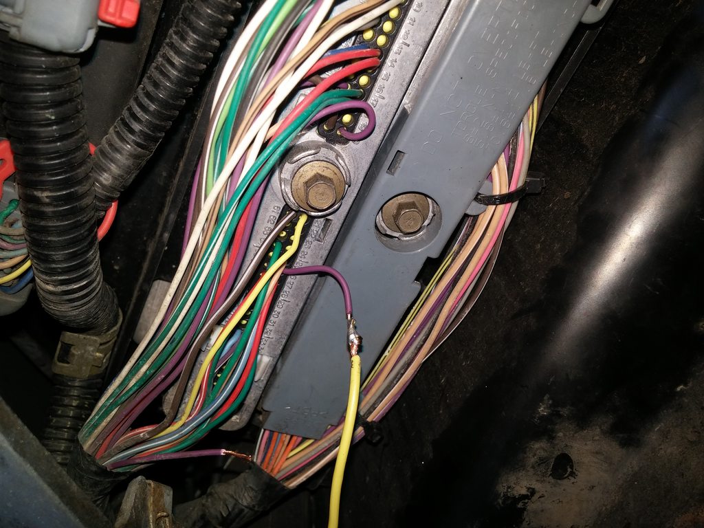
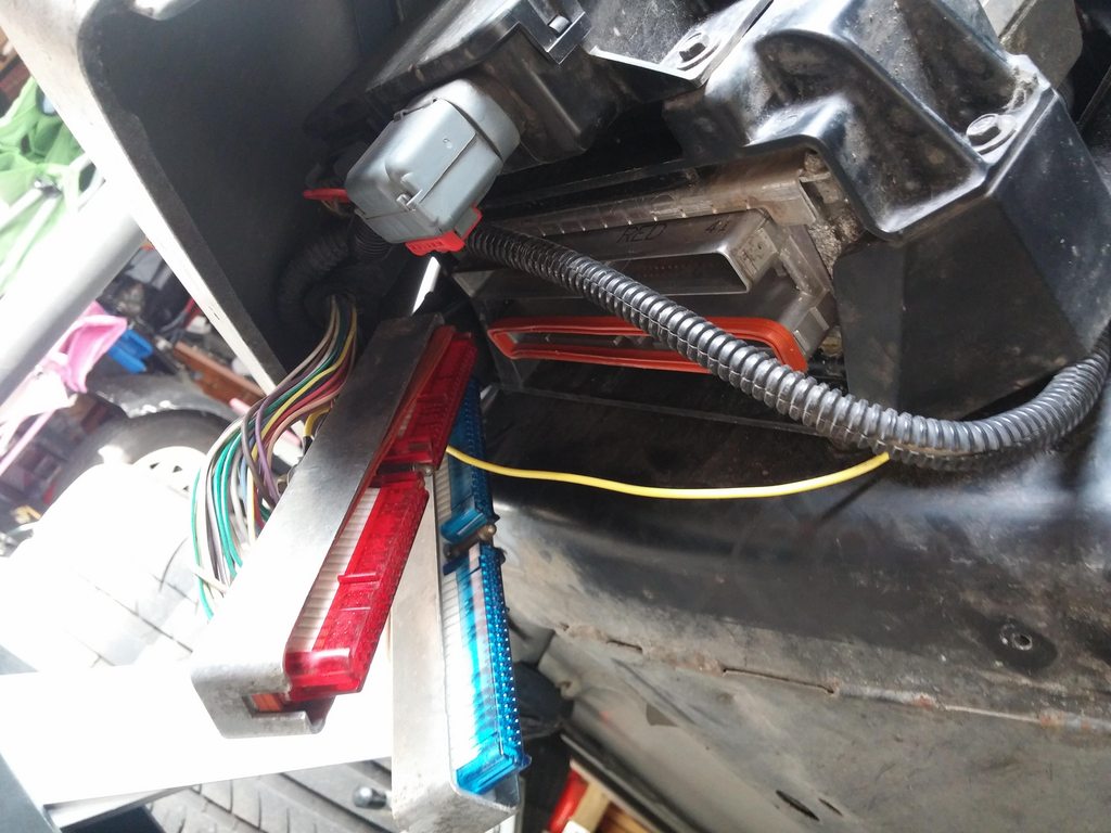
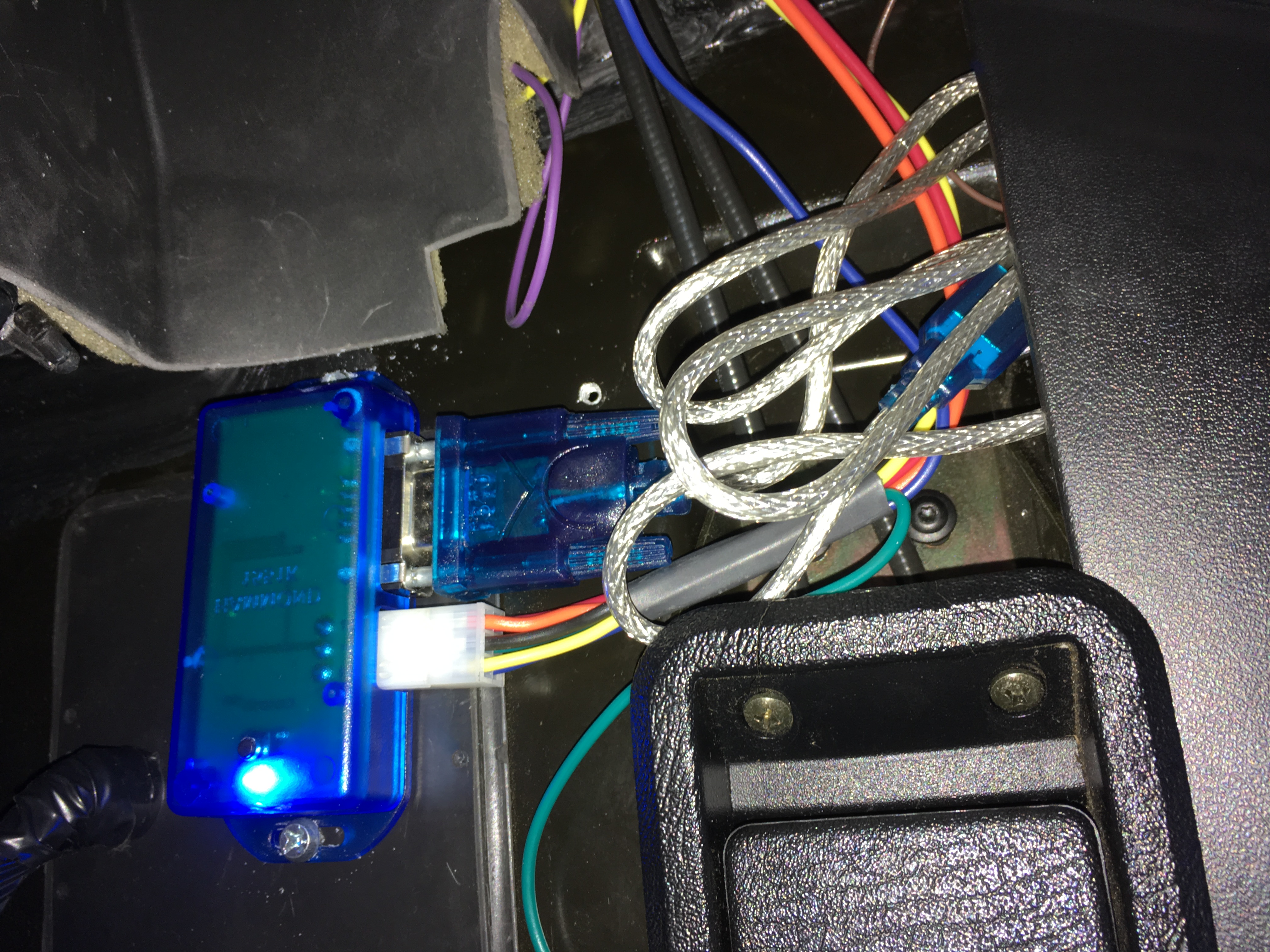
Need some help from you guys. I did my install this weekend: everything per instructions (and what I read here) except the trigger i tied into my brake light since im automatic.
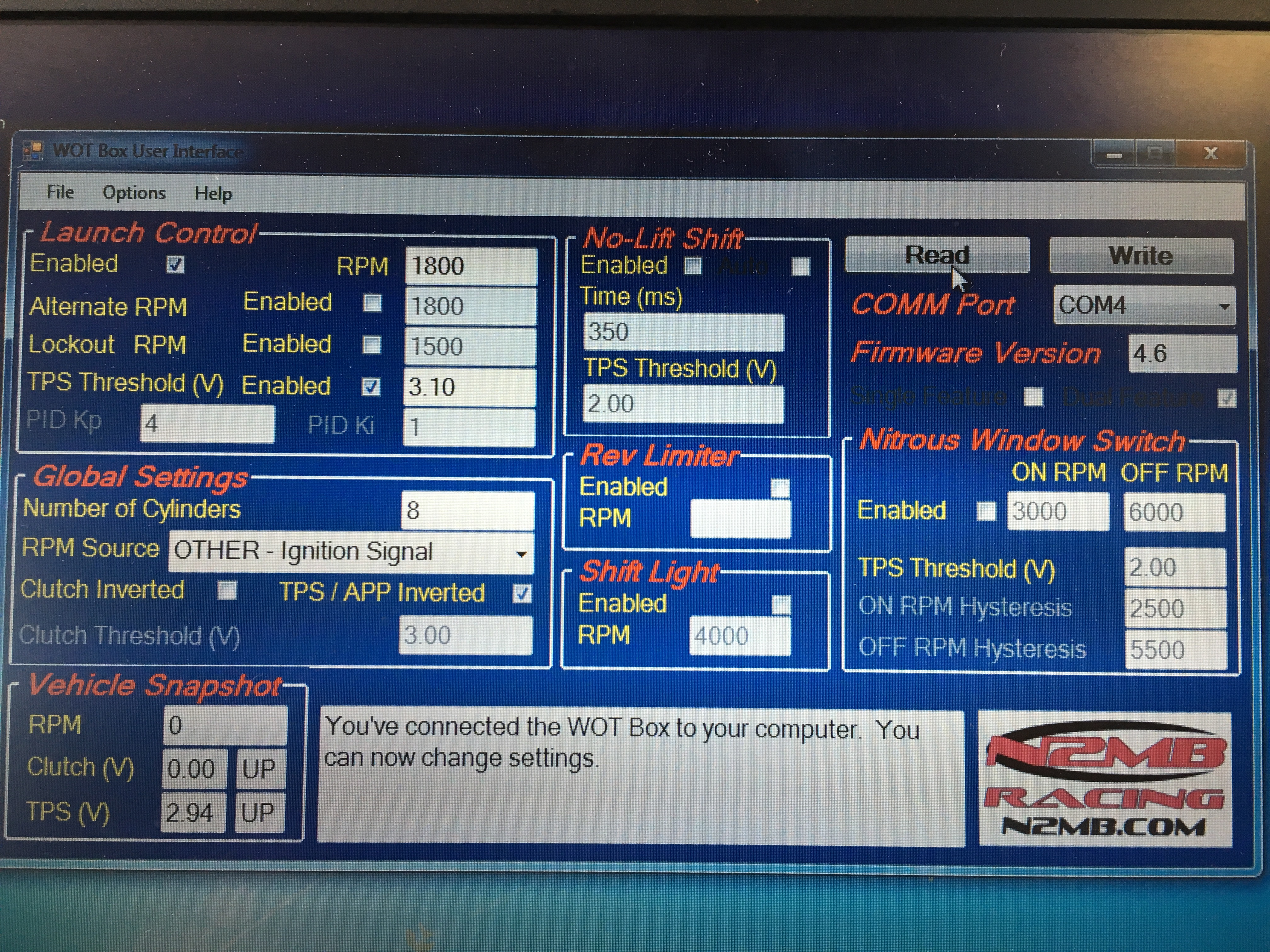
The testing is NOT working out.
I ran the setup, downloaded new firmware, etc. I then did the first
"READ" and saw that the TPS V was at 4.10, so I inverted the signal and both showed "UP" on the vehicle snapshot.
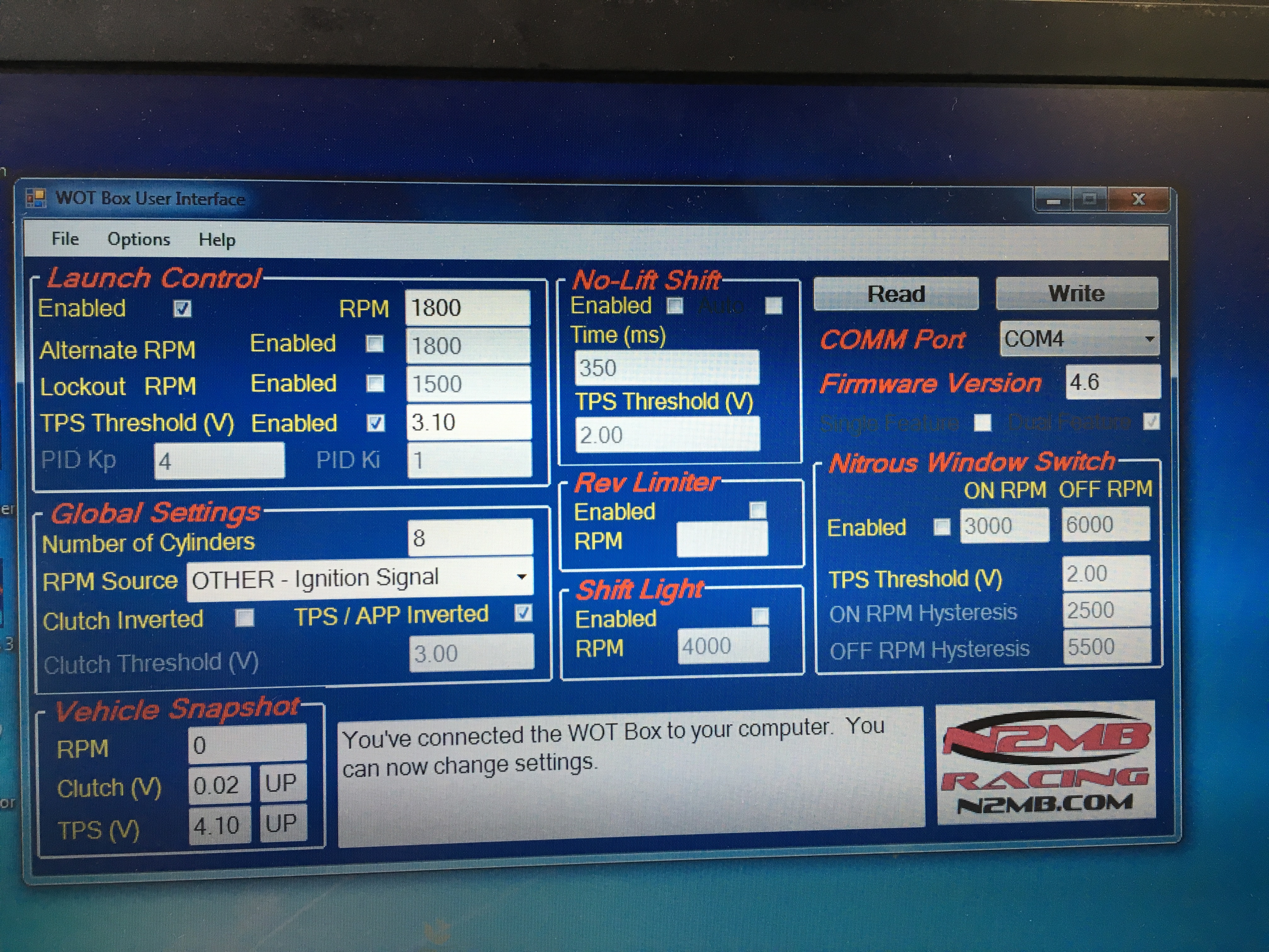
Then I mash the accelerator to the floor, the voltage changes, but it still shows "UP"
I even adjusted the TPS Threshold (V) and it still never seemed to work.
Anyone have any screen shots of their WOT Box User Interface with their setup?
Accelerator wire tap:
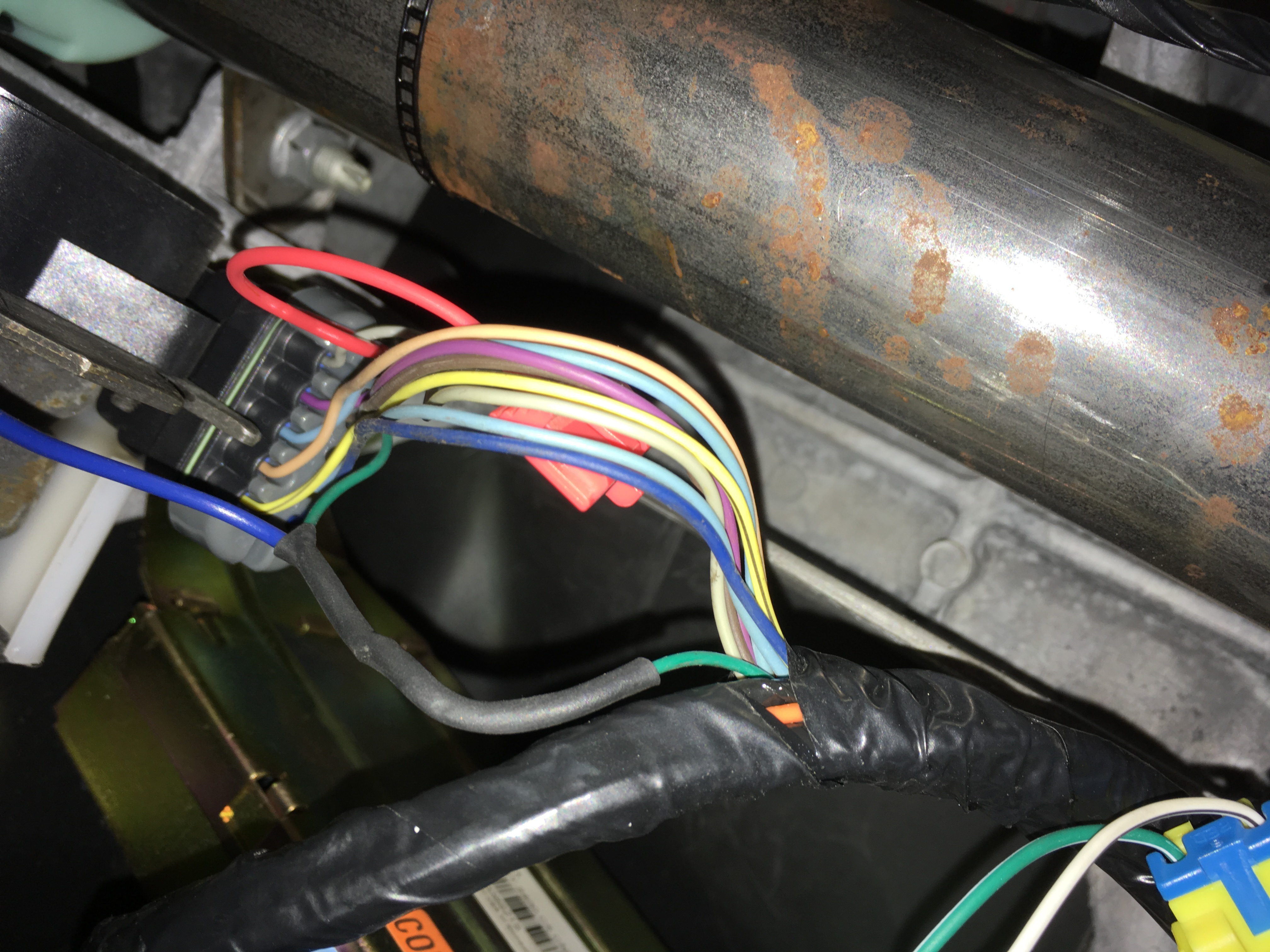
WOT Box install:
The testing is NOT working out.
I ran the setup, downloaded new firmware, etc. I then did the first
"READ" and saw that the TPS V was at 4.10, so I inverted the signal and both showed "UP" on the vehicle snapshot.
Then I mash the accelerator to the floor, the voltage changes, but it still shows "UP"
I even adjusted the TPS Threshold (V) and it still never seemed to work.
Anyone have any screen shots of their WOT Box User Interface with their setup?
Accelerator wire tap:
WOT Box install:
Melting Slicks
Joined: Jun 2002
Posts: 2,246
Likes: 66
From: Middletown CT
I'm not sure I can help you, but what wire did you splice into on the brake switch?
Pro
Joined: Aug 2014
Posts: 604
Likes: 25