


Floor Jack Adapter Beam
Thread Starter
Drifting


Joined: Apr 2006
Posts: 1,278
Likes: 2
From: Lexington TN. Retired Navy
I finally rec'd mine yesterday. Sorry no pics yet, but I'm sure you all have seen them / know what they are, they're even talked about on this forum. You know, it sets in the middle of the jack, both ends extend out to a pre determined length so you can lift the entire a$$ end or front end.
Anyway, what I didn't know is it only fits a certain jack model and mine ain't it.
So what did all of you do to get this to secure safely to the jack??? I may have to get a friend fabricate or replicate the center piece of the jack and either weld or bolt it the the adapter.
What say y'all?? Thanks for any suggestions.
Team Owner


Joined: Sep 2005
Posts: 20,352
Likes: 568
From: Ventura County, Calif

Safety Car


Joined: Aug 2006
Posts: 4,347
Likes: 25
From: Apache Junction AZ
I finally rec'd mine yesterday. Sorry no pics yet, but I'm sure you all have seen them / know what they are, they're even talked about on this forum. You know, it sets in the middle of the jack, both ends extend out to a pre determined length so you can lift the entire a$$ end or front end.
Anyway, what I didn't know is it only fits a certain jack model and mine ain't it.
So what did all of you do to get this to secure safely to the jack??? I may have to get a friend fabricate or replicate the center piece of the jack and either weld or bolt it the the adapter.
What say y'all?? Thanks for any suggestions.
Anyway, what I didn't know is it only fits a certain jack model and mine ain't it.
So what did all of you do to get this to secure safely to the jack??? I may have to get a friend fabricate or replicate the center piece of the jack and either weld or bolt it the the adapter.
What say y'all?? Thanks for any suggestions.
BJK
Last edited by 07MontRedcp; Dec 30, 2010 at 11:44 PM.
Melting Slicks


Joined: Jul 2010
Posts: 3,006
Likes: 245
From: Surprise, Az
I visited a local steel shop - Online metals located in Seattle, and ordered a pair of 4X2X3/16X26 in. rectangular tube. I cut some 1/4" rubber for pads, marked a centerline on the tube and centered it on the jack. I first tried it on the rear without problems, plenty long enough to fit a pair of 3ton rectangular based jack stands and slid the jack out when complete. I had to drive the front of the car onto some home-made ramps made from 2X8 wood to get it high enough to fit the jack under to the carriage/suspension assembly just behind the oil pan. With the 26" length, the jack stands posed no problem with floor jack removal. The tube is heavy, but rigid enough for the job.
Racer


Joined: Oct 2009
Posts: 288
Likes: 12
From: AZ
Anybody have pics of the finished unit? I have the same problem, had my jacking adapter shortened, now I need a way to secure it to my Harbor Freight Race Jack. I was hoping to be able to remove the adapter when I need to use my pucks to just lift a side�
Thx you

Thx you
Safety Car
Joined: Aug 2006
Posts: 4,347
Likes: 25
From: Apache Junction AZ
BJK
Racer
Joined: Nov 2007
Posts: 477
Likes: 0
From: Dallas Texas
I made my own using a 1.5 X 3 inch by 22 inch long piece of rectangular tubing. Then I welded in a length of tubing in the center that fits into the saddle of my Omega low profile jack. I am out of town so I cannot post pics right now, but can when I get home next week in anyone is interested.
Corvette Stories
The Best of Corvette for Corvette Enthusiasts

5 Best & 5 Worst Corvette Daily Drivers
Joe Kucinski
The Headlights of Every Corvette Generation Explained
Joe Kucinski
5 Best & 5 Most Overrated Corvette Track Packages of All Time!
Joe Kucinski
Every 2027 Corvette Engine Explained
Joe Kucinski
Designer Imagines A Corvette That Looks More Like a Corvette Than the Corvette
Verdad Gallardo
10 Ugly Corvettes That We Still Kinda Love
Joe Kucinski
Top 10 Most Expensive Corvettes Ever Sold on Bring A Trailer
Brett Foote
10 Things Every Corvette Owner Needs (2026 Edition)
Michael S. Palmer
8 Most "Only Corvette Owners Understand" Quirks and Problems
Pouria SavadkoueiLe Mans Master


Joined: Nov 2007
Posts: 6,422
Likes: 200
From: Wilkes-Barre Pa
I made up extensions using 1 1/2" square tubing. I welded 2 pieces together then welded a 4"x4" piece of 1/4" plate steel on each end and glued pieces of rubber on top of the plates. On the bottom in the center I welded on a strip of plate steel that would fit into the saddle of my jack. I made 2 of these extensions since the front and back jacking points require different lengths.
Last edited by MARSC6; Dec 31, 2010 at 09:45 AM.

CF Senior Member

Joined: Feb 2006
Posts: 23,313
Likes: 25
From: Tucson Arizona
I finally rec'd mine yesterday. Sorry no pics yet, but I'm sure you all have seen them / know what they are, they're even talked about on this forum. You know, it sets in the middle of the jack, both ends extend out to a pre determined length so you can lift the entire a$$ end or front end.
Anyway, what I didn't know is it only fits a certain jack model and mine ain't it.
So what did all of you do to get this to secure safely to the jack??? I may have to get a friend fabricate or replicate the center piece of the jack and either weld or bolt it the the adapter.
What say y'all?? Thanks for any suggestions.
Anyway, what I didn't know is it only fits a certain jack model and mine ain't it.
So what did all of you do to get this to secure safely to the jack??? I may have to get a friend fabricate or replicate the center piece of the jack and either weld or bolt it the the adapter.
What say y'all?? Thanks for any suggestions.
Thread Starter
Drifting
Joined: Apr 2006
Posts: 1,278
Likes: 2
From: Lexington TN. Retired Navy
Thanks Wayne O Iwill. One thing though, my adapter beam doesn't have a "pin", just a threaded hole and a bolt. But if could see a pic of yours
then I can get a better idea of what to do.
then I can get a better idea of what to do.
Team Owner
Joined: Sep 2005
Posts: 20,352
Likes: 568
From: Ventura County, Calif
In case you haven't seen this famous thread, there are some good pics that might help you:
http://forums.corvetteforum.com/c6-c...g-c6-pics.html
And here is a description of how to mod a Craftsman jack. Unfortunately the pics have been removed but you might get some ideas:
http://forums.corvetteforum.com/c6-c...ics-added.html
http://forums.corvetteforum.com/c6-c...g-c6-pics.html
And here is a description of how to mod a Craftsman jack. Unfortunately the pics have been removed but you might get some ideas:
http://forums.corvetteforum.com/c6-c...ics-added.html
Safety Car
Joined: Aug 2006
Posts: 4,347
Likes: 25
From: Apache Junction AZ
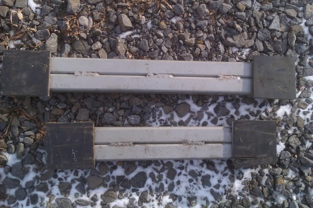
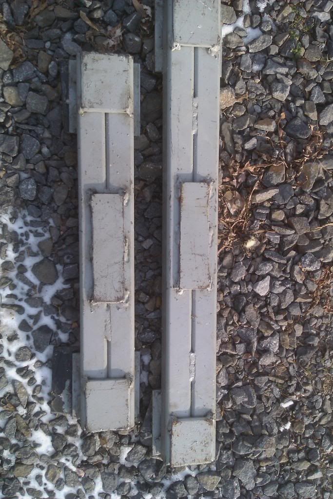
Okay, here are photo, as promised, of my cross beam adapter that I got sometime ago from Northern Tools. I took it to a machine local machine shop and the were able to remove the centering pin by grinding down the single weld that was on the the top reinforcement plate and then pressing the pin out. There was some bleed through of the weld, otherwise the pin would have just fallen out as the hole was a little over sized. They then put it on a lathe, turned it down to match the floor jack lift plate pin and welded it back in. I also had the body of the beam adapter shortened by 3" on each end and the adjustable arms shortened by 2 3/4". I did this because the front preferred lift points are only 22" (I think) apart and I just could not get the lift pads of the beam adapter close enough together to get them centered on the lift points. The reason a chose to shorten everything was so I could use the adjustability of the lift pads for both front and rear. I have the Race Ramp 12" blocks and I can now get the front of the car high enough to use those 12" pieces with the tires still on the car, really gives me a lot more room under the car.
EDIT: The fourth picture down is of the pin on the bottom of the floor jack lift pad.
BJK
EDIT: The fourth picture down is of the pin on the bottom of the floor jack lift pad.
BJK
Last edited by 07MontRedcp; Dec 31, 2010 at 12:43 PM.
Racer
Joined: Dec 2008
Posts: 404
Likes: 18
My cross beam adapter fits my jack and I am hoping to drive up on the 67 inch race ramps and them jack the back up with cross beam - hoping there is enough clearence to get jack and beam under rear when front is on the ramps ??
Bandit
Got my adapter 4400 lb capacity from a company called Dursban - jack company in NY - the center pin was longer than the ones from Summitt and high capacity of 4400 lbs.
$75 with shipping
Bandit
Got my adapter 4400 lb capacity from a company called Dursban - jack company in NY - the center pin was longer than the ones from Summitt and high capacity of 4400 lbs.
$75 with shipping
Le Mans Master
Joined: Aug 2005
Posts: 6,709
Likes: 1
From: Pacific Northwest
St. Jude Donor '06
I modified both of my floor jacks and crossbeams to work together. It didn't require any special tools, just a hacksaw, drill, file and tap. One crossbeam bolts onto the jack and the other has a pin that sits into a hole in the saddle.
I did get some 'C' channel welded to the bottom of the crossbeams so once I get the car up my jack stands fit into the channel and nothing can slip.
I did get some 'C' channel welded to the bottom of the crossbeams so once I get the car up my jack stands fit into the channel and nothing can slip.
Last edited by C-INRED; Jan 1, 2011 at 02:57 PM.
Racer
Joined: Dec 2008
Posts: 404
Likes: 18
I don't think you really have cut the center section dn or cut the extensions as in another thread the member merely put the rubber pads on the center section to lift the front end (used the same rubber pads that came with the cross beam). I guess since I have a few extra hockey pucks they should work as well with a little liquid nails glue the to the center section or just rest them on the adapter cross beam - SEE
http://forums.corvetteforum.com/c6-c...ml?forum_id=74
http://forums.corvetteforum.com/c6-c...ml?forum_id=74
Last edited by Bandit 2010; Dec 31, 2010 at 06:28 PM.


Drifting
Joined: Feb 2017
Posts: 1,778
Likes: 902
I would like to make my own also. I have some offcuts of thick lvl timber from a house extension.
Does anyone have measurements how wide these cross beams need to be for front and back and the distance centre to centre of the lifting ends?
Does anyone have measurements how wide these cross beams need to be for front and back and the distance centre to centre of the lifting ends?