When you click on links to various merchants on this site and make a purchase, this can result in this site earning a commission. Affiliate programs and affiliations include, but are not limited to, the eBay Partner Network.
Replaced Wheel Speed sensor and Still Getting C0045 code
Hi everyone,
On my 2005 Corvette I had
Service ABS, Service Traction Control, Service Active Handling Lights.
I plugged my code reader for abs and the code C0045 left rear wheel speed sensor circuit.
I first cleaned up the connection on the wheel speed sensors and reset it but the code still showed. So I guess it was the sensor.
I replace the whole wheel hub assembly and erased the code.
After driving it, I got the service and, traction control and active handling. I plugged my code reader again and it still shows C0045 code. I erased it a couple of times but still comes back.
Any thoughts?
Speed sensor is part of the wheel bearing hub, but would first check the ABS connectors since that is the other side of where the wires go from the speed sensor.
But yes, speed sensor's in the hub's do go out, even though the bearing are still fine.
Speed sensor is part of the wheel bearing hub, but would first check the ABS connectors since that is the other side of where the wires go from the speed sensor.
But yes, speed sensor's in the hub's do go out, even though the bearing are still fine.
what setting should I put the multimeter to check the ABS connector?
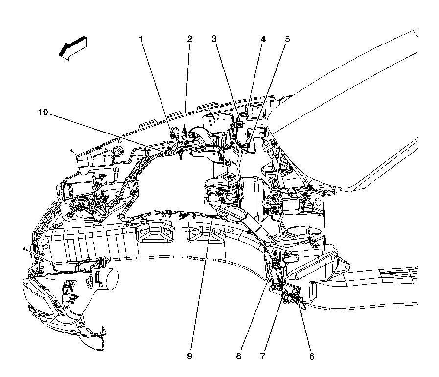
The wires from the LR Wheel speed sensor are the TN/OG wires, that end at the EBCM. Before the wires get from point A at the wheels speed sensor, to point C at the EBCM connector, then go through the C184 connector that is located on the passenger side fire wall that is about half way down the side of the battery. So on that note, pull the battery since at some point you will need to get to that connector.
#4 is C-184
So starting with the speed sensor if you can spin the wheel, Output should be 100MV AC across the sensor pins, and with the tire not spinning, should have 850-1350 ohms resitance if the sensor is good.
Next, pull the EBCM connector and light it up with spray electrical contact cleaner, as well as the pins on the EBCM to make sure they are clean as well. Now use a paper clip to jump pin A6 and A5 on the the disconnected EBCM connector (again, TN/OG wires). Now back at the connector for the wheel seed sensor, use the ohm meter in any resistance setting to look for continuity across the two connector pins since we have end of line EBCM connector pins connected to each other.
If you do not get a continuity reading across the wires, don't panic, since we still have to check the condition of the C184 connector. So at this point, go ahead and jump the two wires out at the speed sensor connector so both end of line wire runs are grounded to each other. Now disconnect the C184 connector from it self, and light it up with Electrical contact cleaner both sides. Now with the multi meter set to resistance, probe both sides of the connectors end pins on the TN/OG wires (a5/C4 pin without F55, A5/D4 pin is the car does have F55 on the C184 connector), and see if you have continuity through both connector ends (wires going back, and wires going forward since both ends are grounded out to each other on the TN/OG wires). If you do have continuity both sides to the grounded pin points, then use dielectric grease on all the connector pins with the jumpers pulled, and reconnect all the connectors. Hence since you already cleaned the sensor connector, suspect that the problem is either the C184 connector, or EBCM connector with corrosion problems.
If you don't show continuity on a set of wires when checking both sides of C184, then time to start chasing wires to find the problem.
With luck if its the wires leading back to the sensor that has the problems, it just the wire to connector crimp end piece that has the problem that can be solved right at the connector pins.
Note, if anyone is having problem with a front Speed sensors instead, Left front sensor goes through C159 connector, while right front goes through C160 connector as the middle connectors. Both back connectors go through the same C184 connector as middle point of wires.
If you not lucky and have a broken wire problem on the wires going back, then could be a broken wire where the wire loom drops down the back of the motor to run through the torque tube area next to the torque tube.
Hence the wire loom has a hard plastic piece where it sisters the torque tube, but before it gets to that hard center extra plastic piece shield, its only the flex nylon sleeved that flexes, and loves to snap wires right before the hard solid plastic shield piece in the torque tube (looms does a S kind of bend there).
To get to this areas to fix broken wires (really anywhere in the torque tube tunnel area), you have to pull the X pipe, then the torque tube cover, that will give you access up into the torque tube tunnel to get to the wires. Trust me, just went through this last year with a broken wire (and a few others about to snap as well at the S bend) in the torque tube area for the gas tank vent solenoid that the C188 white positive wire going back was cracked, and since I did not have a lift available to get the car high enough in the air to do the work myself, ended up dropping close to a grand to have the dealer repair a broken wire (and fix the others that where about to crack) instead.
Simply, what we are hoping for, is just corrosion problems at the connectors, than a can of electrical spray clean and some dielectric grease will resolve. Also to add, why in the hell GM put C184 and C188 (#3) right next to the battery, still baffles me. So on that note, when you are cleaning C184, pull C188 apart to clean it and dielectric grease it's pins as well.
Worst case, broken wire in the torque tube area that is a PITA to get to, or may have a cold solder joint on the ABS module controller, and which you need to pull the EBCM board to re-solder the cold solder joint instead.
Note, if you do have to pull the EBCM controller to correct a cold solder joint on the board header, take the time to clean up the solenoid channels and polish the valve stems as well. Before you put the board with cover back on the body of the ABS, light up the solenoids and valve with some silicon spray, and add a touch of RTV to the rubber seal so it seals off better to keep the water out of the controller board.
And so you keep a stiff upper lip through all this trouble shooting rabbit holes from hell, remember the mantra from the Hitchhiker's guide to the galaxy.
Note, help to chant "Don't Panic" right before you about to "Drop your basket" and start throwing tools.
Wow, Thank You so much DANO523 for this crash course time! It is really helpful. It is going to help out another person as well!
Before changing my wheel hub assembly, I cleaned the connectors with spray electrical cleaners and erased the code. But that wasn't it since the code came back.
After changing the hub and getting the code again, I was hoping for the EBCM connector not to be the problem.
I was trying to figure out where the EBCM connector from the left rear speed sensor goes to, so I can check it and spray it with the electric cleaner.
I will start tomorrow checking the wheel speed sensor first then the EBCM Connector and go from there.
When I lift the car do I need to put it in Neutral or will the tires spin freely in Parking (Automatic Transmission)?
I really like the last part you wrote: "Don't Panic" right before you about to "Drop your basket" and start throwing tools"
Done that before!
Last edited by powercorvette; May 8, 2020 at 08:34 PM.
The wires from the LR Wheel speed sensor are the TN/OG wires, that end at the EBCM. Before the wires get from point A at the wheels speed sensor, to point C at the EBCM connector, then go through the C184 connector that is located on the passenger side fire wall that is about half way down the side of the battery. So on that note, pull the battery since at some point you will need to get to that connector.
#4 is C-184
So starting with the speed sensor if you can spin the wheel, Output should be 100MV AC across the sensor pins, and with the tire not spinning, should have 850-1350 ohms resitance if the sensor is good.
Next, pull the EBCM connector and light it up with spray electrical contact cleaner, as well as the pins on the EBCM to make sure they are clean as well. Now use a paper clip to jump pin A8 and A5 on the the disconnected EBCM connector (again, TN/OG wires). Now back at the connector for the wheel seed sensor, use the ohm meter in any resistance setting to look for continuity across the two connector pins since we have end of line EBCM connector pins connected to each other.
If you do not get a continuity reading across the wires, don't panic, since we still have to check the condition of the C184 connector. So at this point, go ahead and jump the two wires out at the speed sensor connector so both end of line wire runs are grounded to each other. Now disconnect the C184 connector from it self, and light it up with Electrical contact cleaner both sides. Now with the multi meter set to resistance, probe both sides of the connectors end pins on the TN/OG wires (a5/C4 pin without F55, A5/D4 pin is the car does have F55 on the C184 connector), and see if you have continuity through both connector ends (wires going back, and wires going forward since both ends are grounded out to each other on the TN/OG wires). If you do have continuity both sides to the grounded pin points, then use dielectric grease on all the connector pins with the jumpers pulled, and reconnect all the connectors. Hence since you already cleaned the sensor connector, suspect that the problem is either the C184 connector, or EBCM connector with corrosion problems.
If you don't show continuity on a set of wires when checking both sides of C184, then time to start chasing wires to find the problem.
With luck if its the wires leading back to the sensor that has the problems, it just the wire to connector crimp end piece that has the problem that can be solved right at the connector pins.
Note, if anyone is having problem with a front Speed sensors instead, Left front sensor goes through C159 connector, while right front goes through C160 connector as the middle connectors. Both back connectors go through the same C184 connector as middle point of wires.
If you not lucky and have a broken wire problem on the wires going back, then could be a broken wire where the wire loom drops down the back of the motor to run through the torque tube area next to the torque tube.
Hence the wire loom has a hard plastic piece where it sisters the torque tube, but before it gets to that hard center extra plastic piece shield, its only the flex nylon sleeved that flexes, and loves to snap wires right before the hard solid plastic shield piece in the torque tube (looms does a S kind of bend there).
To get to this areas to fix broken wires (really anywhere in the torque tube tunnel area), you have to pull the X pipe, then the torque tube cover, that will give you access up into the torque tube tunnel to get to the wires. Trust me, just went through this last year with a broken wire (and a few others about to snap as well at the S bend) in the torque tube area for the gas tank vent solenoid that the C188 white positive wire going back was cracked, and since I did not have a lift available to get the car high enough in the air to do the work myself, ended up dropping close to a grand to have the dealer repair a broken wire (and fix the others that where about to crack) instead.
Simply, what we are hoping for, is just corrosion problems at the connectors, than a can of electrical spray clean and some dielectric grease will resolve. Also to add, why in the hell GM put C184 and C188 (#3) right next to the battery, still baffles me. So on that note, when you are cleaning C184, pull C188 apart to clean it and dielectric grease it's pins as well.
Worst case, broken wire in the torque tube area that is a PITA to get to, or may have a cold solder joint on the ABS module controller, and which you need to pull the EBCM board to re-solder the cold solder joint instead.
Note, if you do have to pull the EBCM controller to correct a cold solder joint on the board header, take the time to clean up the solenoid channels and polish the valve stems as well. Before you put the board with cover back on the body of the ABS, light up the solenoids and valve with some silicon spray, and add a touch of RTV to the rubber seal so it seals off better to keep the water out of the controller board.
And so you keep a stiff upper lip through all this trouble shooting rabbit holes from hell, remember the mantra from the Hitchhiker's guide to the galaxy.
Note, help to chant "Don't Panic" right before you about to "Drop your basket" and start throwing tools.
which one is the C184 connector from the front passenger side by the battery?
Checking in to what I have done so far!
I checked the Wheel Hub speed sensor for resistance and I did get about 1,xxx.
I also check the AC voltage and didn’t get much or none. Not sure if I had it in the right setting. I put it on ACV 750 and then ACV 290. Please see picture below.
I put the car in reverse to test the voltage since that’s what I saw on YouTube.
After that, I checked the EBMC connector that goes into the wheel speed sensor for resistance and I got 43.7. Below is a picture of the setting on my multimeter.
which one is the C184 connector from the front passenger side by the battery?
C184 is the smaller of the two, and the one upper right. The C188 is the larger of the two, and is the one lower left.
But since you are already there, disconnect all the 5 connectors in the area to light them up with spray contact cleaner to clean the pins, add in a little Dielectric grease on the pins (or just use WD 40 since it was designed to prevent corrosion on copper parts in the south pacific on airplane electronics), then reconnect the connectors.
Also, is your resistance check from the EBCM connector off the module, with the speed sensor connector pins grounded together? If yes, double check the resistance one more time after you get the C184 area connectors cleaned up, and see if the resistance decreases.
If resistances says same/same after the C184 connector clean up, and TPMS checks out and it connector/pins are cleaned as well, then best guess is problem is in EBCM board with a cold solder joint isntead.
Note, if you are running Braided brake line hoses, they can build up enough static electricity to cause problems with the wheel speed sensors not working correctly. So to solve that one, need to ground the braided house so they discharge to another/better ground, then to the wheel hubs isntead.
C184 is the smaller of the two, and the one upper right. The C188 is the larger of the two, and is the one lower left.
But since you are already there, disconnect all the 5 connectors in the area to light them up with spray contact cleaner to clean the pins, add in a little Dielectric grease on the pins (or just use WD 40 since it was designed to prevent corrosion on copper parts in the south pacific on airplane electronics), then reconnect the connectors.
I did it to all of them since I was already there.
for the ac voltage on the wheel speed sensor, is that correct settings because I didn’t get anything. Please see the pictures above on my other message.
I did it to all of them since I was already there.
for the ac voltage on the wheel speed sensor, is that correct settings because I didn’t get anything. Please see the pictures above on my other message.
Output on the sensor is 100 micro volts (hence .1 of a single AC volt) per pulse, so meter your using is not really going to pick up the pulses from the sensor when the wheel is being spun.
How the sensor works, and why it sends out the 100 micro amp pulses that the EBCM reads,
So you have continuity on the wires themselves, but double check that you don't have a fault to ground on the wires next.
Hence leave jumper in on the speed sensor connector pins so both wires are bonded to each other, then back at the EBCM connector off the unit, check each wire pin to ground on the frame, to make sure that each of the wires are not crimped/shielding worn off and the wire grounded to the frame. Hence if wires are shorted out to ground on the car , then Ac pulses from the sensor will not reach the EBCM.
So first check is to make sure that the wires are not cracked and you have continuity on the wires from end to end, and second test is to make sure that the wires are not grounded out to the cars ground to lose the low AC pulse from the sensor to the cars grounding next. From here, quick check on the speed sensor with a meter that can read the low AC voltage that the sensor should be pulse sending as the tire spins. From there if everything else checks out, leaves just the EBCM that is the problem child instead. And since it just the one sensor that the EBCM is having a problem with, screams cold solder joint problem on the board; with most likely the header pin solder joint since it been a problem for generations now as well.
C5 EBCM that had cold solder joint problems too, since the bath process does not work well when you have long/thick header pins that are sucking the heat in the bath process to create cold solder joints . Hence if you leave the board in the bath long enough to get a good solder joint on the thick pins, then you burn up the rest of the board smaller pin parts instead. Simply, on some boards that have huge/long metal header pins, they can be first bath produced to speed up the process on the thinner pin joints, but you have to go back in by hand to hand solder the larger header pin joints isntead. GM is about VE'g/product obsolescence of the cars, so this is extra soldering by hand is not done, and you end up with Cold solder joints that break free over time instead (do they can sell you replacement parts).
On the C6 EBCM, here are your header pin solder joints instead.
So long fat ones on the right of the while piece, total ***** of a solder joint to begin with, two semi thinner ones on the left, ***** as well, and same goes for the sensor input pins since although not as wide these 4 others, still long enough to suck up the bath heat to not produce a good solder joint to the board contact points.
Update!
After I cleaned and spray all connectors next to the battery front passenger side, I deleted the code and test drove it.
I drove it throughout the day and the only message that I got from my dash was service active handling system. NO MORE Service Traction control/ABS.
I plugged my code ready and no abs codes! I deleted it again went for a drive and the service active handling system came up again on the dash and no code showed up.
Any Ideas?
**Also I think there wasn't a good connection of the wheel speed sensor connectors like you mention Dano523.
I'm thinking if my old wheel speed sensor was good and just needed to clean the plugs!
Sounds like the wheel speed sensor problem was in the C184 connector, and now just need to get a Tech II on the car to pull the last of codes to figure out the service active handling system now.
If you can list the new code(s), should be able to make quick work out of resolving those problems as well. Could luck out with another connector problem that clean up will resolve (like the steering wheel postion sensor), or may have to dive into the EBCM if a problem in it (cold solder joint of sticking valve) instead.
I drove the Vette this weekend and decided to plug the code reader to see if
a code would pop up since the service active handling still shows on my dash.
the code that I got was C0710-52 (steering wheel angle sensor signal).
I clean that connection just to make sure and erased the code.
after driving it, I still get the service active handling and the code on the code reader.
Does this means that I have to replace the steering wheel angle sensor? (Is this common)
Also, Do I Loose power if I don’t fix it? Just trying to see if it reduces power. I may just ignore it if it’s not a big deal.
*The car had the clip already installed when I bought it.
Also, from another Thread, some one recommend to clean the a negative terminal under the battery box.
Which I sprayed it really well and went over it with a toothbrush.
Also, at this point, need to put a Tech II on the car so you can go into BCM data to look at the voltage/voltage change as you turn the wheel.
Wheel/tires straight, should read o volts, while turning the wheel to the left should cause a negative voltage reading, and then to the right a positive voltage reading change per degree the wheel is off center.
I bring this up, since sensor pop apart will cause problems, and if the steering rake was removed, wheel turned a turn, and rack put back on with wheel out one turn, reading on the sensor with the wheel/tires straight forward, will not read zero to cause problems as well.
Also, at this point, need to put a Tech II on the car so you can go into BCM data to look at the voltage/voltage change as you turn the wheel.
Wheel/tires straight, should read o volts, while turning the wheel to the left should cause a negative voltage reading, and then to the right a positive voltage reading change per degree the wheel is off center.
I bring this up, since sensor pop apart will cause problems, and if the steering rake was removed, wheel turned a turn, and rack put back on with wheel out one turn, reading on the sensor with the wheel/tires straight forward, will not read zero to cause problems as well.
Now that I read the thread from the link you provided, someone there asked if they had cams or harmonic dampener changed.
I did get my harmonic dampener changed. So could have the mechanic(no dealership) installed the position it incorrectly?
Is it something that I could do easily? (Position it correctly)
I don’t have a tech 2 or the mechanic that I go to.
Should I just go to the dealership and have them look at it?
I had those same massages and long story short it was steering position sensor was dislodge when the white keeper plastic ring fell off during cam change as the steering rack was moved around.
I too changed some hub bearings though I messed a wheel speed sensor during longer wheel studs installation.
powercorvette;
I did get my harmonic dampener changed. So could have the mechanic(no dealership) installed the position it incorrectly?
Being that the steering rack has to be pulled to install the HB, could be either the Sensor popped apart when the rack was pulled from the column and the column was allowed to telescope to far forward, or steering wheel could have been spun a turn , and the sensor no longer reading 0 volts when the wheel/tires are straight.
As for tech II, if you are going to wrench on the car at all yourself, then really need one to start with.
The VX GM Nano (MDI clone with step back capability to work at as a Tech II as well) is going to $109 right now on amazon, and work as a tech II using Tech2win on a laptop. Also, since its a MDI 1 clone, works with newer GM cars past 2012, that require the GDS2 software to be used as well.
So with tech II/Tech2win, can use it to make sure that the sensor is putting out the correct voltage with steering wheel changes (if the sensor popped apart or not with the steering column allow to telescope too far out) and even to check to make sure that the steering wheel was not spun a rotation and the sensor not Zeroing out with the wheels straight isntead.
If the steering wheel is clocked a turn, then steering column needs to be disconnect from the rack, the wheel turned the needed turn back, and rack coupling reconnected.
If the steering wheel sensor has popped apart and getting no voltage readings from the sensor (or wheel turned too many turns when disconnected from the rank to distroy the sensor instead) the entire steering column needs to be removed to correct/replace the sensor.
Bluntly, short of a wiring problem at the sensor or back up line, in either case, your pretty deep in to the car doing the repair. So on that note, would take the car back to the shop that installed the new HB, and let then double check there work. Before hand, since the grounding point for the system is under the battery tray, may not be a bad idea to pull the battery and give it a good cleaning in case the grounding the problem alone.
Here is a topic where the steering column was allow to telescope out to far when the steering rack was removed, the problem is caused with not only the sensor popping apart, but details on removing the rack to correct the sensor and re-seat the bearing as well. https://www.corvetteforum.com/forums...g-message.html
Update on the Service active handling.
Took it to the dealership to get it checked out. They found internal open in the steering wheel position sensor.
They also found my brake pedal switch bad, which I already knew.
The total to replace the steering wheel position sensor with pigtail and the brake pedal switch is $497.19.
Is that a fair price or could my local mechanic do this job.
Is it just replacing parts and no reprogramming from the dealership needed?
Update on the Service active handling.
Took it to the dealership to get it checked out. They found internal open in the steering wheel position sensor.
They also found my brake pedal switch bad, which I already knew.
The total to replace the steering wheel position sensor with pigtail and the brake pedal switch is $497.19.
Is that a fair price or could my local mechanic do this job.
Is it just replacing parts and no reprogramming from the dealership needed?
Don't want to buy a Tech II tool since I only work on the car for basic stuff.







 Replaced Wheel Speed sensor and Still Getting C0045 code