When you click on links to various merchants on this site and make a purchase, this can result in this site earning a commission. Affiliate programs and affiliations include, but are not limited to, the eBay Partner Network.
I saw this bump steer chart in an Engineering Publication by Duntov on the then-new '63 Corvette chassis.
This greatly concerned me. A 1/4" to 1/2" of toe in change on a bump?
I autocrossed at the Pro-Solo level for many years, in a Z28, and we went to great lengths to correct this.
It makes the car "dart" to one side when you hit a bump.
Many street cars these days are under .040" of bump steer.
Real race cars ty to get it down to .010"
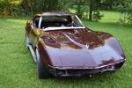
I know how to measure this, and I corrected this before, so now I am going to do it again, this time on my favorite car, a C3.
We have a lot of work to do!
I will be able to put an adjustment chart together once the parts are made. You will not even need a bump steer gauge.
Breaking News!
Parts are being designed!
Dan at Van Steel has agreed to work with me on developing these two parts to make this work.
He already makes some outstanding products and is more than willing to add to his selection, based on my testing results.
*****5 Stars for a great Corvette Vendor!*****
The currently available bump studs allow for fine adjustment of the tie rod end height. But it needs to be lengthened some more. He has the CAD program, and the skill in house to get that done. Just look at his recent high end aluminum front suspension offerings. His current bump studs are made to his specifications, in chrome moly, and he has the CAD design in house. He has agreed to design a new one a little longer for more adjustment range.
Plus he already has aluminum steering arms made for his recently added C7 bearing/aluminum hub conversion kits. He has the ability to make an arm for the stock hubs, which will replace the stock forged arm, with the increased drop we think is effective. Having some of the rod end drop handled by the steering arm, means less has to be handled by the bump stud. So the bump stud can be shorter and everything will flex less.
The tie rod joint is currently 1.25" below the arm. It needs to drop as far as 2" with some alignment settings. That is about 0.75" more than stock. Basically the two of us think splitting that drop 50/50 between a new arm, and the bump stud, makes the entire system less flex prone.
Here are my initial results. My front suspension had 2* caster, and zero toe at GM's normal ride height of D=2.25".
Unfortunately I got very large numbers. 0.400" toe-out (400 thou) at a 2" bump! Almost a half-inch!!!
(And you worry about 1/16" at the alignment shop. Haa!)
My goal is <.040". Or 10 times less. (Too ambitious?)
I got even larger numbers than Duntov. But I measured mine at a 23" spread, close to the tire tread.
If Duntov measured his at the rim edge of a 14" wheel, the difference makes perfect sense.
Other than that, my numbers jive with his.
I am almost glad it is a straight line, because that means it may be easier to fix. (Fingers crossed).
Hopefully, IIRC, lowering the outer tie-rod should correct some, all or most of this.
I need to add caster, which lowers the steering arm, which hopefully helps.
I also have a bump-steer adjusting kit, and can lower the tie-rod end some more.
More measurements to come, as I continue testing. And hopefully correcting this.
I’ve been looking at Van Steels Bump Steer kit and considering installing it on my 73.
Eric at Van Steel says it probably isn’t necessary on a street driven car, but I might go ahead and pull the plug and install it anyway.
I’ve been looking at Van Steels Bump Steer kit and considering installing it on my 73.
Eric at Van Steel says it probably isn’t necessary on a street driven car, but I might go ahead and pull the plug and install it anyway.
i couldn't find the bump steer kit on the Van Steel web site.
I know what it looks like, i have a set, can't remember if i bought it from Guldstrand or VBP, long long time ago, back when dinosaurs roamed the earth, when race cars shook the earth, etc. Sorry, I digress.
Yes all those companies sell a bump steer kit. There is also the old bump steer blocks from Guldstrand et al.
I will test as much as I can get my hands on.
Yes all those companies sell a bump steer kit. There is also the old bump steer blocks from Guldstrand et al.
I will test as much as I can get my hands on.
The VBP kit and I would guess Guldstrand, reduced my steering ratio. It positioned the pivot on the steering arm midway between the fast and slow positions. Also I had to drill out the taper to install it the original arm. I kept my originals and bought a used set just in case. Finally, on top of the adversity, the positive gain back in ratio was the installation of the Borgeson steering upgrade. Or so I'm told. I've never attempted to measure what I ended up with in terms of overall ratio. Maybe somebody else has and will chime in on their steering ratio number after their fix? Or how to accurately measure it?
The Van Steel kit looks like it adjusts the height of the tie rods with a specialized bolt, no big metal block. That suggests you can put it into either of the original holes on the steering arm? That would be the way to go providing the improvement is worth it. I did get a nearly perfect reduction (never bothered to graph this the way you probably want, but very little deflection just the same).
I have a set of tapered adapters that I think are the right taper to work. I also just happen to have the springs and shocks out for the next couple of weeks. Even if they're not the right taper they will probably work well enough to get some numbers. You've motivated me to give it a shot and see if I can add to your experiment.
Agreed. Imagine hitting a 1" bump with your right front wheel. That wheel toes-out 1/4" And steers the car right.
Then the wheel rebounds to 1" the other way, and the same wheel toes-in 1/4", and steers the car left.
And all this happens in one second.
What you feel is a twitch in the steering wheel.
I want to correct my car, but I also want to understand how all these parts work on our cars, and document it for the group.
My current test above was with MS pitman arm, MS centerlink, fast ratio holes, 2* caster.
Not all of the "fixes" I have heard about make sense to me. Physics wise.
Things I want to test:
MS slow ratio holes
increased caster, from 2* to 6*
Tubular upper a-arms
Bump steer kit
VBP "Ackerman" or bump steer blocks
Taller ball joints
shorter or longer tie-rods
Parts I have on the bench:
Parts I would like to try:
Last edited by leigh1322; Nov 21, 2025 at 10:31 PM.
i have ones similar to ignatz's blocks, and had good results when I measured the bumpsteer. I also installed longer upper ball joints, which increased the camber gain too. After making all the mods to the front suspension the car is very predictable now.
Jason, I remember your setup and our chats from earlier.
I just wish I could find a set of those bumpsteer blocks around somewhere!
Duntov makes some, but want big$ for them with steering arms.
How do the blocks impact steering speed, ackerman, and turn angle in reality? They should affect all of those, right?
They seem like an easy solution but I run some tight courses where these things matter.
The blocks do increase the Ackerman some according to geometry and theory, but I've never measured it myself. I didn't notice any significant reduction in turning radius, but I don't do a lot of tight autocrosses either to really judge it in those types of events. I have taken it to some road courses and didn't have any problems even in 90+ degree turns.
Originally Posted by leigh1322
Jason, I remember your setup and our chats from earlier.
I just wish I could find a set of those bumpsteer blocks around somewhere!
Duntov makes some, but want big$ for them with steering arms.
Yeah Duntov is the only place i've seen the bumpsteer blocks for sale, and they charge quite a bit for them now.








 Bumpsteer - Measuring it & Correcting it