When you click on links to various merchants on this site and make a purchase, this can result in this site earning a commission. Affiliate programs and affiliations include, but are not limited to, the eBay Partner Network.
Great story Ignatz.
Mine was similar, car changed yearly over many years.
I may have run similar Hoosiers for a while. 275/45-16.
Those and the Yoko 008Rs worked much better once I pushed the wheels out to 10" wide.
Back to front suspension.
Once you go deep into the details, it turns into quite the saga, as usual.
I realized my new SPC A Arms had 1/2" taller ball joints.
So that caused me to deep dive into ball joints.
I was thinking about ordering some stock height ones, and some longer ones. https://www.spcalignment.com/index.php/product/97160
SPC #97160. I ordered these because I could not get over 4* caster with any camber adjustment left, on my OEM control arms, even with my 1/4" slotted shafts. And I may want more caster or camber.
Easy camber and caster adjustment. Complete with 1/2" taller ball joints.
They offer a variety of ball joint heights:
#97001: OE (Original Equipment) length stud.
#97002: +0.25" over OE length stud.
#97003: +0.50" over OE length stud. (comes std)
Last edited by leigh1322; Nov 25, 2025 at 02:37 PM.
So with that out of the way I figured I would order some longer ball joint studs.
Jason Staley, and others, have successfully used longer B/J studs to increase the camber curve.
That seems like a very reasonable mod, and I wanted to document any bump steer changes.
SPC did not list a .75" or .9" Ball stud, one of which Jason used, so I called them.
Theirs stop at .5"
Well I could always get Howe right?
Wrong.
These are custom designed ball joints.
A tech finally measured one for me and they have a smaller than stock ball diameter.
Howe has nothing in that size.
Bummer!
I realized Jason used the older SPC arms, which use the bolt-in style of OEM ball joint.
SPC 94360 Arms also take 3 bolt ball joints
These use a std C3 Corvette ball joint that bolts in with 3 bolts.
OEM "correct" style sold by Corvette Vendors Corvette Central 572137
MOOG K6034 style
All of these have non replaceable ball studs.
But Howe make a version of the K6034 that is used for racing:
This is the Howe 22034S which is a direct replacement for a K6034, and it is rebuildable, and it has multiple stud lengths available.
It fits stock C3 A Arms as well as the other SPC arms.
It is available with multiple stud lengths up to 0.9", as a ball joint, or as replaceable studs.
Howe 223049 is the .9" taller version, 223045 is the .5" taller version.
Here are the replaceable studs:
So the sleek looking SPC 97160 arms take a custom designed ball joint, that has a 30mm / 1.181" diameter on the ball stud.
All the others take the K6034 style ball joints have a much larger 36.5mm / 1.437" diameter ball stud.
You can only get those custom ball joints from SPC, in only 3 heights, and they have a whopping 33% smaller friction area.
Not sure if I am going to keep them or not.
Need to regroup.
SPC makes these for multiple chassis, and the tech told me the curved arms and the taller ball joint are required on some applications. Trucks, B Bodies, etc.
But he had no info on Corvettes.
Last edited by leigh1322; Nov 25, 2025 at 03:22 PM.
Something else that increased Caster does.
Yes it helps the car to go straighter by increasing the trail or the self-centering effect.
But it also increase neg Camber as you turn the wheel.
These are measured numbers.
Increasing the Caster will also increase the Camber as you turn the wheel.
You can gain a degree or more of negative camber as you turn the wheel for a roughly 45 mph turn, as Ignatz is doing above.
Static Camber + Camber Gain + Caster Gain - Body Roll = Dynamic Camber
It can let you run less static camber, which is better for braking.
There are many ways to wind up with zero to -.5 Camber at speed.
Duntov Racing Corvettes runs 7* Caster in their 800HP BB C3 Vintage race cars.
And as light as 350# springs.
But a perfect camber curve & bump steer curve.
I do not believe in making the car too stiff, BTDT.
Stiff was great on dry concrete, very go cart like. Very quick response.
But it was horrible in the wet, or in the bumps. Virtually uncontrollable.
Let that suspension work!
My 5-7* Caster goal is the main reason I will NOT consider a manual steering corvette.
Duntov Racing said they used to subscribe to the manual steering theory, but with 2* caster the driver got very tired arms in a race, and then they added power steering, with 7* caster, and the car is so much faster. And so much less tiring to drive!
And much easier to "catch" when the rear end slides badly. OOPS!
Like that will ever happen.
Last edited by leigh1322; Nov 25, 2025 at 06:11 PM.
We have our first measured bump steer results:
The steering arm drops ~1/8" (.118") for every degree of caster you add.
This is with the lower control arm held perfectly still
The Bump Steer blocks were 1" thick to improve the bump steer, and the GM '80 Power book says lower the tie-rod 3/4" to improve the bumpsteer.
But none of them mention how much Caster. I am assuming 1-2*, since both of them were likely dealing with manual steering.
Now with modern power steering, and 5-6-7* caster, we need a different bump steer correction.
The old "thumb rules" no longer apply.
Last edited by leigh1322; Nov 25, 2025 at 06:13 PM.
The above chart, when interpreted with Arkus Duntovs Guidance, and the Guldstrand Bump Steer blocks, gives me a target.
Dunto said drop it 3/4". Guldstrand said drop it 1"
If both are talking about a MS car, with 2* caster, then our zero bump steer target should be around 1.0" to 1.25" down on the steering arm, from the 0 caster position.
That is not that much further down than what the 6* or 7* positions give me.
Maybe another .45"
Time to test.
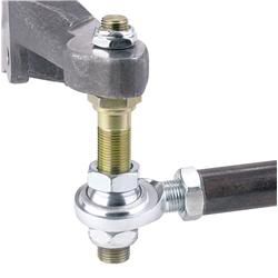
Here is the complete C3 Bump Steer kit as sold by many corvette vendors. For $500-600.
It is an absolute waste of $ to put the fancy adjuster on the centerlink end. That will do absolutely nothing.
I spoke with Dan at Van Steel and he sold me just the parts shown below, for the steering arm end only.
Much less at $161
Much Improved today. No time for numbers, just a quick ugly video.
Specs: 7* caster, MS slow ratio steering arm hole, .625" spacers on Van Steel Bump Steer kit. But it only lowers the tie rod .49" from before, the rod end is different too.
Bump Steer total is maybe .060-.080" over 5 inch of travel. Or somewhere around .016" per inch.
Let's call this a success!
The very first measurement had .825" of movement over 5 inches, for .160" per inch.
More measuring and more graphs after the holiday.
I do like the way the dial indicator barely moves now, vs the first time when it spun like a tornado!
It graphed even better than I thought.
Only .006" toe change at 1" bump and .010" at 2"
That is race car territory!
I will do the other caster values later. And make a graph and/or a table for you.
I do not expect the 5* Caster values to be very much higher, maybe a little, it may still be under .040" bump.
Most of the toe change is now on front end rebound, about .020" per inch. But who cares the front end is up in the air anyway!
Ok a drag racer would care.
Thanks for doing all this, it really made my decision on purchasing the parts from Van Steel.
I guess I better place my order before they get the notion to raise their price.
I'm not entirely convinced that the blocks reduce the steering ratio relative to the power steering hole in the arm, at least not near center.
On their own they appear to place the tie rod between the two original holes, but that would only reduce the ratio if the blocks were installed perpendicular to the tie rod.
Looking at ignatz's picture from above, they're actually installed at an angle relative to the tie rod. The tie rod, new hole location, and power steering hole location are all right in line with each other, which means the ratio would be the same (while driving straight).
That would change as the front wheels turn more. The inner wheel would begin to steer faster than the power steering hole while the outer would steer slower because that's what Ackerman does. So maybe they slow things down a tad at higher steering angles (since the outer tire will determine the turn radius), but not all the time.
That looks very much like mine.
Van Steel maybe?
If you have some where from 5-7* of caster, that should take almost all of your bumpsteer out.
What I am attempting to do is to make a chart, that guys can use, without having to actually use a bumpsteer gauge.
Sounds great Leigh, I believe I got mine before Van Steel had them, possibly Speed Direct but cant be certain. Not at home at present so can’t check if I have the invoice but was before 2013.
Sounds great Leigh, I believe I got mine before Van Steel had them, possibly Speed Direct but cant be certain. Not at home at present so can’t check if I have the invoice but was before 2013.
Post #577 of your build thread
Originally Posted by CraigH
Car handles great but given its fairly low it does still exhibit some bump steer.
Am thinking of adding this modification to the steering to dial it out.
They may have been what I purchased but they look a bit different to the ones on my 71. When I get home I will check, but the Van Steel ones look similar to mine and any will do the job.
I have just the hiem joint steering rod end of the Van Steel kit.
And VBP tubular adjustable tie rods.
The new rod ends are a little shorter than before, so I just ordered some new 1" longer tubular rods from Speedway, as well as some bump steer studs with longer shafts.
I have more experimenting and documentation to do.
This stuff is so easy to do on a bare frame, with no body, springs or shocks in the way.
It would be so much more difficult later! LOL
Basically I want to come up with a couple of charts, so if, or when, I change the alignment, I can re-correct the bump steer by doing "X". I did something similar back when I was racing.
I might as well document andpublish the charts along the way, so that others could just follow the "recipe" and enjoy corrected bump-steer, and could do so on an assembled car, without the need for all the measuring or disassembly.
That's the plan anyway, let's see if it works out.
I am glad a couple of you are following along!
BTW: I have had some great conversations with Dan at Van Steel in the past. We have discussed me helping him prototype a part or two for them. I should talk to him about this as well.
Been away for a few days, but this is an interesting thread. As to turning radius, I found this old video I took from the inside of the car showing the steering input. At that point, the car setup had snap oversteer if I applied brakes during a corner, so I had to break hard and then throttle thru the corner to keep it settled.