


Big 3 pics
Burning Brakes


Joined: Feb 2006
Posts: 1,085
Likes: 3
From: Ottawa Ontario, Canada
Subscribing!
I need to ask a question... Bill clearly states that those who are placing extra load demands on their car's electrical system will benefit from these modifications.
My car is electrically stock, save for a smaller Odyssey battery (PC680). I just cleaned the contacts in my ignition switch (thanks for the writeup Bill!) as preventative maintenance, but was hoping to see higher voltages displayed on the gauge. At startup it held nicely at 14.1-14.4V, then gradually dropped and held at 13.9V.
Then I loaded the system as much as I could; blower motor on high, rear defroster ON, radio cranked, full lights with high AND low beams (pull and hold stalk), brake lights on, emergency flashers flashing. Voltage dropped to 13.2V and held steady, and increasing engine RPM did not affect output (no I don't have UD pulleys).
Then I switched everything OFF, and voltage climbed to 13.5V and held steady even when reving the engine.
So to summarize, on startup the system is capable and willing to produce in excess of 14V, but once running for a while and/or loaded down voltage drops to the mid/low 13's and seems content staying there. I don't feel that those voltages do much for charging the battery... I have a battery charger that has a 2.0 amp setting, and when charging at 2 amps the voltage reports back at only ~13.3 volts (this is with a battery in an "operational" state of charge, not depleted).
Will "Big Three" mods improve this situation to where steady state operation will increase to high 13's/low 14's?
Burning Brakes
Joined: Feb 2006
Posts: 1,085
Likes: 3
From: Ottawa Ontario, Canada
Just did a little more investigation with a multimeter. Voltages are at alternator/battery/DIC:
Startup, No Extra Load: 14.6/14.4/14.2
Full Load (RR Def, AC, Lights, etc.): 14.6/14.1/13.6
Fully Warmed Up, No Extra Load: 13.9/13.7/13.5
So it would seem my alternator and electrical system are working pretty normally after all since there's about a 1.0V drop between the alternator's output and the DIC voltage under high load, and about half of that drop between the alternator and the battery.
I would assume, then, that the Big Three could eliminate most of the 0.5V drop between the alternator and the battery, but the 0.5V drop between the battery and DIC are there to stay unless I upgrade the wiring to the +Bus power inside the car. I guess following Bill's advice to beef up the battery terminal's crimped connections with a good heaping helping of solder couldn't hurt, either.
Seeing this definitely shows how a high current aftermarket stereo could wreak havoc on the car's voltage if the only power cable installation was from the battery to the amp(s)... the 0.5V drop I'm seeing with my car would be doubled every time the current draw doubled (and this is on a presumably "healthy" charging system). I'm not sure how much current I was drawing during my little "test", but I'd bet even a moderately powerful amplifier could easily double or triple the overall power demand which would mean an extra 1.0-1.5V drop (in theory of course). Seeing things in this light, it's easy to imagine a powerful system dropping the overall voltage into the single digits - and maybe even threatening the fusible links!

Tech Contributor


Joined: Dec 1999
Posts: 32,910
Likes: 2,402
From: Anthony TX
CI 6,7,8,9,11 Vet
St. Jude Donor '08
Something else to consider... Even if you install WELDING CABLES up to the ignition switch,,, The IGNITION SWITCH flows the current that it supplies the internal car circuits thru a very small contact inside the ignition switch:

And then it only uses a very small portion of that switch contact to complete the circuit.
SOOOOOOOOOO,,,,,, unless you make the contact patch on the ignition switch BIGGER,, it cant flow any more current. Unless you have a recently cleaned switch, any carbon on the contact surfaces will limit the voltage that you see on that IPC meter/DIC volt meter. Measure the voltage on the CIGAR LIGHTER when you are driving and see how that compares to the IPC voltage/DIC voltage.
CAN YOU MAKE THE CONTACTS SURFACES INSIDE THE IGNITION SWITCH BIGGER??????
YES!! To a point, yes you can. If you open the ignition switch and put some wet and dry sand paper between the closed contacts on one of the contact switches inside the ignition switch and sand the two contacts so that when there closed they make better contact, the switch contacts can pass more current before it starts to heats up and when the switch closes under load, it will arc less. Your not increasing the contact patch much but,,, it doesn't take much more contact area to make it work better.
Re-arching the tension arm on the switch to provide more contact pressure on the switch contacts and sanding the contacts to get more surface area & polishing the contacts will make your switch work better.
The battery voltage and the amount of current and voltage that the battery needs,,, controls the output of the alternator. If the battery doesn't need 14.5 VDC to keep the battery charged, it wont output that much. When you crank the engine, thats a very big CURRENT demand on the battery. The voltage out of the alternator needs to increase to recharge the battery. As the battery recharges,, the alternator will output less. As long as your charging above 12.5 VDC,, your still charging the battery. 13.5 is perfectly normal.
If you have mega watt power drains added to your electrical system like a very high wattage amp, your alternator may not be able to keep up with the demand o the battery. That would necessitate a bigger alternator.
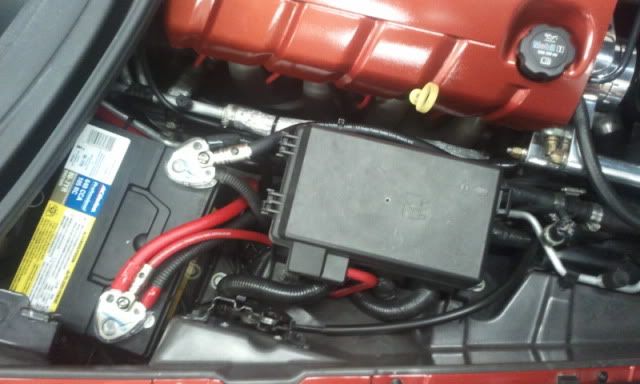
If you add a high current device to your cars electrical circuit (EXAMPLE: Heated seats ) Make sure that the actual load is taken off the HOT at ALL TIMES Buss. I added my heater seat high current load to the B+ terminal at the under hood electrical center. The low current control circuit is powered from the AUX Power HOT in RUN and Start circuit that comes from the ignition switch:
Here is the ADDED high current heated seat supply wire on the B+ circuit:

BC
Bill
And then it only uses a very small portion of that switch contact to complete the circuit.
SOOOOOOOOOO,,,,,, unless you make the contact patch on the ignition switch BIGGER,, it cant flow any more current. Unless you have a recently cleaned switch, any carbon on the contact surfaces will limit the voltage that you see on that IPC meter/DIC volt meter. Measure the voltage on the CIGAR LIGHTER when you are driving and see how that compares to the IPC voltage/DIC voltage.
CAN YOU MAKE THE CONTACTS SURFACES INSIDE THE IGNITION SWITCH BIGGER??????
YES!! To a point, yes you can. If you open the ignition switch and put some wet and dry sand paper between the closed contacts on one of the contact switches inside the ignition switch and sand the two contacts so that when there closed they make better contact, the switch contacts can pass more current before it starts to heats up and when the switch closes under load, it will arc less. Your not increasing the contact patch much but,,, it doesn't take much more contact area to make it work better.
Re-arching the tension arm on the switch to provide more contact pressure on the switch contacts and sanding the contacts to get more surface area & polishing the contacts will make your switch work better.
The battery voltage and the amount of current and voltage that the battery needs,,, controls the output of the alternator. If the battery doesn't need 14.5 VDC to keep the battery charged, it wont output that much. When you crank the engine, thats a very big CURRENT demand on the battery. The voltage out of the alternator needs to increase to recharge the battery. As the battery recharges,, the alternator will output less. As long as your charging above 12.5 VDC,, your still charging the battery. 13.5 is perfectly normal.
If you have mega watt power drains added to your electrical system like a very high wattage amp, your alternator may not be able to keep up with the demand o the battery. That would necessitate a bigger alternator.
If you add a high current device to your cars electrical circuit (EXAMPLE: Heated seats ) Make sure that the actual load is taken off the HOT at ALL TIMES Buss. I added my heater seat high current load to the B+ terminal at the under hood electrical center. The low current control circuit is powered from the AUX Power HOT in RUN and Start circuit that comes from the ignition switch:
Here is the ADDED high current heated seat supply wire on the B+ circuit:
BC
Bill
Last edited by Bill Curlee; Oct 13, 2011 at 01:28 AM.
Corvette Stories
The Best of Corvette for Corvette Enthusiasts

Top 10 Most Expensive Corvettes Ever Sold on Bring A Trailer
Brett Foote
10 Things Every Corvette Owner Needs (2026 Edition)
Michael S. Palmer
8 Most "Only Corvette Owners Understand" Quirks and Problems
Pouria Savadkouei
10 Reasons the C6 Z06 is Still A Performance Benchmark After 20 Years
Joe Kucinski
How Much Horsepower Every Corvette Engine "LOST" in 1972
Joe Kucinski
Top 10 DOs and DON'Ts for Protecting Your Convertible Top!
Michael S. Palmer
Top 10 Most Explosive Corvettes Ever Made: Power-to-Weight Ratio Ranked!
Joe Kucinski
150 hp to 1,250 hp: Every Corvette Generation Compared by the Specs That Matter
Joe Kucinski
8 Coolest Corvette Pace Cars (and Replicas) of All Time
Verdad GallardoBurning Brakes
Joined: Feb 2006
Posts: 1,085
Likes: 3
From: Ottawa Ontario, Canada
Originally Posted by Bill Curlee
Something else to consider... Even if you install WELDING CABLES up to the ignition switch,,, The IGNITION SWITCH flows the current that it supplies the internal car circuits thru a very small contact inside the ignition switch:
I think there's some merit in the Big Three, even for a stock electrical system. Since I plan to add an upgraded stereo in the spring, these mods should be a no brainer anyway.
Originally Posted by Bill Curlee
If you add a high current device to your cars electrical circuit (EXAMPLE: Heated seats ) Make sure that the actual load is taken off the HOT at ALL TIMES Buss. I added my heater seat high current load to the B+ terminal at the under hood electrical center. The low current control circuit is powered from the AUX Power HOT in RUN and Start circuit that comes from the ignition switch:
Tech Contributor


Joined: May 2003
Posts: 7,035
Likes: 134
From: North Augusta, SC

Tech Contributor
Joined: Dec 1999
Posts: 32,910
Likes: 2,402
From: Anthony TX
CI 6,7,8,9,11 Vet
St. Jude Donor '08
The only problem with using the screw by the fuse box is the fact that the wire connecting it to the battery is only 6 gauge (at least that's what it is on a non-Z C6). If someone runs a 0g power wire from the fuse terminal to a monster setup, the 6g wire may become your fuse

The battery hot wire from the battery terminal to the starter is not fused and if that baby shorts out, it will go critical in short order.
BC