
Lets Blow Up an Ammeter !
 06-22-2011, 06:14 PM
#41
Melting Slicks


But that is also what proves the ammeter circuit is in parallel with the red 10 awg wire. If current is flowing through the 10 awg wire, it is also flowing through the ammeter circuit but to a smaller degree given the higher resistance in the 16 awg wires. That's why the ammeter must be calibrated to read the entire charging circuit flow, rather than just the flow through the ammeter itself.
When I changed my alternator to the CS144, I upgraded the charging circuit by adding another wire in parallel with the red 10 awg charging circuit. That caused my ammeter to read about 1/2 of what it did before and that's because I changed the resistance of the charging circuit and caused less current to flow through the ammeter circuit. If current wasn't flowing through the ammeter circuit, my readings would not have changed.
Circuits in parallel will each carry a portion of the current based on the resistance of each circuit. Current flows through the ammeter circuit. It has no choice unless the circuit is open.
Try this experiment: Temporarily jumper another 10 gauge wire from the horn relay to the other end of the red 10 awg wire. After doing so, monitor your ammeter and compare it to the circuit without the temporary jumper.
DC
 06-22-2011, 06:58 PM
#42
Race Director

Actually I have traced out where the ammeter circuit connects to the main circuit. Your description of how it connects is exactly right.
But that is also what proves the ammeter circuit is in parallel with the red 10 awg wire. If current is flowing through the 10 awg wire, it is also flowing through the ammeter circuit but to a smaller degree given the higher resistance in the 16 awg wires. That's why the ammeter must be calibrated to read the entire charging circuit flow, rather than just the flow through the ammeter itself.
When I changed my alternator to the CS144, I upgraded the charging circuit by adding another wire in parallel with the red 10 awg charging circuit. That caused my ammeter to read about 1/2 of what it did before and that's because I changed the resistance of the charging circuit and caused less current to flow through the ammeter circuit. If current wasn't flowing through the ammeter circuit, my readings would not have changed.
Circuits in parallel will each carry a portion of the current based on the resistance of each circuit. Current flows through the ammeter circuit. It has no choice unless the circuit is open.
Try this experiment: Temporarily jumper another 10 gauge wire from the horn relay to the other end of the red 10 awg wire. After doing so, monitor your ammeter and compare it to the circuit without the temporary jumper.
DC
Interesting the comments about the disputed winding wire size.
Changing the resistance length in the #10 wire should allow for heavier winding wire in the gauge.
I commented in post #7 for a real reading, even a clampon digital with an ammeter tested to failure would dispell doubts as to the design intent.
 Interesting discussion.
06-22-2011, 08:05 PM
Interesting discussion.
06-22-2011, 08:05 PM
#44
Team Owner

If the ammeter leads are terminated by a single piece of wiring, then only the current produced by the shunt resistance voltage (millivolts) and the resistance of the ammeter coil can be generated in the ammeter circuit, itself. Current takes the path of least resistance. Hundredths of an ohm is a lot less than a few hundred ohms of coil wire in the ammeter. THERE CAN BE NO SIGNIFICANT CURRENT FLOWING THROUGH THE AMMETER LEADS AND THE AMMETER.
06-22-2011, 09:15 PM
#45
Melting Slicks
If the ammeter leads are terminated by a single piece of wiring, then only the current produced by the shunt resistance voltage (millivolts) and the resistance of the ammeter coil can be generated in the ammeter circuit, itself. Current takes the path of least resistance. Hundredths of an ohm is a lot less than a few hundred ohms of coil wire in the ammeter. THERE CAN BE NO SIGNIFICANT CURRENT FLOWING THROUGH THE AMMETER LEADS AND THE AMMETER.
Your theory about the current carrying capacity of the ammeter was disproved by Roger's experiment. You will not likely believe the results of that experiment until you duplicate it for yourself.
Someone needs to put a real ammeter in series with the ammeter circuit and watch the current flow under various charging circuit conditions.
DC
Last edited by DC3; 06-25-2011 at 05:03 PM.
06-22-2011, 10:44 PM
#46
Le Mans Master

Member Since: Aug 2006
Location: mount holly NC
Posts: 7,002
Received 1,254 Likes
on
972 Posts
C3 of Year Finalist (appearance mods) 2019

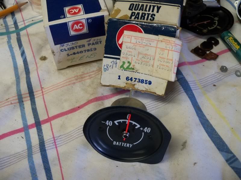
Are these real ammeters?
Someone said they are "Galvanometers" and the needle going - or + indicates if electricity is flowing to or from the battery.
Any truth to that?
Someone said they are "Galvanometers" and the needle going - or + indicates if electricity is flowing to or from the battery.
Any truth to that?
06-22-2011, 11:17 PM
#47
Team Owner
What is a "real ammeter"? In my early years, I worked in the Metrology Laboratory of a GM division where we calibrated everything from simple pressure gauges to 100,000 pound load cells. Shunt ammeters were the predominant method of measuring current. So, yes, these things are 'real ammeters'.
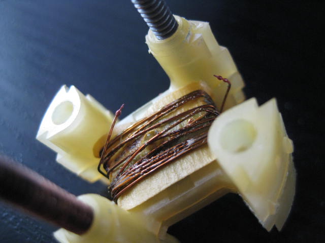
The resistance of the lead wires in the ammeter circuit are irrelevant. The resistance in the ammeter loop is that of the ammeter coil wire. I have been in my ammeter (as I described in an earlier post) and it has lots and lots of very fine wire in it. Why am I not running current through it to prove it can't take it? Well, because it will fry...and I really like my ammeter the way it is, of course. Why not 'burn' yours?
I'm still waiting to hear from anyone else that has an ammeter similar to that posted by Roger (with the BIG green wire in it). Not sayin' it didn't come from the factory, but I'd like to hear from another poster that theirs looks the same inside. Heck, any of the vendors that sell these things should know what size wire is in them....and if the design changed from fine wire to heavy wire.
 06-23-2011, 03:39 PM
#50
Team Owner
Blowing up the gauge was my plan,but now I'm rethinking whether or not that is possible. I'm beginning to think this thing is like a bulb,you can't run anymore through it than it is willing to accept. 
Just like putting a 12v test light between the neg battery terminal and the neg cable,you can turn on whatever you want and the test light bulb will not blow,even trying to engage the starter won't blow the test light.
Just like putting a 12v test light between the neg battery terminal and the neg cable,you can turn on whatever you want and the test light bulb will not blow,even trying to engage the starter won't blow the test light.
So, here goes. If we go back to V=IR, and assume we have 12 volts of driving force. Let's also assume for a minute that the wire, and the ammeter have zero resistance. Rearranging V=IR into I=V/R, when you hooked up the bulb in series with the ammeter, that circuit will draw a number of amps equal to 12 divided by the resistance in the bulb, since given our assumptions, that is the only resistance in the circuit. When you added the fan in series, it seems to me (and this is where I am totally talking out of my hind end), that you would have increased the resistance in the circuit with the same voltage, such that the amperage would actually go DOWN. I would expect this to result in the bulb being dimmer than when you ran it alone, but it doesn't appear to be, or at least not much. When you ran the two bulbs and fan together, I couldn't tell from the picture, did you run them in series, or parallel? Running two in series would increase the resistance of the circuit relative to one bulb, but running two in parallel would decrease the resistance relative to one bulb, so that becomes important. I think that as long as you keep putting stuff in series, you will keep increasing the resistance, so you could line up dozens of items and you wouldn't blow the ammeter, but sooner or later, some of the stuff wouldn't work so well any more.
06-23-2011, 04:55 PM
#52
Race Director
Thread Starter
Depending on the year, the shunt point connections are different, but the principal is the same.
Interesting the comments about the disputed winding wire size.
Changing the resistance length in the #10 wire should allow for heavier winding wire in the gauge.
I commented in post #7 for a real reading, even a clampon digital with an ammeter tested to failure would dispell doubts as to the design intent.
No fusible links and no ammeter to check draw.
06-23-2011, 09:51 PM
#53
Melting Slicks
I'm still waiting to hear from anyone else that has an ammeter similar to that posted by Roger (with the BIG green wire in it). Not sayin' it didn't come from the factory, but I'd like to hear from another poster that theirs looks the same inside. Heck, any of the vendors that sell these things should know what size wire is in them....and if the design changed from fine wire to heavy wire.
DC
06-23-2011, 10:16 PM
#55
Melting Slicks
I'll see your

 and raise you a .
DC
06-24-2011, 08:53 AM
#56
Team Owner
Anyway, what looks weird to me is that even with the one bulb on, the ammeter is pinned at -40 amps. So, either the bulb has an incredibly low impedence, or there is something else going on here.
06-24-2011, 09:03 AM
#57
Race Director
Thread Starter
Someone mentioned if 1 1/2 volts pegs the needle then 12 volts will cook it but it doesn't.
I'm merely a student now.
 06-24-2011, 09:11 AM
#58
Team Owner
Someone mentioned if 1 1/2 volts pegs the needle then 12 volts will cook it but it doesn't.
I'm merely a student now.
I'm merely a student now.
Last edited by Derrick Reynolds; 06-24-2011 at 09:13 AM.
06-24-2011, 09:30 AM
#59
Race Director
Thread Starter
How did you do the test to find that 1 1/2 volts pegs the needle? Hooking it up to a 1.5 volt battery with no other load on the circuit? How did you do the 12 volt test? Based on what I have seen here, the ammeter does have very low resistance. If that is true, putting the ammeter in a direct circuit for the battery will essentially be creating a short circuit, and your amperage in the circuit will come very close to the amperage capacity of the battery you are using. I'm not sure I would want to do that with a car battery, did you?
When speaking of 12v I was referring to what you see in my pics,every time I attached the bulb or fan it pegged the meter.
The 1 1/2 volts was just a AA battery connected to both ammeter terminals.
Your right if I tested the same with a 12 volt battery that would be a short to ground , should cook the meter. Apples to Oranges.
06-24-2011, 09:58 AM
#60
Pro

Member Since: May 2011
Location: Karlsruhe (Germany)
Posts: 708
Likes: 0
Received 32 Likes
on
17 Posts

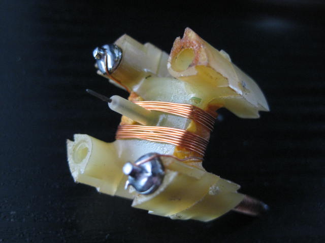
here is a pic of my blown Ammeter when i had bought my Vette.
I think this wire could keep 6-8Amps before it starts to melt.
(Think usally max ~ 4Amps run over it)
Knowing the resistance of the coil you can calculate the allowed direct load to it in a 12V circuit.
But in the car it is used in parallel to another wire, as mentoned above.
So 90% of the current is going trough the fat wire near the engine.
This would mean 4Amp trough the gauge, 36Amp trough the fat wire.
You can fix it by your own when its blown