


1971 Journey

Thread Starter
Melting Slicks


Joined: Apr 2010
Posts: 2,795
Likes: 1,196
From: Canberra Australia
2025 C3 of the Year Finalist - Modified
I don�t have a diagram but this is how it works.....
Stock
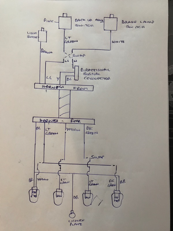
The outer rear light has 2 filaments. One for parking lights (that stays the same) and one that is both brake and turn signal. It is fed from a merge of the directional signal connector and the white stop light wire.
The inner rear light is fed from a single light green wire from the Reverse/Back up switch
Modified
Swap the white and light green before the directional signal connector. So the rear direction signals will be fed both on turn and reverse. The light green wire will take the brake light signal to the rear of the car.
Then change the reverse/backup bulb to yellow.
At the rear you will need to take the light green wire to both outer lights and swap the yellow and dark green wires to the inner reverse lights.
I am going from memory and a quick look at the wiring diagrams from the AIM.
Thread Starter
Melting Slicks
Joined: Apr 2010
Posts: 2,795
Likes: 1,196
From: Canberra Australia
2025 C3 of the Year Finalist - Modified
I can't comment on all years but for 71 Lt and DK Blue are for the front lamps.
My eyes hurt from tracing the wires on the factory manual diagrams
Try this
My eyes hurt from tracing the wires on the factory manual diagrams
Try this
Last edited by CraigH; Apr 10, 2023 at 06:36 AM.
Drifting


Joined: May 2018
Posts: 1,478
Likes: 985
From: Houston Texas
Great thread, I just got through all 75 pages. I have restored a few Porsches over the last few years, but nothing to this level. It has been a great learning experience on most of the C3 car's systems. Thanks again.
Last edited by Michael T*; May 19, 2019 at 10:52 AM.
Thread Starter
Melting Slicks
Joined: Apr 2010
Posts: 2,795
Likes: 1,196
From: Canberra Australia
2025 C3 of the Year Finalist - Modified
Thread Starter
Melting Slicks
Joined: Apr 2010
Posts: 2,795
Likes: 1,196
From: Canberra Australia
2025 C3 of the Year Finalist - Modified
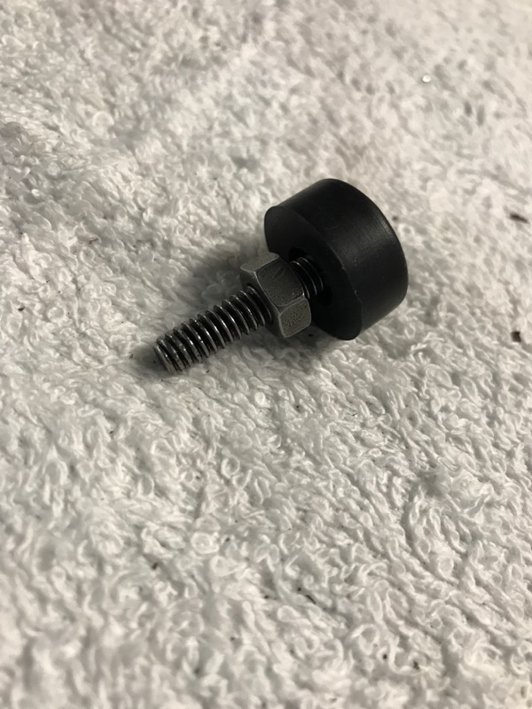
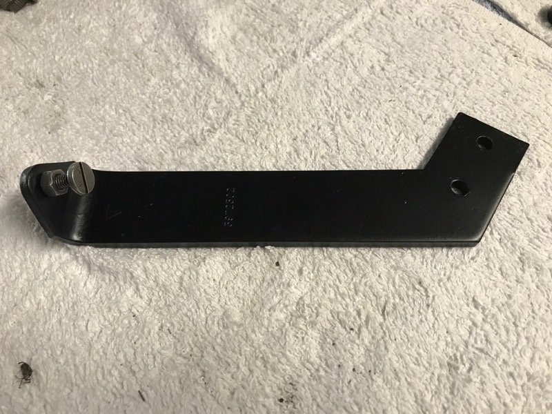
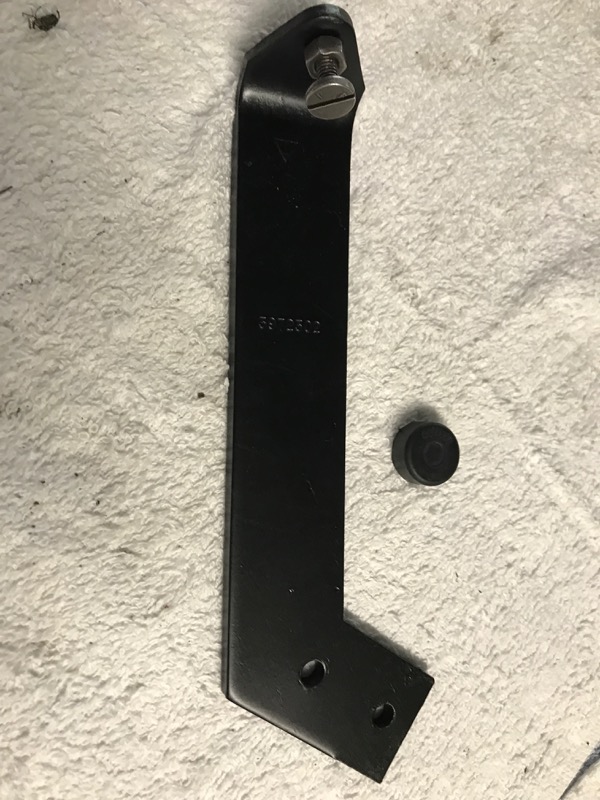
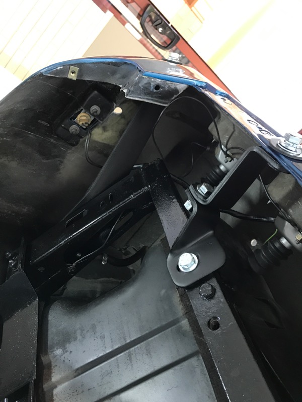
Fitted the headlight side bracket that controls the upper stop position.
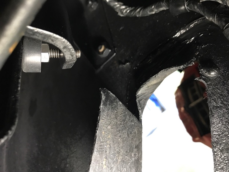
There is a threaded bump stop fitted with a rubber stop that gets adjusted so that it just hits prior to full mechanism extension. That way it locks in the upward position firmly with some slight compression of the rubber.
I tested it with my vacuum pump and the lights up then click and lock into a solid position.
There is no movement once in the upper position.
Once I am 100% happy I will wind down the locking bolt on the stop.
Last edited by CraigH; Apr 10, 2023 at 06:36 AM.
Corvette Stories
The Best of Corvette for Corvette Enthusiasts

Top 10 Most Expensive Corvettes Ever Sold on Bring A Trailer
Brett Foote
10 Things Every Corvette Owner Needs (2026 Edition)
Michael S. Palmer
8 Most "Only Corvette Owners Understand" Quirks and Problems
Pouria Savadkouei
10 Reasons the C6 Z06 is Still A Performance Benchmark After 20 Years
Joe Kucinski
How Much Horsepower Every Corvette Engine "LOST" in 1972
Joe Kucinski
Top 10 DOs and DON'Ts for Protecting Your Convertible Top!
Michael S. Palmer
Top 10 Most Explosive Corvettes Ever Made: Power-to-Weight Ratio Ranked!
Joe Kucinski
150 hp to 1,250 hp: Every Corvette Generation Compared by the Specs That Matter
Joe Kucinski
8 Coolest Corvette Pace Cars (and Replicas) of All Time
Verdad Gallardo

Thread Starter
Melting Slicks
Joined: Apr 2010
Posts: 2,795
Likes: 1,196
From: Canberra Australia
2025 C3 of the Year Finalist - Modified
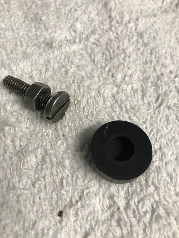
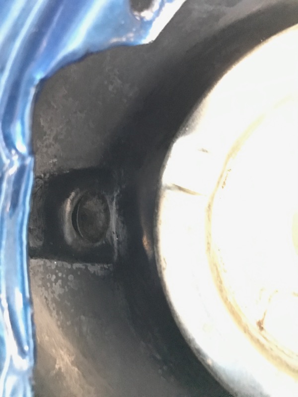
As an example for the main bumper brackets front and rear originally they used a solid washer with cerations on one side to bite into the steel. That is not part of the new kits that just include large washers, so I will be mixing old and new.
I just checked the bolts in the picture and they are not stainless, just new :-)
Last edited by CraigH; May 23, 2019 at 05:59 PM.


Thread Starter
Melting Slicks
Joined: Apr 2010
Posts: 2,795
Likes: 1,196
From: Canberra Australia
2025 C3 of the Year Finalist - Modified
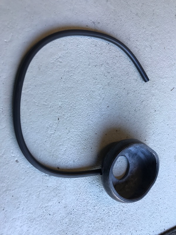
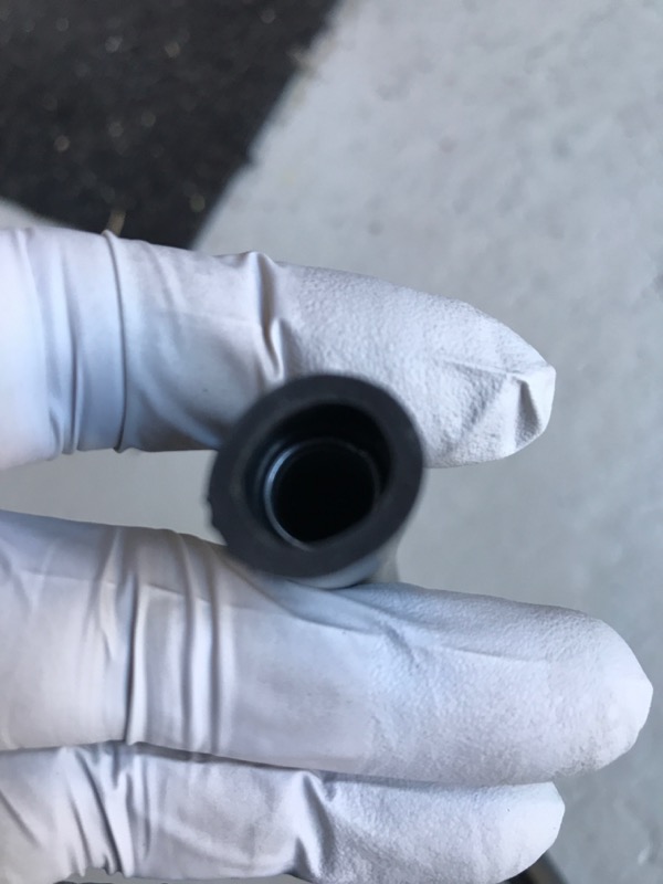
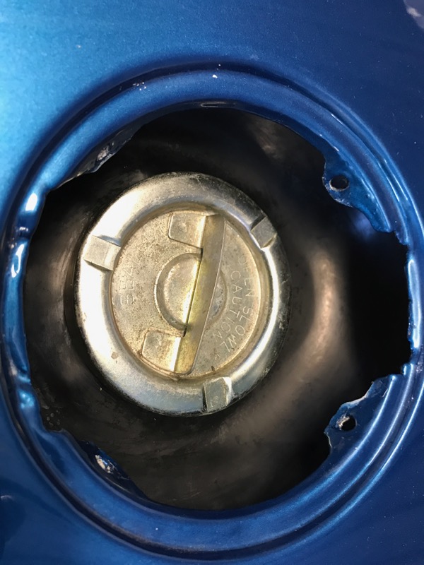
Prepared the fuel overflow tube with spring and installed on tank from top.
Last edited by CraigH; Apr 10, 2023 at 06:35 AM.

Thread Starter
Melting Slicks
Joined: Apr 2010
Posts: 2,795
Likes: 1,196
From: Canberra Australia
2025 C3 of the Year Finalist - Modified
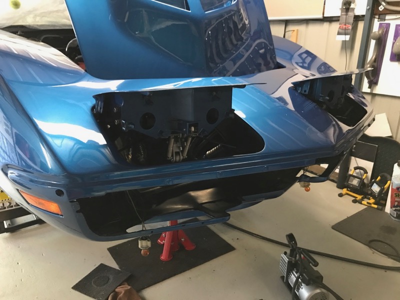
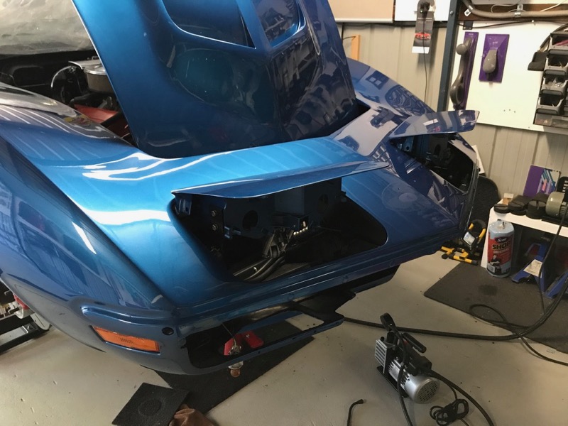
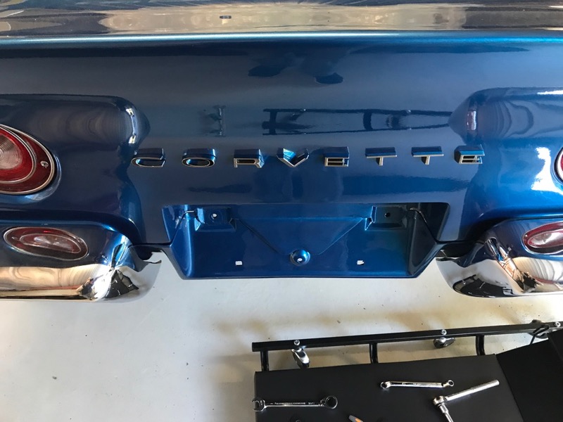
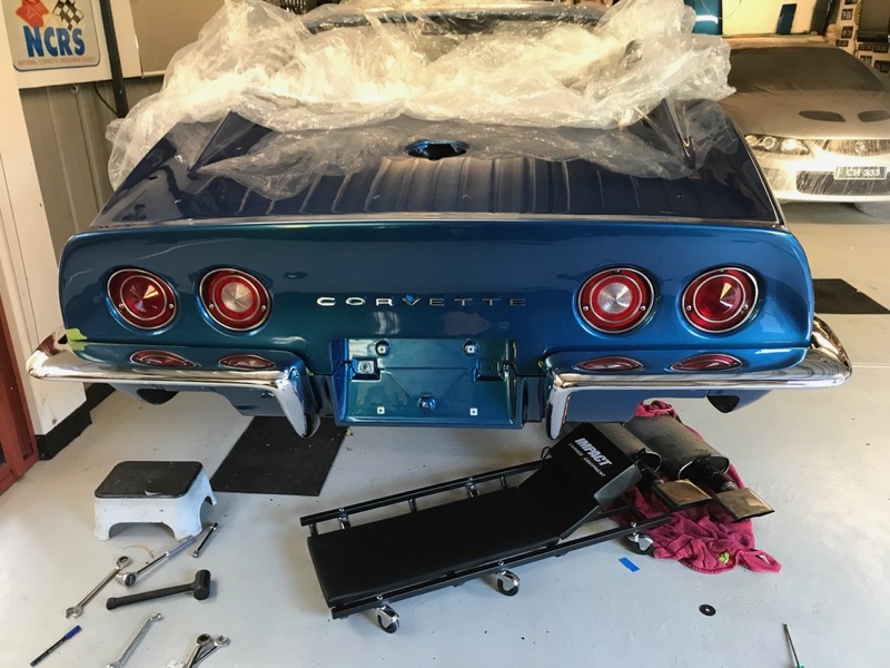
Rear valence on for a test fit and to work out what fasteners I need to find

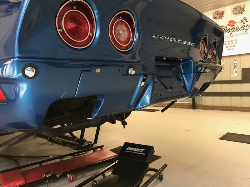
Also picked up a new floor creeper with head support.
Also picked up a new floor creeper with head support.
Last edited by CraigH; Apr 10, 2023 at 06:35 AM.

Thread Starter
Melting Slicks
Joined: Apr 2010
Posts: 2,795
Likes: 1,196
From: Canberra Australia
2025 C3 of the Year Finalist - Modified
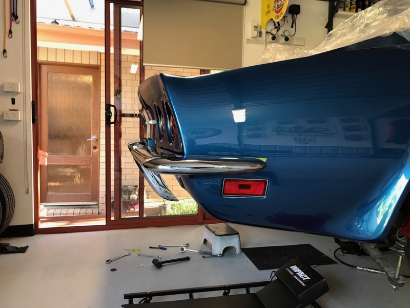
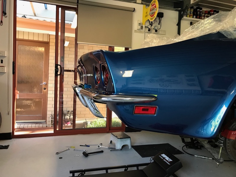
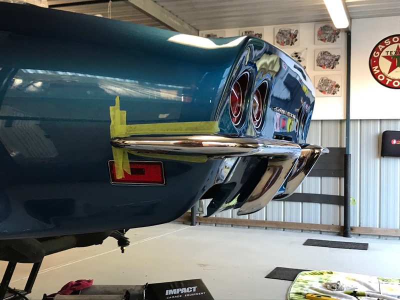
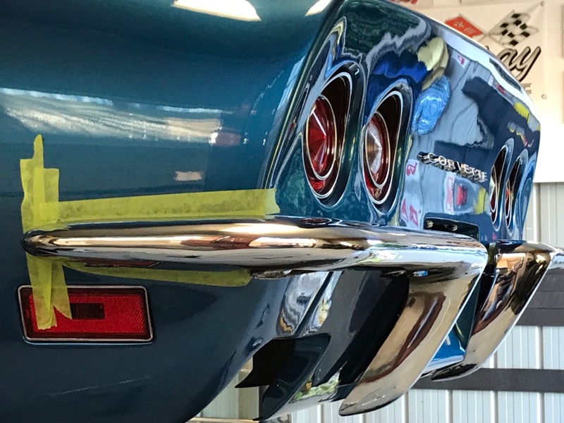
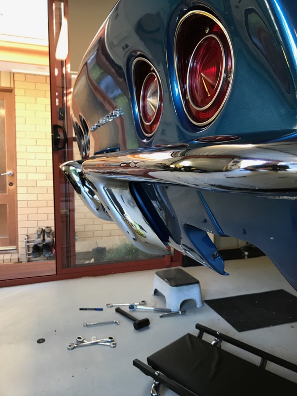
I test fitted my original rear bumpers to ensure it was all correct.
Bolted up perfectly, just slight adjustments needed.
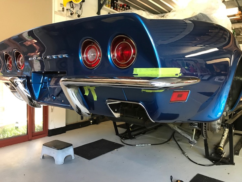
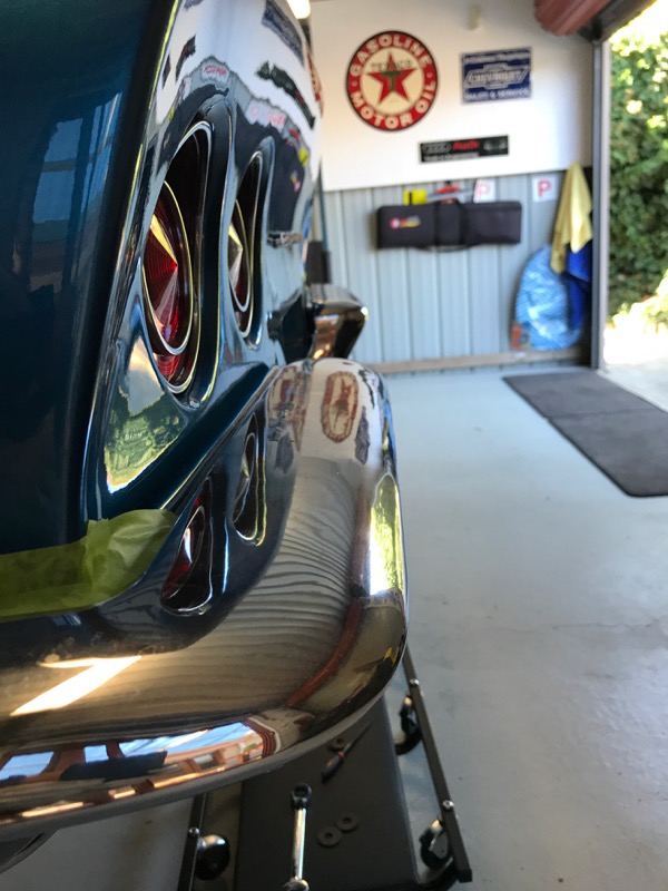
I have purchased some new rear bars but will decide on re chroming these based on the fit for the repos.
Bolted up perfectly, just slight adjustments needed.
I have purchased some new rear bars but will decide on re chroming these based on the fit for the repos.
Last edited by CraigH; Apr 10, 2023 at 06:34 AM.


Thread Starter
Melting Slicks
Joined: Apr 2010
Posts: 2,795
Likes: 1,196
From: Canberra Australia
2025 C3 of the Year Finalist - Modified
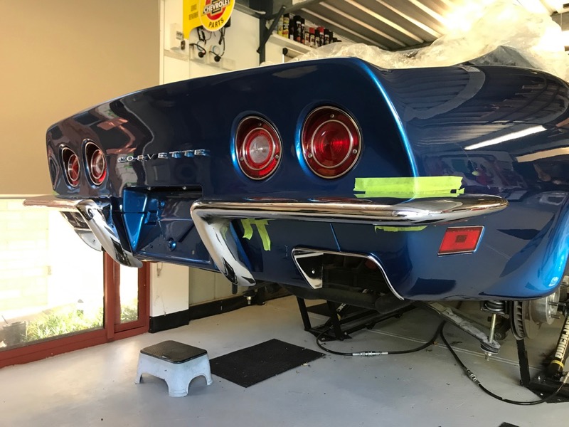
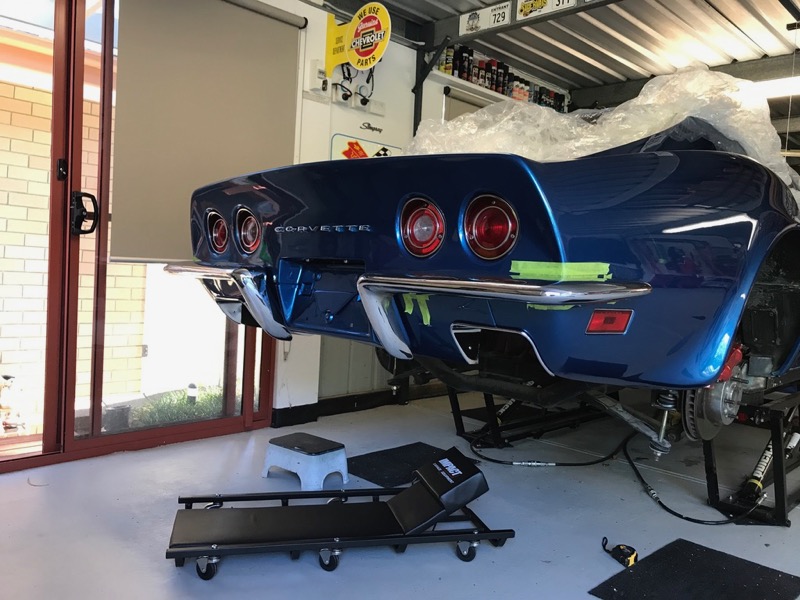
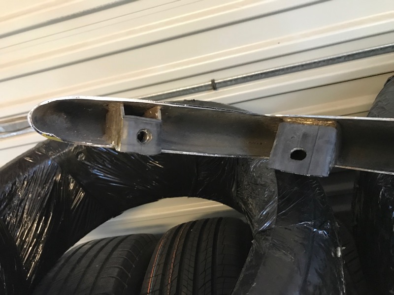
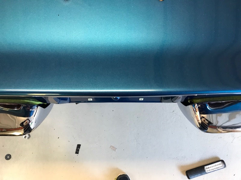
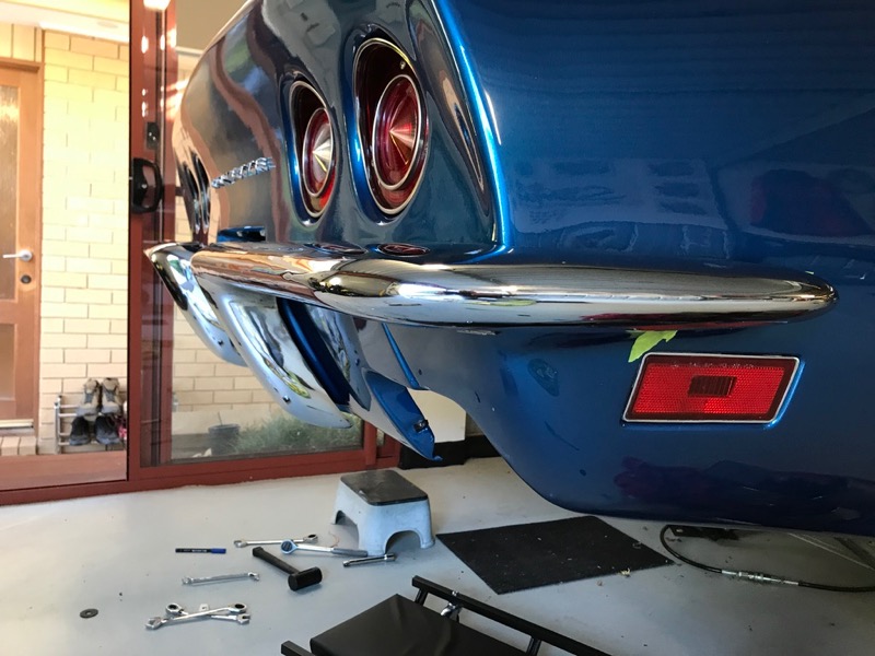
Second attempt to align rear bar.
This time without rear valence etc I addjusted the two inner bar mounts so they were parallel. This brought one side of the taillight panel in slightly and moved the other side out.
This gave me a good starting point.
I also went to 1mm thick rubber on each of the bumper mounts to protect the paint (previously it was 1.5mm.
Alignment was good.
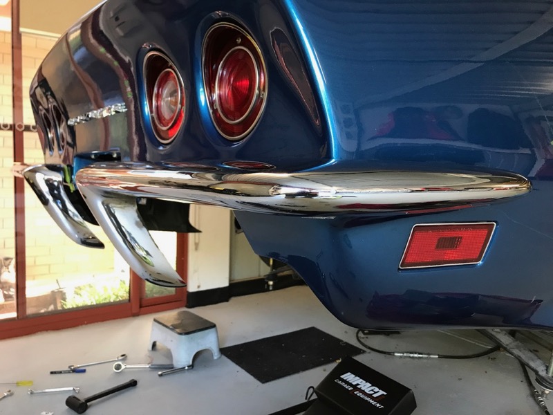


Ran the long level along and all looked good.
Test fitted the rear valence with 2 bolts to see how it then fitted.


To get it to fit nicely I ended up opening up some of the fibreglass holes slightly to ensure bolts did not tough at all as well as elongate most of the bar holes to give me enough movement to get it all where i wanted it.
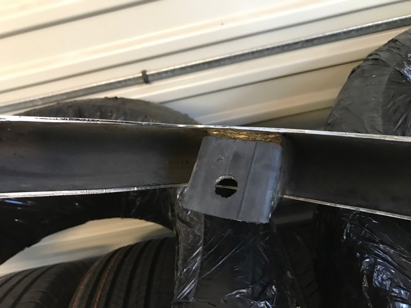
I also added some shims behind the two centre bar brackets so it sits flush on the glass with no bending pressure.
The side bolts have a 2.5" wide aluminium plate behind them to spread the load of the bolt when tightened as well.
This time without rear valence etc I addjusted the two inner bar mounts so they were parallel. This brought one side of the taillight panel in slightly and moved the other side out.
This gave me a good starting point.
I also went to 1mm thick rubber on each of the bumper mounts to protect the paint (previously it was 1.5mm.
Alignment was good.
Ran the long level along and all looked good.
Test fitted the rear valence with 2 bolts to see how it then fitted.
To get it to fit nicely I ended up opening up some of the fibreglass holes slightly to ensure bolts did not tough at all as well as elongate most of the bar holes to give me enough movement to get it all where i wanted it.
I also added some shims behind the two centre bar brackets so it sits flush on the glass with no bending pressure.
The side bolts have a 2.5" wide aluminium plate behind them to spread the load of the bolt when tightened as well.
Last edited by CraigH; Apr 10, 2023 at 06:34 AM.