


Bee Jay's Batwing install
Le Mans Master


Joined: Apr 2007
Posts: 7,353
Likes: 72
From: Graceland in a Not Correctly Restored Stingray

...but I might add a word of caution not to eliminate negative camber gain altogether by lowering the inner camber strut links so as to have the struts parallel with the 1/2 shafts. Parallel struts and 1/2 shafts may be the hot setup for the drag strip (where you want as near zero camber change in squat as is possible), but neg camber gain is still your friend for cornering. Worse yet would be dropping the inners beyond parallel to where positive camber gain will be induced in bump during squat or roll.
Going too far here can more than erase any benefit from having lowered the rear roll center. Until and unless I see a sound argument for doing so, I would suggest not lowering the inner links further than 0.5" below their OEM location relative to the diff (John Greenwood's long advised setup). FWIW, tho I do like the design of VB&P's bracket, even its highest adjustment (max neg camber gain) is beyond that point. correction - this last statement is inaccurate, as the highest adjustment apparently does meet the Greenwood spec.
I know it's easy for pics to present optical illusions, so I don't know exactly where you're at, but I didn't want to leave you hanging with this unsaid, just in case.

Last edited by TheSkunkWorks; Dec 31, 2008 at 02:21 PM. Reason: correction
Thread Starter
Safety Car


Joined: Nov 2005
Posts: 3,961
Likes: 573
From: Lompoc, CA. Santa Barbara County
Agree that it is coming together nicely...
...but I might add a word of caution not to eliminate negative camber gain altogether by lowering the inner camber strut links so as to have the struts parallel with the 1/2 shafts. Parallel struts and 1/2 shafts may be the hot setup for the drag strip (where you want as near zero camber change in squat as is possible), but neg camber gain is still your friend for cornering. Worse yet would be dropping the inners beyond parallel to where positive camber gain will be induced in bump during squat or roll.
Going too far here can more than erase any benefit from having lowered the rear roll center. Until and unless I see a sound argument for doing so, I would suggest not lowering the inner links further than 0.5" below their OEM location relative to the 1/2 shafts (John Greenwood's long advised setup). FWIW, tho I do like the design of VB&P's bracket, even its highest adjustment (max neg camber gain) is beyond that point.
I know it's easy for pics to present optical illusions, so I don't know exactly where you're at, but I didn't want to leave you hanging with this unsaid, just in case.
Le Mans Master
Joined: Apr 2007
Posts: 7,353
Likes: 72
From: Graceland in a Not Correctly Restored Stingray
I was afraid of that. Technically speaking, your instantaneous centers, or IC's (the point at which the respective CL's of the struts and 1/2 shafts converge) yield a virtual swing arm which hinges from a point to the outside of the wheel in question, resulting in positive camber gain in bump. You want this "hinge" point to be on the opposite side of the vehicle from the wheel in question so that you have negative camber gain in bump, else you'll end up with the top of the outside rear tire leaning out in corners. The length of this virtual swing arm determines the rate of camber gain during suspension travel.
FWIW, while parallel, equal length arms have no theoretical camber gain (great at the strip), with such a layout the camber of the rear tires relative to the ground changes in direct relation to the roll attitude of the chassis (not so good for anything else).
Hope that helps...
FWIW, while parallel, equal length arms have no theoretical camber gain (great at the strip), with such a layout the camber of the rear tires relative to the ground changes in direct relation to the roll attitude of the chassis (not so good for anything else).
Hope that helps...
Last edited by TheSkunkWorks; Dec 28, 2008 at 12:53 AM.
Thread Starter
Safety Car
Joined: Nov 2005
Posts: 3,961
Likes: 573
From: Lompoc, CA. Santa Barbara County
I was afraid of that. Technically speaking, your instantaneous centers, or IC's (the point at which the respective CL's of the struts and 1/2 shafts converge) yield a virtual swing arm which hinges from a point to the outside of the wheel in question, resulting in positive camber gain in bump. You want this "hinge" point to be on the opposite side of the vehicle from the wheel in question so that you have negative camber gain in bump, else you'll end up with the top of the outside rear tire leaning out in corners. The length of this virtual swing arm determines the rate of camber gain during suspension travel.
FWIW, while parallel, equal length arms have no theoretical camber gain (great at the strip), with such a layout the camber of the rear tires relative to the ground changes in direct relation to the roll attitude of the chassis (not so good for anything else).
Hope that helps...
FWIW, while parallel, equal length arms have no theoretical camber gain (great at the strip), with such a layout the camber of the rear tires relative to the ground changes in direct relation to the roll attitude of the chassis (not so good for anything else).
Hope that helps...
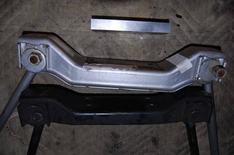
Here is an earlier picture before the batwing install, you can see that the distance between the rods and the shafts decreases toward the wheel.

In this picture, you can see the spacer I'll be removing. You can also see the four hole spring mount that has to replaced when you go to a batwing.

Last edited by Bee Jay; Dec 28, 2008 at 09:37 AM.
Thread Starter
Safety Car
Joined: Nov 2005
Posts: 3,961
Likes: 573
From: Lompoc, CA. Santa Barbara County
Dang Skunk. When you are right, you are right on. I removed the spacer under the strut rod mount tonight. That sucker was 3/4" thick. It was my attempt to make my own smart struts with my stock struts way back in the day. When I upgraded to heim struts, I kept the spacer, but the new mount had some drop built in. I mistakenly thought the more drop, the better. Anyways, after removing the spacer I measured the camber. I had slight negative camber at full drop, the same negative camber at ride height, and the same negative camber at full compression. What a difference. With the spacer in, I was going from negative camber at fi;; drp[ to positive camber at full up compression. I guess positive camber gain in compression is bad. My car will prolly handle amazingly better not just because of all the new stuff, but because I'm fixing so much that was wrong.
Here it is at full drop, only slight negative bubble:

Here it is at approxamate ride height, only slight negative bubble:

And here it is at full up compression. Only slight negative bubble.

I made sure both sides were about the same amount of bubble, and I buttoned everything up. The alignment shop can be more precise. The strut rods are much more parallel to the drive shafts now.
I still need to hang the exhaust, bleed the brakes, and grease the new u-joints.
Bee Jay
Here it is at full drop, only slight negative bubble:
Here it is at approxamate ride height, only slight negative bubble:
And here it is at full up compression. Only slight negative bubble.
I made sure both sides were about the same amount of bubble, and I buttoned everything up. The alignment shop can be more precise. The strut rods are much more parallel to the drive shafts now.
I still need to hang the exhaust, bleed the brakes, and grease the new u-joints.
Bee Jay
Last edited by Bee Jay; Apr 23, 2009 at 06:19 PM.
Le Mans Master
Joined: Apr 2007
Posts: 7,353
Likes: 72
From: Graceland in a Not Correctly Restored Stingray
Glad you're on the right track, but tho your camber now appears to be more or less constant relative to the chassis, bear in mind that when the chassis leans over during cornering, without provision for some compensatory neg camber gain in bump/compression so will the outside rear tire in relation to the ground. IMHO, virtual elimination of this gain is best left for C2/C3's intended for life at the drag strip, where squat during launch is the big issue. For the rest of us, I tend to side with Greenwood's recommendation to lower the inner strut 0.5" below the C3 OEM height (changes "D" height spec by -0.5") as the preferred default setting; alternatives proven thru testing aside.
Thread Starter
Safety Car
Joined: Nov 2005
Posts: 3,961
Likes: 573
From: Lompoc, CA. Santa Barbara County
I think I have the factory mount here somewhere. I will meausre the difference between it and this aftermarket mount. I bet it's more than 1/2". But I will take this as is. Removing the spacer was easy. Going back to the factory mount and rods is not an option. Once I get 295/35-18 tires mounted on my brand new in the box never used C5 Z06 10.5" rims on, constant negative camber thruout the travell will be satisfactory. I did mount up the 9.5" wheels and 275/40-18 tires to test the clearance with the new offsets. They are way out of the way now, and the frame is now definitely the limit. I mounted the bare 10.5" wheel to test clearnace, and I had a good 3/4" space from the frame and more than 1 1/2" clearance from the trailing arms. Of course this was all at full drop. I can't wait to ge the car down.
Bee Jay
Bee Jay
Corvette Stories
The Best of Corvette for Corvette Enthusiasts

150 hp to 1,250 hp: Every Corvette Generation Compared by the Specs That Matter
Joe Kucinski
8 Coolest Corvette Pace Cars (and Replicas) of All Time
Verdad Gallardo
Top 10 Corvette Engines RANKED by Peak Torque (70+ Years of Muscle!)
Joe Kucinski
Corvette ZR1X Will Be Pacing the Indy 500, And Could Probably Race, Too!
Verdad Gallardo
Top 10 Corvettes Coming to Mecum Indy 2026!
Brett Foote
Top 10 C9 Corvette MUST-HAVES to Fix These C8 Generation Flaws!
Michael S. Palmer
10 Revolutionary 'Corvette Firsts' Most People Don't Know
Joe Kucinski
5 Reasons to Upgrade to an LS6-Powered Corvette; 5 Reasons to Stay LT2
Michael S. Palmer
2027 Corvette vs The World: Every C8 vs Its Closest Competitor
Joe KucinskiLe Mans Master
Joined: Apr 2007
Posts: 7,353
Likes: 72
From: Graceland in a Not Correctly Restored Stingray
Just so you're aware of the option, you can always eliminate the factory bracket's eccentrics and keep your heim-jointed struts by fabbing up some "lock plates" such as come with most any kit...

However much further you decide to take this, in any event you should be well pleased with the improvements you've made during this nice project.
However much further you decide to take this, in any event you should be well pleased with the improvements you've made during this nice project.
Last edited by TheSkunkWorks; Dec 30, 2008 at 01:04 PM.


Thread Starter
Safety Car
Joined: Nov 2005
Posts: 3,961
Likes: 573
From: Lompoc, CA. Santa Barbara County
Just so you're aware of the option, you can always eliminate the factory bracket's eccentrics and keep your heim-jointed struts by fabbing up some "lock plates" such as come with most any kit...
However much further you decide to take this, in any event you should be well pleased with the improvements you've made during this nice project.
However much further you decide to take this, in any event you should be well pleased with the improvements you've made during this nice project.
Bee Jay
Thread Starter
Safety Car
Joined: Nov 2005
Posts: 3,961
Likes: 573
From: Lompoc, CA. Santa Barbara County
Check this out. The silver strut rod mount is from an early C2-C3, I'm not sure which year. The black strut rod mount is what came originally on my '79. The silver one mounts the rod ends 1/2" above the rear end bottom surface. The black one mounts the rod ends 1/2" below the rear end bottom surface. So GM moved the rod ends down 1" sometime in the C2-C3 production. The red strut rod of unknown orgin mounts the strut rods 2" below the rear end bottom. So with the 3/4" spacer, I was running the strut rods 2 3/4" below the rear end bottom. Wow! Anyone know how much the smart strut mount lowers the strut rod ends? This is all pretty interesting.
Bee Jay
Bee Jay
Le Mans Master
Joined: Jun 2002
Posts: 8,339
Likes: 24
From: I can walk to MA
Wow ... been gone for a long time and this is the first thread I stumble into.
Great work. The brackets look 100% pro. Nice welds.
The whole package looks even better.
Not sure about the geometry with lowering the strut rod mount.
Congrats
Great work. The brackets look 100% pro. Nice welds.
The whole package looks even better.
Not sure about the geometry with lowering the strut rod mount.
Congrats
Last edited by NHvette; Dec 31, 2008 at 12:09 AM.
Le Mans Master
Joined: Apr 2007
Posts: 7,353
Likes: 72
From: Graceland in a Not Correctly Restored Stingray
The camber strut bracket was revised with the introduction of the C3 chassis in '68, reducing camber gain and lowering rear roll center approximately 2". (C2 owners would do well to swap this piece out for the C3 one, IMHO.) Tho the earlier bracket may have induced excessive camber gain, that's not to say that all camber gain is bad, however.
VB&P's adjustable bracket moves the inner camber strut height down to from 1" to 1.75" below the diff/strut bracket mounting surface. That's a range of 0.50" to 1.25" below the OEM C3 height you've observed, and therefore I should correct myself by stipulating that their bracket DOES apparently meet the Greenwood height recommendation when setup in the higher (1" below diff) position. Note: When figuring ride height by suspension geometry, be sure to subtract the amount this point is lowered from "D" height being sought.
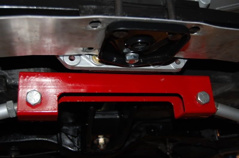
Again, the eccentrics reoriented by VB&P to provide quick camber gain adjustment (nice thought for street/strip cars) can be eliminated with camber lock plates, which can be custom fabbed for whatever desired height. On the down side, unless they've made revisions since my pointing it out some months ago, the mounting holes in the bracket are oversized, requiring bushing down for a better fit, as below...
Happy New Year
VB&P's adjustable bracket moves the inner camber strut height down to from 1" to 1.75" below the diff/strut bracket mounting surface. That's a range of 0.50" to 1.25" below the OEM C3 height you've observed, and therefore I should correct myself by stipulating that their bracket DOES apparently meet the Greenwood height recommendation when setup in the higher (1" below diff) position. Note: When figuring ride height by suspension geometry, be sure to subtract the amount this point is lowered from "D" height being sought.
Again, the eccentrics reoriented by VB&P to provide quick camber gain adjustment (nice thought for street/strip cars) can be eliminated with camber lock plates, which can be custom fabbed for whatever desired height. On the down side, unless they've made revisions since my pointing it out some months ago, the mounting holes in the bracket are oversized, requiring bushing down for a better fit, as below...
Happy New Year
Last edited by TheSkunkWorks; Dec 31, 2008 at 02:12 PM.

Safety Car
Joined: Aug 2006
Posts: 4,102
Likes: 1
From: Forsyth Illinois
BeeJay....what rearend are you using?I have heard that you can use the batwing on the earlier style rearends,and they will be fine,but like 1,or 2 bolts don't line up.I really like the idea here of lowering/moving the rearend up,but I have a perfect from on my 68,and the thought of cutting it makes me cring!
very nice work,and please comment on the rearend used.Thanks!
Great post!
very nice work,and please comment on the rearend used.Thanks!
Great post!
Thread Starter
Safety Car
Joined: Nov 2005
Posts: 3,961
Likes: 573
From: Lompoc, CA. Santa Barbara County
BeeJay....what rearend are you using?I have heard that you can use the batwing on the earlier style rearends,and they will be fine,but like 1,or 2 bolts don't line up.I really like the idea here of lowering/moving the rearend up,but I have a perfect from on my 68,and the thought of cutting it makes me cring!
very nice work,and please comment on the rearend used.Thanks!
Great post!
very nice work,and please comment on the rearend used.Thanks!
Great post!
Bee Jay

Safety Car
Joined: Aug 2006
Posts: 4,102
Likes: 1
From: Forsyth Illinois
Thanks for replying.And,looking forward to the pics.
My car isn't original,but very solid old girl.Cutting a perfectly good frame...well.....doesn't set well,but I want to get the rearend up alittle,and this is easiercthan whacking the frame up.Plus,I like the look of the batwing under the azzend of these cars.
Thanks,and may your new year be a blessed one.
VBD
And,looking forward to the pics.My car isn't original,but very solid old girl.Cutting a perfectly good frame...well.....doesn't set well,but I want to get the rearend up alittle,and this is easiercthan whacking the frame up.Plus,I like the look of the batwing under the azzend of these cars.
Thanks,and may your new year be a blessed one.
VBD
Thread Starter
Safety Car
Joined: Nov 2005
Posts: 3,961
Likes: 573
From: Lompoc, CA. Santa Barbara County
I had a frustrating day yesterday. I got home from work, hung the exhaust, and started the car. Fuel injection is great. The car has been up on the lift for months and it started right away. After I let the engine warm up a bit, I ease it into gear to let the drive train rotate slowly. Dang, something is hitting. The rear end is binding up somewhere, enough to make the wheels move up the suspension, then when the restriction is overcome, it unloads. Thats not good. I shut it off, shower and take the wife out dancing to bring the New Year in. I got up this morning and started searching for whats hitting. I can't see a thing, but it's hitting about twice every time the wheel turns. Maybe it's the parking brake or something in the new spindle in the trailing arm. I disconnect the axle shaft at the spindle. The spindle rotates freely. So it must be in the u-joints. I rotate the axle, and it rotates freely, but there is that bump again. So it must be on the right side. I disconnect the axle at the flange. The flange rotates freely, and now so does the axles. What the heck. Maybe the U-joints are binding. Maybe I bent some pins. So I disconnect the axles at the rear end. Now everything is rotating freely. The drive shaft and rear end, and both flanges. I inspect the u-joints a second and third time. I start assembling everything very carefully and checking for binding again, but the thump, thump, thump, returns, but only after everything is assembled, and it's very difficult to rotate the assmebly past the resisitance. I study it for a long while, rotating things slowly. I remove the drain plug to make sure its not interfering with the rear end gears. Nope. I must be missing something. AHA!, I see the problem. The top of the yoke is impacting the flange plate when the suspension is at full drop. Once the suspension is compressed a bit, the interference goes away. I guess the combo of the raised rear end, new trailing arms, and negative camber, just all piled up and made the lowest suspension position to much angle and caused interference. I need to grind some clearance so that I can rotate the drivetrain when the car is up on the lift. I put the wheels on the car, lower it, and drive it around the hood. I had to shower and go to the Mother-in-Laws for New Years Dinner. I need to hook up the rear sway bar, wash the car, clearance the yokes and flanges, and I'm cruising again. Hppy New Years everybody.
Bee Jay
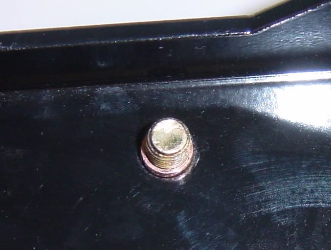
Here, you can see the yoke impacting the spindle flange plate:

I will have to clearance the impact spot, between the bolts, a little with my die grinder

Bee Jay
Here, you can see the yoke impacting the spindle flange plate:
I will have to clearance the impact spot, between the bolts, a little with my die grinder