


I got my 71 with the wipers not working and during an engine an trans rebuild I replaced the wiper motor while it was easy to get to. After getting the car back together the wipers were dead although the motor works fine when jumped.
I have visited old threads here and eventually replaced every part of the system. Switchs,relays,servos,vacuum lines etc. So I now know I have a wiring problem. Also I believed this to be a positve ground system & hot at all times thus working off of grounds to complete the circuit. Is this incorrect?
I just came across another thread that says the ground for the wipers often get mistaken for a starter wire and gets hooked to the battery terminal on the starter. I think this may be my problem and would explain why it is hot at all times.
Can anyone provide a picture of this wiper ground wire or any added input?
Thanks to all in Advance!
on the wiring diagram for my 70 the ground for the wiper goes from the wiper to the blower motor then to the ground on the battery...i can only guess if its the same for a 71.
Where on the wiper motor does the ground connect too? I too read that it goes through the blower motor ground and when I check for a ground at the wiper motor case there was none so I ran a new ground to it but it did not help and if the motor circuit is being completed by grounding it rather than a 12v postive system than a direct ground would make it run all the time. I guess I need to know for sure if it is a negative or positive groung circuit.
Willcox Corvette
Former Vendor
close
Jun 5, 2022
- Member SinceAug 2006
- LocationJeffersonville Indiana 812-288-7103
- Posts:76,656
- Veteran Field #1St. Jude Donor '08-'09-'10-'11-'12-'13-'14-'15
-
Likes:426
-
Liked:1,847 Times in 1,485 Posts
The ground connects to a brass terminal on the front of the wiper motor. The screw that holds this terminal is also one used to hold the washer pump in place.
I think the link below may help you. I don't know why none of this turned up on your search, I have done multiple post on this the past two years.
Go read this and them post again if you still can't figure this out.
Corvette Windshield Wiper Motor Wire Schematic 69-72 with test
(This has been updated to correct schematic. Errors in the original GM schematic were carried over to our earlier version. Changes brought up in this topic lead us to tear apart our test machine and re-trace the wire diagram as it should be and not what is indicated in the AIM or other GM publications). The schematic on this test page is now 100 percent correct.
http://willcoxcorvette.com/repairand...elp.php?hID=95
Willcox Inc.
Its not that they didn't come up but I didn't find what I needed. I have used the link and found the Wilcox diagram to be useful but in my case incomplete. I have many unanswered question. I am not familar with this setup on C3 Corvettes but I do turn a wrench for a living with a new American car dealer for the last 20 years and often enjoy electrical problems but this is the first time one has ever gotten me this frustrated.
I have the cowl removed since a new windsheild was just installed. Also I bought the car with the wipers not working and an Invoice found in the car shows that a New York Manhatann garage attempted to repair back in 1993 and failed. So anything could have happen since then.
Since the cowl is removed I have the firewall switch bypassed and since I show continuity across the tach monuted vac switch I have that unpluged becaue I was trying to trace it out one wire at a time and I was getting feedback or power on both wires.
Is there supose to be power at all time with the switch working on the ground side to complete the circuit? Also how is the park cycle controlled?

Timely thread, I am dealing with the exact same issue right now. I also found the Wilcox diagram helpful but found what I assume to be an error related to wire color (unless my car wiring is a one-off from the factory). No disrespect meant to Wilcox btw, someone please correct me if this is not the case. Funny thing is, the factory diagram I have shows the same wiring as the Wilcox diagram but it is not correct. Would be interested to know if any other 70 owners found the same issue or if my car truly is incorrect from the factory.
The Wilcox diagram shows wire 6 (black/white) going to ground and wire 7 (black) going to the switch. That is the opposite of the way my 70 is factory wired.
I am also getting power on the blue and yellow wires which according to the Wilcox guide means either an incorrect ground on the wiper motor or a faulty relay or switch. I have isolated the motor and it works fine but when everything is plugged in it does not. I checked the motor ground and it is fine, I even ran a new ground to it, still have the voltage feedback issue.
Now have replaced the wiper relay just to be safe and confirmed it is wired correctly, still have voltage feedback. Just got a new wiper switch and will install that today to see if somehow that takes care of it, will let you guys know what I find.
Corvette Stories
The Best of Corvette for Corvette Enthusiasts
Explore

10 Most Common Corvette Problems of the Last 20 Years!
Joe Kucinski
5 MOST and 5 LEAST Popular Corvette Model Years in History!
Joe Kucinski
2027 Corvette Buyer's Guide: Everything You Need to Know!
Joe Kucinski
10 Things C8 Corvette Owners Hate (But Won't Tell You)
Joe Kucinski
10 Best Corvettes Coming to Barrett-Jackson Palm Beach 2026!
Brett Foote
Every Corvette Grand Sport Explained! (C2, C4, C6, C7, & C8)
Joe Kucinski
Grand Sport & Grand Sport X Launch Alongside All-New 535hp LS6 V8!
Michael S. Palmer
5 Reasons Bad Drivers Crash & 5 Ways to Avoid a Costly Mistake!
Joe Kucinski
7 Bolt-On Upgrades From Extreme Online Store to Level Up Your C6 Corvette
Pouria Savadkouei
Crap, new switch in, still no operation, relay only trips for washer, not wipers.
Back to the drawing board..........going to reground the motor one more time just to be sure.
Back to the drawing board..........going to reground the motor one more time just to be sure.
Willcox Corvette
Former Vendor
close
Jun 5, 2022
- Member SinceAug 2006
- LocationJeffersonville Indiana 812-288-7103
- Posts:76,656
- Veteran Field #1St. Jude Donor '08-'09-'10-'11-'12-'13-'14-'15
-
Likes:426
-
Liked:1,847 Times in 1,485 Posts
71c3ls5,
I’ll try to explain some of this for you.
First make sure you are not testing with a volt meter and use a test light, if you use a volt meter the system will back feed voltage and use the meter as a ground. It will show low voltage at the wiper switch connection as well as the motor 1-3 connection.
The wiper system is not all that complex on your car.
The solenoid on the back of the tach from terminal to terminal will have continuity; it is just a basic electro magnet that operates a vacuum plunger inside.
So. . .With this in mind do the following.
Test the yellow wire for continuity and for a short at the 123 connector on the motor.
Test the yellow wire for 12 volts at the solenoid and at the number 2 connector in our diagram.
Next verify the ground on the motor. You can do this two ways, one is to run a new ground from the motor to the engine, or the other is to un-plug the ground from the motor and with your test light connected touch a hot wire and see if you light up.
Once you establish the black wire is a good ground or you run a new ground use this ground and your test light to see if you have power on the number 1 and 3 terminals at the motor. If you don’t light up, you’re good on to go on these wires so far.
Test the 1 and 3 green and light blue wires for continuity and a short. Test the light blue wire at both the switch and the solenoid and the green at the motor and the relay. If these two wires test fine the move forward.
Go to the relay, verify the ground on the relay, and verify the black wire from the relay to the wiper switch.
Make sure the ground wire is on the center dash cluster. If the ground wire is on, verify that the upper portion of the center dash bezel is not separated from the lower section, if the tiny area between the upper and lower section is broke, run a ground from the wiper switch screw to the ground terminal on the center dash bezel.
If the motor powers up on a bench, then there is no reason it should not power up in the car with the correct wiring.
If you verify all the wires in the system as I’ve described above with a bench tested motor you should not have any problems.
To answer your question, the motor is a two field motor, the red wire with a white strip is a hot all the time wire and the motor is hot all the time.
The parking mechanism is controlled by the motor pulling voltage off the motor power, so if the limit switch is open the motor will not park the arms on top of the wiper door.
The yellow wire is switched voltage and runs from the washer pump and wiper motor, to the bulk head connector, thru the fuse box, to the solenoid and then to the relay.
Buskey,
The schematic is correct; you’re looking at the connector from the wrong perspective. You’re looking at the connector in the wiring diagram from the terminal side and you have to look at it from the top side or wire side.
Willcox
The diagram shows a LB, B and DB wire at the switch, with the B wire going to the relay.
My car has LB, BW and DB at the switch with the BW wire going to the relay (not to ground).
The configuration on the relay is the same, looking from the top or wire side. In other words, the BW wire coming from the middle switch terminal goes to position 6 on the relay.
All wires are still in their 40-year-old factory harness.....??
Willcox Corvette
Former Vendor
close
Jun 5, 2022
- Member SinceAug 2006
- LocationJeffersonville Indiana 812-288-7103
- Posts:76,656
- Veteran Field #1St. Jude Donor '08-'09-'10-'11-'12-'13-'14-'15
-
Likes:426
-
Liked:1,847 Times in 1,485 Posts
The picture of the relay is from my 76k mile 70. and the schematic is from the 1969 AIM. I just checked the 70 AIM and it is the exact same way on the diagram.
What you are saying is that your black and white wire from the wiper switch is running to the number 6 connection on the relay? (I guess GM could have had some different, I've not seen one that I can remember).
Willcox
What you are saying is that your black and white wire from the wiper switch is running to the number 6 connection on the relay? (I guess GM could have had some different, I've not seen one that I can remember).
Willcox
Quote:
What you are saying is that your black and white wire from the wiper switch is running to the number 6 connection on the relay? (I guess GM could have had some different, I've not seen one that I can remember).
Willcox
Absolutely, the BW wire runs from center terminal on the wiper switch to 6 on the relay (I confirmed continuity), 7 on the relay is black and goes to ground (again, confirmed with continuity).Originally Posted by Willcox Corvette
The picture of the relay is from my 76k mile 70. and the schematic is from the 1969 AIM. I just checked the 70 AIM and it is the exact same way on the diagram. What you are saying is that your black and white wire from the wiper switch is running to the number 6 connection on the relay? (I guess GM could have had some different, I've not seen one that I can remember).
Willcox
Don't suppose you have a picture of the switch connector plugged in so I can confirm proper blue wire orientation? I am missing the switch plug, someone had put female spade terminals on the switch wires and plugged them onto the switch.
This is really killing me......only thing keeping me from putting the interior back together!
Buskey
Your post might as well be mine. My wiring configuration is the same as yours as I too noted the issue with the black wire with white tracer. My guess would be whatever is wrong with your car will be the same problem I am having. On your 123 connector on the wiper motor what color was the middle wire or starting from the closest to the passangers side going to the drivers side what was the color order. I beleive the last guy may have had moved these around inside the connector. Please keep me posted or PM me with any progress you may have and I will do the same.
Mr Wilcox
I thank you for your in depth repsonse and the time you have taken to give it. It seems to me I have gone through everything pretty much the way you described the process but still to no avail. I am going to print out your reply and go out to the shop and go over it one more time and report back
Test the yellow wire for continuity and for a short at the 123 connector on the motor. Test is Good and no Short.
[IMG] [/IMG]
Test the yellow wire for 12 volts at the solenoid and at the number 2 connector in our diagram.
With test light I have 12V
Next verify the ground on the motor. You can do this two ways, one is to run a new ground from the motor to the engine, or the other is to un-plug the ground from the motor and with your test light connected touch a hot wire and see if you light up.
Ground is good - Ran a new one
Once you establish the black wire is a good ground or you run a new ground use this ground and your test light to see if you have power on the number 1 and 3 terminals at the motor. If you don’t light up, you’re good on to go on these wires so far.
PROBLEM: I have power on 2&3 Yellow & blue but not #1
.
Test the 1 and 3 green and light blue wires for continuity and a short. Test the light blue wire at both the switch and the solenoid and the green at the motor and the relay. If these two wires test fine the move forward.
Test O.K.
Go to the relay, verify the ground on the relay, and verify the black wire from the relay to the wiper switch.
Ground is good. Used a jumper straight to switch
Here is what Buskey was saying it is the same on mine. The white with black tracer runs from the relay to the switch NOT the black wire. It is not shorted and continuity is good
[IMG] [/IMG]
[IMG] [/IMG]
Make sure the ground wire is on the center dash cluster. If the ground wire is on, verify that the upper portion of the center dash bezel is not separated from the lower section, if the tiny area between the upper and lower section is broke, run a ground from the wiper switch screw to the ground terminal on the center dash
[IMG]
[/IMG]Test the yellow wire for 12 volts at the solenoid and at the number 2 connector in our diagram.
With test light I have 12V
Next verify the ground on the motor. You can do this two ways, one is to run a new ground from the motor to the engine, or the other is to un-plug the ground from the motor and with your test light connected touch a hot wire and see if you light up.
Ground is good - Ran a new one
Once you establish the black wire is a good ground or you run a new ground use this ground and your test light to see if you have power on the number 1 and 3 terminals at the motor. If you don’t light up, you’re good on to go on these wires so far.
PROBLEM: I have power on 2&3 Yellow & blue but not #1
.
Test the 1 and 3 green and light blue wires for continuity and a short. Test the light blue wire at both the switch and the solenoid and the green at the motor and the relay. If these two wires test fine the move forward.
Test O.K.
Go to the relay, verify the ground on the relay, and verify the black wire from the relay to the wiper switch.
Ground is good. Used a jumper straight to switch
Here is what Buskey was saying it is the same on mine. The white with black tracer runs from the relay to the switch NOT the black wire. It is not shorted and continuity is good
[IMG]
[/IMG][IMG]
[/IMG]Make sure the ground wire is on the center dash cluster. If the ground wire is on, verify that the upper portion of the center dash bezel is not separated from the lower section, if the tiny area between the upper and lower section is broke, run a ground from the wiper switch screw to the ground terminal on the center dash
Here are a few more pictures that may help
[IMG] [/IMG]
[IMG] [/IMG]
[IMG] [/IMG]
[IMG]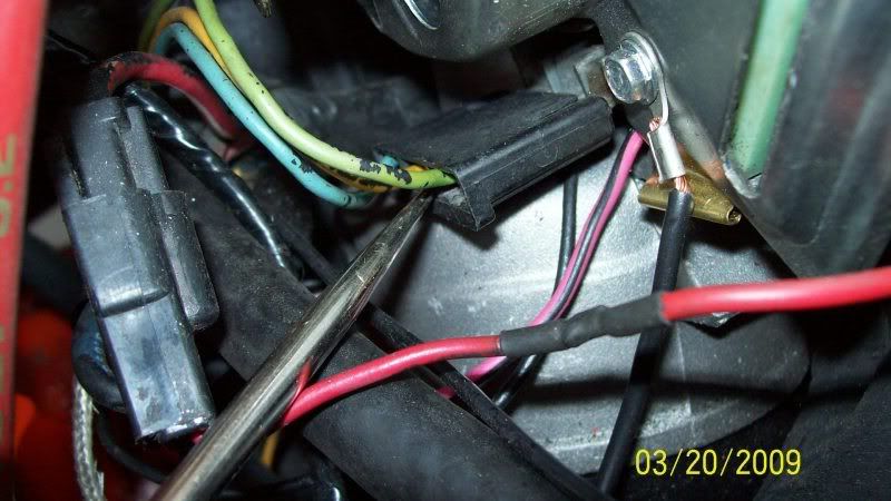 [/IMG]
[IMG] [/IMG]
[IMG]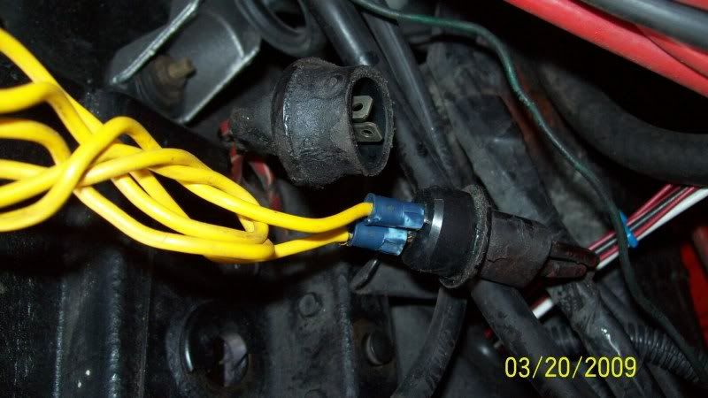 [/IMG]
[IMG]
[/IMG][IMG]
[/IMG][IMG]
[/IMG][IMG]
[/IMG][IMG]
[/IMG][IMG]
[/IMG]Also the 123 connector was not wired in the order shown. I changed it to reflect the wiring diagram that Wilcox provided. I can't remember now for sure where the previous owner had the wires but I think 2 & 3 were swapped
emccomas
Team Owner

close


Apr 20, 2026
- Member SinceMay 2005
- LocationHuntsville AL
- Posts:31,489
-
Likes:153
-
Liked:1,313 Times in 749 Posts
Pull the wiper switch out of the dash (which is easy) and run a temporary jumper wire (aligator clips on each end) from the wiper switch case to a good ground on the car. See if that makes any difference.
I have had this problem on three different C3s. The switch was not grounded properly. In all three cases I just made up a small ground wire from one of the screws that holds the switch to the bezel to a good grouind under the dash.
I have had this problem on three different C3s. The switch was not grounded properly. In all three cases I just made up a small ground wire from one of the screws that holds the switch to the bezel to a good grouind under the dash.
Quote:
Your post might as well be mine. My wiring configuration is the same as yours as I too noted the issue with the black wire with white tracer. My guess would be whatever is wrong with your car will be the same problem I am having. On your 123 connector on the wiper motor what color was the middle wire or starting from the closest to the passangers side going to the drivers side what was the color order. I beleive the last guy may have had moved these around inside the connector. Please keep me posted or PM me with any progress you may have and I will do the same.
Mr Wilcox
I thank you for your in depth repsonse and the time you have taken to give it. It seems to me I have gone through everything pretty much the way you described the process but still to no avail. I am going to print out your reply and go out to the shop and go over it one more time and report back
Glad I'm not going crazy after all (crazier? Originally Posted by 71C3LS5
BuskeyYour post might as well be mine. My wiring configuration is the same as yours as I too noted the issue with the black wire with white tracer. My guess would be whatever is wrong with your car will be the same problem I am having. On your 123 connector on the wiper motor what color was the middle wire or starting from the closest to the passangers side going to the drivers side what was the color order. I beleive the last guy may have had moved these around inside the connector. Please keep me posted or PM me with any progress you may have and I will do the same.
Mr Wilcox
I thank you for your in depth repsonse and the time you have taken to give it. It seems to me I have gone through everything pretty much the way you described the process but still to no avail. I am going to print out your reply and go out to the shop and go over it one more time and report back
 )! My thanks to Wilcox as well, I was totally lost without the diagram.
Can't really help with wire orientation, just realizing that not only am I missing the factory plug at the switch, it's also gone at the motor. The wires at each are connected individually. Your pictures really help, at least I know the proper order for the switch. Not sure how to orient them on the motor though (except for yellow in the center of course), is yours correct in the picture or is that what you were asking me?
Just getting back to t-shooting again now......will let you know how it goes. It's 2pm on Friday here....too early for a beer??? I just realized that is a really stupid question.....

Emccomas: Thanks for the input but I have the dash completly out of the car. I have a jumper wire on the switch straight to ground.
[IMG] [/IMG]
Update: While going through Mr. Wilcox's reply and re-running the test several times to be sure I am getting the correct results for no reason the motor starts running. It was going so fast I could not beleive that was a high speed selection but as I attempted to turn it off at the switch it only slowed down so I turned the key off and no change it continue to run and when I turn the key back on it goes back to 10000 RPM's. I checked the 123 connector while it was runing and there was no power at any of the three wires. I unpluged the relay and it just slowed down. I finally turn the bypass switch off and it shut down. Also as it was appearing to go crazy the washer pump randomly started and shut off and the drag of the pump caused it to slow sum but it would not shut off except to cut power from the red wire. This has got to be a result of previous attempt to repair this thing and perhaps a wire was spliced in the harness or another wire has melted the insulation off and burned into another wire causing the backfeed.
What is the possibility it is a bad motor? I am sure it was rebuilt in China or Mexico and the first 3 were doa. I have to keep walking away from it because I tend to have a bad temper and I afraid I may try to get even with this beast.
[IMG]
[/IMG]Update: While going through Mr. Wilcox's reply and re-running the test several times to be sure I am getting the correct results for no reason the motor starts running. It was going so fast I could not beleive that was a high speed selection but as I attempted to turn it off at the switch it only slowed down so I turned the key off and no change it continue to run and when I turn the key back on it goes back to 10000 RPM's. I checked the 123 connector while it was runing and there was no power at any of the three wires. I unpluged the relay and it just slowed down. I finally turn the bypass switch off and it shut down. Also as it was appearing to go crazy the washer pump randomly started and shut off and the drag of the pump caused it to slow sum but it would not shut off except to cut power from the red wire. This has got to be a result of previous attempt to repair this thing and perhaps a wire was spliced in the harness or another wire has melted the insulation off and burned into another wire causing the backfeed.
What is the possibility it is a bad motor? I am sure it was rebuilt in China or Mexico and the first 3 were doa. I have to keep walking away from it because I tend to have a bad temper and I afraid I may try to get even with this beast.