


Major Wiring Experts Needed!
Thread Starter
Race Director


Joined: Dec 2005
Posts: 13,515
Likes: 12
From: Fisher, IL
The more I keep adding to my car the more I realize I need to stop, re-due some stuff to make it simpler and safer.
I have:
1. Old fuse block that needs power
2. LS1 computer Needs power
3. Dual Spal Fans Need power
4. Dakota Digital wire block needs power.
Here's a picture of my current wire off the starter: with all the wires getting constant 12v. I combined it to just 2 terminals.
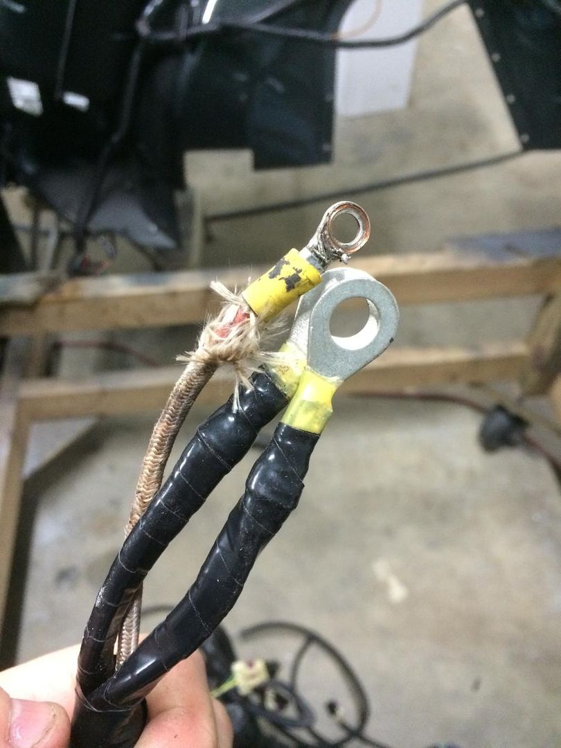
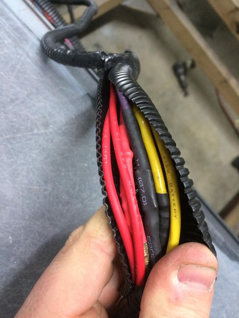
Here's all that's in there. minus the purple wire that goes to the other terminal on the starter.
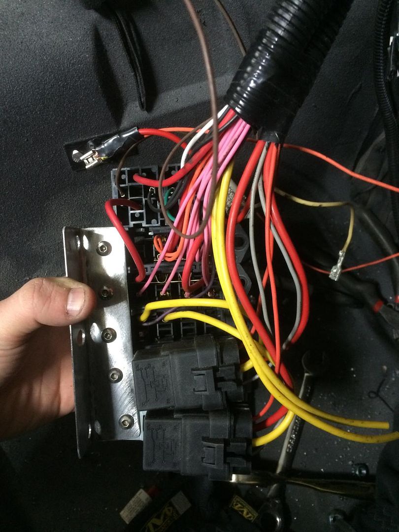
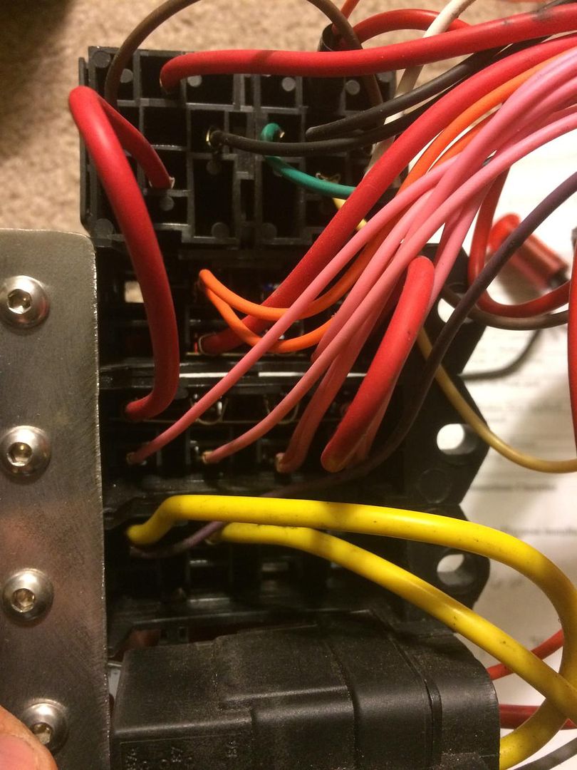
Here's the back of my LS1 fuse panel that I got an add on block to also do the fans/gauges.
My question is!!!!!
1. I know I could benefit from a power distribution block BUT what amp wire would I need to run to it from say the battery? How can I shield the connections at it? the ones I see usually are just an exposed post. I'd rather not have that inside anywhere for fear of something rubbing on it and sparking?
2. Since the car ran how it is currently wired(minus the gauges) I should probably just not mess with things. BUT I still need power to the gauges and am afraid of robbing 12v from wires not knowing how many amps they can handle from the starter post. I think most of the yellow ones are 10 gauge? maybe 12? and technically they're for the fans. But can I put them in a block and rob 12v off them for something else as well without overloading the wire?
Sorry for the crazy long post. I REALLY feel I would benefit from a distribution block. But that just means a TON more wiring after I spent a lot of time 2 years ago getting it like it is now lol.
I have:
1. Old fuse block that needs power
2. LS1 computer Needs power
3. Dual Spal Fans Need power
4. Dakota Digital wire block needs power.
Here's a picture of my current wire off the starter: with all the wires getting constant 12v. I combined it to just 2 terminals.

Here's all that's in there. minus the purple wire that goes to the other terminal on the starter.

Here's the back of my LS1 fuse panel that I got an add on block to also do the fans/gauges.

My question is!!!!!
1. I know I could benefit from a power distribution block BUT what amp wire would I need to run to it from say the battery? How can I shield the connections at it? the ones I see usually are just an exposed post. I'd rather not have that inside anywhere for fear of something rubbing on it and sparking?
2. Since the car ran how it is currently wired(minus the gauges) I should probably just not mess with things. BUT I still need power to the gauges and am afraid of robbing 12v from wires not knowing how many amps they can handle from the starter post. I think most of the yellow ones are 10 gauge? maybe 12? and technically they're for the fans. But can I put them in a block and rob 12v off them for something else as well without overloading the wire?
Sorry for the crazy long post. I REALLY feel I would benefit from a distribution block. But that just means a TON more wiring after I spent a lot of time 2 years ago getting it like it is now lol.
Burning Brakes

Joined: Oct 2008
Posts: 1,037
Likes: 14
From: Mobile Alabama
There are junction blocks with covers, here is an example
http://www.texasindustrialelectric.c...ion_blocks.asp
As far as wire size, it is a matter of adding all the load on that wire and selecting the correct size.
http://www.offroaders.com/tech/12-vo...gauge-amps.htm
http://www.texasindustrialelectric.c...ion_blocks.asp
As far as wire size, it is a matter of adding all the load on that wire and selecting the correct size.
http://www.offroaders.com/tech/12-vo...gauge-amps.htm
Thread Starter
Race Director
Joined: Dec 2005
Posts: 13,515
Likes: 12
From: Fisher, IL
There are junction blocks with covers, here is an example
http://www.texasindustrialelectric.c...ion_blocks.asp
As far as wire size, it is a matter of adding all the load on that wire and selecting the correct size.
http://www.offroaders.com/tech/12-vo...gauge-amps.htm
http://www.texasindustrialelectric.c...ion_blocks.asp
As far as wire size, it is a matter of adding all the load on that wire and selecting the correct size.
http://www.offroaders.com/tech/12-vo...gauge-amps.htm
According to the chart a 10 gauge wire going only 6-8ft can handle 150-200amps. So I should be WAY overkill for the fans. Enough to be able to rob power from them for the gauges.
Melting Slicks


Joined: Jan 2014
Posts: 2,478
Likes: 254
From: Downers Grove Illinois
The chart I looked at listed 55 amps as the maximum for chassis wiring for 10 gauge wire. Check the site here. Your gauges shouldn't draw much. The fans will be the big load and if your wiring already handles that adding the gauges to an existing wire shouldn't be an issue. See if you can borrow a clamp on DC ammeter to verify the load on the wiring if you are concerned.
Thread Starter
Race Director
Joined: Dec 2005
Posts: 13,515
Likes: 12
From: Fisher, IL
I read somewhere that the gauges only use less than an amp so I don't think there will be any issues.
Question. My LS1 wiring harness has two wires that say should go to "Ground side of Customer Supplied Fan Relay". Which are the two add on relays at the bottom of the picture.
Those relays have 4 sides:
-the yellow 10g to battery(I assume this is the positive side)
-the 10g red wire to the fans(Also positive as it contains power?)
-an orange wire that goes to the ignition.
-and a gray wire that goes to the temp sending unit.
Which of those is considered the ground?

Instructor

Joined: Jun 2014
Posts: 161
Likes: 0
From: Pensacola FL
Electric motors cause voltage irregularities during spin down. I could see a gauge getting some bounce or jitter to it anytime the fans kick on or off.
Burning Brakes
Joined: Oct 2008
Posts: 1,037
Likes: 14
From: Mobile Alabama
You can use the ECM to trigger the fans, or you can use a temp switch to turn on. Sounds like your gray wire is turning your fan off/on the way it is wired now. If you look on the bottom of the relay, 85 & 86 switch the relay. If you want the ECM to switch, you remove the gray (temp switch) off of 85 and connect the ECM wire. In this case 85 is the trigger as the ECM sends ground, 86 would be your orange ignition - or if you wanted it to run with the engine off, run it to battery.
30 & 87 are for the + high load. 87 to the fan + and 30 is the fused supply from battery.
30 & 87 are for the + high load. 87 to the fan + and 30 is the fused supply from battery.
Le Mans Master


Joined: Dec 2007
Posts: 6,422
Likes: 591
From: McHenry Illinois
If your computer is going to control the fans then you won't need the temp switches currently wired to the relays, that wire would hook up to the computer.
Oops, didn't type fast enough!
Oops, didn't type fast enough!
Corvette Stories
The Best of Corvette for Corvette Enthusiasts

Top 10 Most Expensive Corvettes Ever Sold on Bring A Trailer
Brett Foote
10 Things Every Corvette Owner Needs (2026 Edition)
Michael S. Palmer
8 Most "Only Corvette Owners Understand" Quirks and Problems
Pouria Savadkouei
10 Reasons the C6 Z06 is Still A Performance Benchmark After 20 Years
Joe Kucinski
How Much Horsepower Every Corvette Engine "LOST" in 1972
Joe Kucinski
Top 10 DOs and DON'Ts for Protecting Your Convertible Top!
Michael S. Palmer
Top 10 Most Explosive Corvettes Ever Made: Power-to-Weight Ratio Ranked!
Joe Kucinski
150 hp to 1,250 hp: Every Corvette Generation Compared by the Specs That Matter
Joe Kucinski
8 Coolest Corvette Pace Cars (and Replicas) of All Time
Verdad Gallardo
Race Director
Joined: Apr 2009
Posts: 19,294
Likes: 2,754
From: Charlotte NC
Those relays have 4 sides:
-the yellow 10g to battery(I assume this is the positive side)
-the 10g red wire to the fans(Also positive as it contains power?)
-an orange wire that goes to the ignition.
-and a gray wire that goes to the temp sending unit.
Which of those is considered the ground?
You would connect to the GRAY WIRE....that is your ground....BECAUSE...
the YELLOW 10g wire is the battery voltage going into your relay....and it is 'waiting' to go to the RED 10 g wire that goes to your fans......and KNOWING that the small gauge ORANGE WIRE is powered up when you turn your key on (which is 12 volts)....the ONLY other wire ....which pulls the coil in the relay and gets it to work as designed is the GRAY WIRE...which is your GROUND. Because the small ORANGE wire ( being 12 volts)...NEEDS the GRAY WIRE..(which is ground) to be grounded in order to pull the coil in the relay and make it compete the circuit so the YELLOW WIRES voltage is NOW going tote h RED 10g wire...and making your fans work.
I am wondering if the wires that you need to connect to these GRAY wires have something to do with internal switching...thus making the computer be able to control the fans....or if the computer needs to know when they come on.
DUB
Burning Brakes
Joined: Oct 2008
Posts: 1,037
Likes: 14
From: Mobile Alabama
DO you know and understand how a relay functions???? If not...hopefully this will help and it is the SAME for all 4 and 5 pin relays. 5 pin relays can do another circuit...but the coil works the same way.
You would connect to the GRAY WIRE....that is your ground....BECAUSE...
the YELLOW 10g wire is the battery voltage going into your relay....and it is 'waiting' to go to the RED 10 g wire that goes to your fans......and KNOWING that the small gauge ORANGE WIRE is powered up when you turn your key on (which is 12 volts)....the ONLY other wire ....which pulls the coil in the relay and gets it to work as designed is the GRAY WIRE...which is your GROUND. Because the small ORANGE wire ( being 12 volts)...NEEDS the GRAY WIRE..(which is ground) to be grounded in order to pull the coil in the relay and make it compete the circuit so the YELLOW WIRES voltage is NOW going tote h RED 10g wire...and making your fans work.
I am wondering if the wires that you need to connect to these GRAY wires have something to do with internal switching...thus making the computer be able to control the fans....or if the computer needs to know when they come on.
DUB
The LS has a temp sender in the head that goes to the ECM. The data is used for several controls, and the fans are one of them. You can change the programing for whatever temp you want, and there are two leads for two speeds or two fans - whatever way you set it up. But you dont have to have to use the ECM.
Thread Starter
Race Director
Joined: Dec 2005
Posts: 13,515
Likes: 12
From: Fisher, IL
DO you know and understand how a relay functions???? If not...hopefully this will help and it is the SAME for all 4 and 5 pin relays. 5 pin relays can do another circuit...but the coil works the same way.
You would connect to the GRAY WIRE....that is your ground....BECAUSE...
the YELLOW 10g wire is the battery voltage going into your relay....and it is 'waiting' to go to the RED 10 g wire that goes to your fans......and KNOWING that the small gauge ORANGE WIRE is powered up when you turn your key on (which is 12 volts)....the ONLY other wire ....which pulls the coil in the relay and gets it to work as designed is the GRAY WIRE...which is your GROUND. Because the small ORANGE wire ( being 12 volts)...NEEDS the GRAY WIRE..(which is ground) to be grounded in order to pull the coil in the relay and make it compete the circuit so the YELLOW WIRES voltage is NOW going tote h RED 10g wire...and making your fans work.
I am wondering if the wires that you need to connect to these GRAY wires have something to do with internal switching...thus making the computer be able to control the fans....or if the computer needs to know when they come on.
DUB
You would connect to the GRAY WIRE....that is your ground....BECAUSE...
the YELLOW 10g wire is the battery voltage going into your relay....and it is 'waiting' to go to the RED 10 g wire that goes to your fans......and KNOWING that the small gauge ORANGE WIRE is powered up when you turn your key on (which is 12 volts)....the ONLY other wire ....which pulls the coil in the relay and gets it to work as designed is the GRAY WIRE...which is your GROUND. Because the small ORANGE wire ( being 12 volts)...NEEDS the GRAY WIRE..(which is ground) to be grounded in order to pull the coil in the relay and make it compete the circuit so the YELLOW WIRES voltage is NOW going tote h RED 10g wire...and making your fans work.
I am wondering if the wires that you need to connect to these GRAY wires have something to do with internal switching...thus making the computer be able to control the fans....or if the computer needs to know when they come on.
DUB
Yeah... I never really took the time to sit back and learn how a relay works. I know the buzzer/flasher stuff I tried to learn confused me a little. Wire heating up and bending, bend enough it no longer makes contact and shuts off, back to bending again.... all so quickly? amazing lol.
Yeah. I never had the two fan wires hooked up before and everything worked okay. From what I'm reading they're for the computer to control the fans depending on if the AC(which I don't have) kicks on and what not. And probably what 74modified also suggested.
Not sure I'm even going to mess with hooking them up if all they do is control fan speed. If the fans on and spinning... I'll be happy. Or? should I hook them up?
Last edited by PUNISHER VETTE; Jan 29, 2015 at 08:15 PM.
Thread Starter
Race Director
Joined: Dec 2005
Posts: 13,515
Likes: 12
From: Fisher, IL
I have an even harder question I'm curious if anyone can answer:
The LS1 has the Temp sending unit which is currently being used by the PCM.
The Dakota Digital gauges sent their own water temp sending unit saying it MUST BE USED as all other sending units will supply the wrong data bla bla bla
Do I:
1. Use the empty port supplied on my LSx swap Dewitts radiator to add the sensor for the dakota gauges?
Or
2. Do I swap out the stock LS1 temp/pressure sensors with the Dakota one and splice in both the PCM and dakota wires together?
This also happens with the Oil pressure sensor. LS1 has one, Dakota requires theirs.
Last edited by PUNISHER VETTE; Jan 29, 2015 at 08:17 PM.
Burning Brakes
Joined: Oct 2008
Posts: 1,037
Likes: 14
From: Mobile Alabama
If it is working OK as-is you can leave it alone. The fan doesn't know where the power is coming from 
The ECM does add more sophisticated control. I am running a single fan, and the ECM turns on low speed at one temp and high speed at the next temp, or when A/C is on. You can do the same with twin fans and start them at different temps. You could do the same with temp switches, it just take more of them, and more wiring.
The ECM does add more sophisticated control. I am running a single fan, and the ECM turns on low speed at one temp and high speed at the next temp, or when A/C is on. You can do the same with twin fans and start them at different temps. You could do the same with temp switches, it just take more of them, and more wiring.
Burning Brakes
Joined: Oct 2008
Posts: 1,037
Likes: 14
From: Mobile Alabama
I have an even harder question I'm curious if anyone can answer:
The LS1 has the Temp sending unit which is currently being used by the PCM.
The Dakota Digital gauges sent their own water temp sending unit saying it MUST BE USED as all other sending units will supply the wrong data bla bla bla
Do I:
1. Use the empty port supplied on my LSx swap Dewitts radiator to add the sensor for the dakota gauges?
Or
2. Do I swap out the stock LS1 temp/pressure sensors with the Dakota one and splice in both the PCM and dakota wires together?
This also happens with the Oil pressure sensor. LS1 has one, Dakota requires theirs.
The LS1 has the Temp sending unit which is currently being used by the PCM.
The Dakota Digital gauges sent their own water temp sending unit saying it MUST BE USED as all other sending units will supply the wrong data bla bla bla
Do I:
1. Use the empty port supplied on my LSx swap Dewitts radiator to add the sensor for the dakota gauges?
Or
2. Do I swap out the stock LS1 temp/pressure sensors with the Dakota one and splice in both the PCM and dakota wires together?
This also happens with the Oil pressure sensor. LS1 has one, Dakota requires theirs.
Thread Starter
Race Director
Joined: Dec 2005
Posts: 13,515
Likes: 12
From: Fisher, IL
Nevermind. Looks like Dakota Offers a OBDII modular for $100 that gets most of the information it needs from the PCM. I'll just get that and not have to worry about wiring up all the sensors.
I guess I'll hook up the fan wires now that I know which ones they hook to. Won't take me too long and might be nice later on I guess
Thanks!
I guess I'll hook up the fan wires now that I know which ones they hook to. Won't take me too long and might be nice later on I guess
Thanks!
Burning Brakes
Joined: Oct 2008
Posts: 1,037
Likes: 14
From: Mobile Alabama
Nevermind. Looks like Dakota Offers a OBDII modular for $100 that gets most of the information it needs from the PCM. I'll just get that and not have to worry about wiring up all the sensors.
I guess I'll hook up the fan wires now that I know which ones they hook to. Won't take me too long and might be nice later on I guess
Thanks!
I guess I'll hook up the fan wires now that I know which ones they hook to. Won't take me too long and might be nice later on I guess
Thanks!
Thread Starter
Race Director
Joined: Dec 2005
Posts: 13,515
Likes: 12
From: Fisher, IL
Although they were expensive I really wanted LED gauges that looked better than the stock ones that people just add brighter lightbulbs to.

Last edited by PUNISHER VETTE; Jan 29, 2015 at 08:47 PM.
Thread Starter
Race Director
Joined: Dec 2005
Posts: 13,515
Likes: 12
From: Fisher, IL
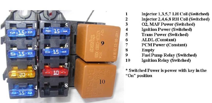
Can someone explain this to me.
PSI uses a 30amp relay(#10) to power fuses #1-5.
The fuses total to way more than 30amps.
So did they do this knowing the 5 fuses won't draw that much. Or is there something about the 30amp relay that I'm not understanding how much it can handle?
I'd like to add one or two more fuses to the switched power from that relay but don't want to overload it.

Race Director
Joined: Apr 2009
Posts: 19,294
Likes: 2,754
From: Charlotte NC
Are you POSITIVE that the #10 relay is doing as you wrote???
Do you have schematic of the wiring of this fuse/relay panel??? I need to see what is going on 'behind' this assembly.
I am guessing that you are using HEATED O2 sensors????
Fuse #4...is not making any sense....due to not seeing how it is being wired up.
NOT wanting to step on any toes...but I just got finished with a MAJOR wiring job on a LS equipped Corvette. AND if you want any help...I will be more than glad in aiding you..even as far as drawing out the schematic. The choice is yours...just PM me if interested so I know what you are wanting to do.
DUB
Thread Starter
Race Director
Joined: Dec 2005
Posts: 13,515
Likes: 12
From: Fisher, IL
Thanks
Here's a drawing I did quickly yesterday when I started working on all this. Basically the switched wire from the ignition relay powers all 5 fuses. which total to 80 amps worth of fuses.

I ordered the computer/wiring harness from PSI a year ago and just threw things together to see if I could get it running(which it did).
BUT...now that i have everything out and trying to get everything working(gauges, fans, ...) and looking more closely at how i wired things i'm starting to question some things.
1. I stole power for the switched connections from the blank IGN plug in the stock fuse block. Which I just figured out today is a mooched connection with the tail lights/running lights on a 20A fuse. If I'm running the PSI 30amp relay, and a few other things that need a "switched" connection i'm worried i'll overload that taillight fuse.
The gauges need 12v constant and switched still that I have to put in that fuse block somewhere. The 12v constant is easy as I have plenty of 12v wires coming off the starter with enough gauge thickness to handle what I have left to wire up. But switched power... I only have the PSI relay giving me switched power.
Here's a drawing I did quickly yesterday when I started working on all this. Basically the switched wire from the ignition relay powers all 5 fuses. which total to 80 amps worth of fuses.


I ordered the computer/wiring harness from PSI a year ago and just threw things together to see if I could get it running(which it did).
BUT...now that i have everything out and trying to get everything working(gauges, fans, ...) and looking more closely at how i wired things i'm starting to question some things.
1. I stole power for the switched connections from the blank IGN plug in the stock fuse block. Which I just figured out today is a mooched connection with the tail lights/running lights on a 20A fuse. If I'm running the PSI 30amp relay, and a few other things that need a "switched" connection i'm worried i'll overload that taillight fuse.
The gauges need 12v constant and switched still that I have to put in that fuse block somewhere. The 12v constant is easy as I have plenty of 12v wires coming off the starter with enough gauge thickness to handle what I have left to wire up. But switched power... I only have the PSI relay giving me switched power.
Last edited by PUNISHER VETTE; Feb 1, 2015 at 05:59 PM.