


Race Car Engine Build
Thread Starter
Le Mans Master


Joined: Oct 2007
Posts: 9,702
Likes: 3,472
From: Akron Ohio
2025 Corvette of the Year Finalist - Modified
2024 C5 of the Year Winner - Modified
2023 C5 of the Year Finalist - Modified
2022 C5 of the Year Finalist - Modified
St. Jude Donor '09-'10-'11
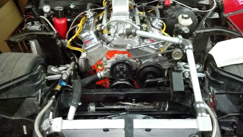
I have been super busy on other things lately but here are some pictures of my coolant tubes. I just cut the OEM hoses and put the the tubes in where they needed to go. All the wiring is done, just need to finish the dash and install gauges before trying to start it.
Lower

Upper

Front view
Lower
Upper
Front view
Race Director

Joined: Apr 2000
Posts: 15,344
Likes: 4,009
From: Texas
 I'm assuming you added a "ridge" inside of each end of the tube in order to ensure hose retention?
Safety Car


Joined: Apr 2011
Posts: 3,660
Likes: 22
Looks good !
Its nice to see someone else with the same approach... I elimenated 90% of the hose on my street Vette long ago. All it took was blowing an inacessable hose in the middle of nowhere and I saw the light. Even got a flushing adaptor built in, that doubles as a purge/air vent.
BTW,.
the build looks as professional as any I've seen. Good looking engine bay...looking forward to hearing about the "trials".
Good luck
Thread Starter
Le Mans Master
Joined: Oct 2007
Posts: 9,702
Likes: 3,472
From: Akron Ohio
2025 Corvette of the Year Finalist - Modified
2024 C5 of the Year Winner - Modified
2023 C5 of the Year Finalist - Modified
2022 C5 of the Year Finalist - Modified
St. Jude Donor '09-'10-'11
For the tubing, I made my own bead tool since I didnt want to spend a ton on a bead roller. The reason I didn't post a picture at first was because it doesn't look very good, but it is functional.
Don't make fun of it too much...


Thread Starter
Le Mans Master
Joined: Oct 2007
Posts: 9,702
Likes: 3,472
From: Akron Ohio
2025 Corvette of the Year Finalist - Modified
2024 C5 of the Year Winner - Modified
2023 C5 of the Year Finalist - Modified
2022 C5 of the Year Finalist - Modified
St. Jude Donor '09-'10-'11
 I knew I shouldn't have posted that...
Corvette Stories
The Best of Corvette for Corvette Enthusiasts

Every 2027 Corvette Engine Explained
Joe Kucinski
Designer Imagines A Corvette That Looks More Like a Corvette Than the Corvette
Verdad Gallardo
10 Ugly Corvettes That We Still Kinda Love
Joe Kucinski
Top 10 Most Expensive Corvettes Ever Sold on Bring A Trailer
Brett Foote
10 Things Every Corvette Owner Needs (2026 Edition)
Michael S. Palmer
8 Most "Only Corvette Owners Understand" Quirks and Problems
Pouria Savadkouei
10 Reasons the C6 Z06 is Still A Performance Benchmark After 20 Years
Joe Kucinski
How Much Horsepower Every Corvette Engine "LOST" in 1972
Joe Kucinski
Top 10 DOs and DON'Ts for Protecting Your Convertible Top!
Michael S. Palmer
Max G�s


Joined: Nov 2008
Posts: 2,751
Likes: 79
From: Monroe OH
NCM Sinkhole Donor
Looks good. When will you be able to get it on the dyno? I am interested in seeing the numbers with your air intake. Do you figure to have more cooler air when drawing in from this point vs from the nose area? Also, when they weigh the cars for your power to weight ratio, does the car weight include the driver?
Race Director
Joined: Apr 2000
Posts: 15,344
Likes: 4,009
From: Texas
 How can you forget the most important hp device....stickers
Thread Starter
Le Mans Master
Joined: Oct 2007
Posts: 9,702
Likes: 3,472
From: Akron Ohio
2025 Corvette of the Year Finalist - Modified
2024 C5 of the Year Winner - Modified
2023 C5 of the Year Finalist - Modified
2022 C5 of the Year Finalist - Modified
St. Jude Donor '09-'10-'11


Looks good. When will you be able to get it on the dyno? I am interested in seeing the numbers with your air intake. Do you figure to have more cooler air when drawing in from this point vs from the nose area? Also, when they weigh the cars for your power to weight ratio, does the car weight include the driver?
The reason for the rear facing intake is to take advantage of the high pressure area in the cowl. At speed it creates a ram air effect. The class I was originally building for had strict rules, and in a nut shell I was not allowed any forward facing holes that provided air to the intake. This way is not forward facing, but I get the same benefit. Now that class has been changed and I can do pretty much anything so its not needed, but still cool.
When NASA weighs the cars competition weight includes the driver, all gear, and any fuel in tank when finishing the race.
Thread Starter
Le Mans Master
Joined: Oct 2007
Posts: 9,702
Likes: 3,472
From: Akron Ohio
2025 Corvette of the Year Finalist - Modified
2024 C5 of the Year Winner - Modified
2023 C5 of the Year Finalist - Modified
2022 C5 of the Year Finalist - Modified
St. Jude Donor '09-'10-'11
I started making a template for the dash today. Believe it or not that one piece of poster board took several hours to make.
 Now I need to lay out my gauges and cut it out of aluminum.

This is what I hope the final product will look like:

Now I need to lay out my gauges and cut it out of aluminum.This is what I hope the final product will look like:
Thread Starter
Le Mans Master
Joined: Oct 2007
Posts: 9,702
Likes: 3,472
From: Akron Ohio
2025 Corvette of the Year Finalist - Modified
2024 C5 of the Year Winner - Modified
2023 C5 of the Year Finalist - Modified
2022 C5 of the Year Finalist - Modified
St. Jude Donor '09-'10-'11
The stickers go outside the car.


