


C4 front mount with a Lenco

Thread Starter
Racer


Joined: Jul 2004
Posts: 315
Likes: 15
From: Ornskoldsvik
/Svante
Thread Starter
Racer
Joined: Jul 2004
Posts: 315
Likes: 15
From: Ornskoldsvik
Does anyone know how much force the C-beam has to handle? My guess is that it does'nt need to handle much more than to align the tranny and the rear axle, all the twisting and bending is taken up by the engine mounts and rear end bushings. But im not sure! Im in the process of rebuilding the c-beam to the lenco and need to know how solid it need to be.
Thanks
/Svante
Thanks
/Svante

Melting Slicks


Joined: Sep 2003
Posts: 2,270
Likes: 118
From: N. Babylon NY
Does anyone know how much force the C-beam has to handle? My guess is that it does'nt need to handle much more than to align the tranny and the rear axle, all the twisting and bending is taken up by the engine mounts and rear end bushings. But im not sure! Im in the process of rebuilding the c-beam to the lenco and need to know how solid it need to be.
Thanks
/Svante
Thanks
/Svante


Last edited by STEVEN13; Oct 29, 2014 at 10:26 PM.
Thread Starter
Racer
Joined: Jul 2004
Posts: 315
Likes: 15
From: Ornskoldsvik
/Svante
Melting Slicks
Joined: Sep 2003
Posts: 2,270
Likes: 118
From: N. Babylon NY
Its overkill for me as my engine is stock right now. We were gonna modify the stock C-Beam-But the fabricator just made a new one. It came out great and is not too heavy.
Looking forward to see what you come up with.

Steve
Looking forward to see what you come up with.
Steve
Team Owner


Joined: Mar 2001
Posts: 30,856
Likes: 293
From: Boston, Dallas, Detroit, SoCal, back to Boston MA
a couple of things going on
act as the rear engine mount.
Need to help take engine torque
It keeps the pinion from rotating (plenty of snapped pinions out there)
It also anchors the rear suspension
act as the rear engine mount.
Need to help take engine torque
It keeps the pinion from rotating (plenty of snapped pinions out there)
It also anchors the rear suspension
Team Owner

Joined: Aug 2004
Posts: 21,543
Likes: 3,216
From: Park City Utah
2. no
3. yes (this is the major force that the C-beam deals with)
4. No. Not meaningfully.
On a stock C4 the most force the C-beam could have to deal with is in a ZR-1 and that would be up to ~3500 ft lbs. (375 eng tq x 2.681st gear x 3.45 axle ratio =3468
Read more about the C-Beam right HERE
Team Owner
Joined: Aug 2004
Posts: 21,543
Likes: 3,216
From: Park City Utah
The hard part could be to modify the c-beam to connect the Lenco to the rear....Does anyone know how much force the C-beam has to handle? My guess is that it does'nt need to handle much more than to align the tranny and the rear axle, all the twisting and bending is taken up by the engine mounts and rear end bushings. But im not sure! Im in the process of rebuilding the c-beam to the lenco and need to know how solid it need to be.
Thanks
/Svante
Thanks
/Svante
1. If you are going to use the C-beam to manage the diff torque (like a torque arm) as it does in a stock C4, then the C-beam will have to manage a lot of force (see my post above, where force= engine tq x 1st gear x diff ratio).
2. If you have a solid rear w/a 4 link then all the C-beam has to do is hold up the rear of the trans/engine assy...but in this case, you can't ALSO connect it to the rear.
What is your rear comprised of?
Last edited by Tom400CFI; Oct 31, 2014 at 02:11 PM.
Corvette Stories
The Best of Corvette for Corvette Enthusiasts

Top 10 Most Expensive Corvettes Ever Sold on Bring A Trailer
Brett Foote
10 Things Every Corvette Owner Needs (2026 Edition)
Michael S. Palmer
8 Most "Only Corvette Owners Understand" Quirks and Problems
Pouria Savadkouei
10 Reasons the C6 Z06 is Still A Performance Benchmark After 20 Years
Joe Kucinski
How Much Horsepower Every Corvette Engine "LOST" in 1972
Joe Kucinski
Top 10 DOs and DON'Ts for Protecting Your Convertible Top!
Michael S. Palmer
Top 10 Most Explosive Corvettes Ever Made: Power-to-Weight Ratio Ranked!
Joe Kucinski
150 hp to 1,250 hp: Every Corvette Generation Compared by the Specs That Matter
Joe Kucinski
8 Coolest Corvette Pace Cars (and Replicas) of All Time
Verdad GallardoTeam Owner
Joined: Aug 2004
Posts: 21,543
Likes: 3,216
From: Park City Utah
The batwing is a component there, yes, but a minor one. The batwing primarily stops the torque from causing any rotation imparted on the diff from the engine/trans, which is resolved through the frame rails. IOW, if you're looking at the diff from the rear of the car, under max acceleration in 1st gear, a ZR-1 will send 1005 lb of torque down the driveshaft and into the diff, trying to twist that diff CCW as viewed from the rear. The batwing transmits that force into the frame and up to the motor mounts.
Viewed from the driver's side and at the same moment of max acceleration, the diff housing wants to rotate CW on the axis of the stub axles, with that same tq, times the diff ratio, in a ZR-1's case 1005 x 3.45 which gets you ~3500 lb ft. Since the rear mount of the diff is the batwing and very close to that pivot point, the other "point" is the front motor mounts. The C-beam, trans and engine are the lever arm that prevent the diff from rotating the way it wants to as viewed from the side.
Viewed from the driver's side and at the same moment of max acceleration, the diff housing wants to rotate CW on the axis of the stub axles, with that same tq, times the diff ratio, in a ZR-1's case 1005 x 3.45 which gets you ~3500 lb ft. Since the rear mount of the diff is the batwing and very close to that pivot point, the other "point" is the front motor mounts. The C-beam, trans and engine are the lever arm that prevent the diff from rotating the way it wants to as viewed from the side.
Last edited by Tom400CFI; Nov 1, 2014 at 12:01 AM.
Melting Slicks


Joined: Oct 2000
Posts: 2,158
Likes: 9
From: N.E. WA
I must not be getting it. The C beam cannot hold any "meaningful" amount of rotational force. The engine mounts and the batwing do that. To say that the batwing is only a minor player here, I think is an understatement. IMHO the C beam just holds the tail of the trans off the ground. I've read hundreds of your posts and I know that you are a knowledgeable guy in the C4 world and I nearly always agree with you. This is one of the rare times that we are not in agreement. I'm not saying you are wrong, I just don't see how...
Team Owner
Joined: Aug 2004
Posts: 21,543
Likes: 3,216
From: Park City Utah
Unless I'm misunderstanding something, we ARE in agreement. Trying to be clear:
I agree. The C-beam is very weak in torsion.
Again, I agree. Torsional forces about the longitudinal axis of the drive train are handled by the motor mounts, frame of the car and the batwing.
EDIT: I re-read what I posted earlier and I "get it" now. It was my poor choice of wording, and a misunderstanding of what you were calling "pinion torque". I thought by "pinion torque", you meant the tendency for the pinion to want to "climb the ring gear"....so I was talking about it, with that as a basis. What you meant was, the actual tq of the drive shaft/pinion! And I was being dense! 
So anyway, I did agree with you about the batwing's roll in managing pinion tq when I said;
The batwing primarily stops the torque from causing any rotation imparted on the diff from the engine/trans, which is resolved through the frame rails. IOW, if you're looking at the diff from the rear of the car, under max acceleration in 1st gear, a ZR-1 will send 1005 lb of torque down the driveshaft and into the diff, trying to twist that diff CCW as viewed from the rear. The batwing transmits that force into the frame and up to the motor mounts.
You are 100% right; the C-beam cannot manage those forces, it wasn't designed to try to, and if left alone to do that (w/o the batwing) the c-beam would wind itself up around the drive shaft like a candy cane.
It does that, but it also holds the nose of the diff "off the ground" too. But even more importantly, it controls the nose of the diff during acceleration and deceleration. Let's say we removed the C-beam, and drove the car. As you accelerate from a stop, what's the diff going to do? The nose will rise, pivoting from the batwing mounting points, until it hit the roof of the tunnel...or the drive shaft broke. Point being, the same tq that causes the the tires to rotate forward, acts in the opposing direction on the diff housing. The batwing and the "lever arm" that is the c-beam/trans/engine are what prevent that action from happening.
In other, inferior cars (ha ha ha), there is a heavy steel frame member that does that job...like the one pictured here;
^That is from a CTS-V. You can see that it has a "batwing" too, though much smaller. The front mount on the right side of the pinion (left side in the pic) is what mounts to a frame section and does the job that the C-beam does in our cars. Here is another pic, w/the same diff mounted into the rear cradle. You can see the "girth" of the x-member required to support the loads that the pinion nose exerts on the mount and the frame.

The problem w/this design, compared to the C4,5,6,and 7 designs are: weight, space and controlling the diff's motions while maintaining decent NVH levels. Since the mounting points are only about 14" apart, the use of soft bushings allows for massive diff deflection during acceleration. Here is a vidd of our stock, '05 CTS-V diff, under nothing more than "start from a stop" torque. Sorry for the camera being mounted "sideways"....
You can install firmer bushings, (as I have) but there is in increase in diff noise into the car. A nice feature about the C4 is that the batwing bushings are about 3' apart, and the for/aft mounting points for the drive train (the motor mounts and batwingh mounts) are about 8' apart, providing fantastic leverage agains drive train torques, allowing for soft bushings w/o major deflections.
Did that clear things up some? Or am I still not making sense?
The C beam cannot hold any "meaningful" amount of rotational force
The engine mounts and the batwing do that
To say that the batwing is only a minor player here, I think is an understatement
So anyway, I did agree with you about the batwing's roll in managing pinion tq when I said;
The batwing primarily stops the torque from causing any rotation imparted on the diff from the engine/trans, which is resolved through the frame rails. IOW, if you're looking at the diff from the rear of the car, under max acceleration in 1st gear, a ZR-1 will send 1005 lb of torque down the driveshaft and into the diff, trying to twist that diff CCW as viewed from the rear. The batwing transmits that force into the frame and up to the motor mounts.
You are 100% right; the C-beam cannot manage those forces, it wasn't designed to try to, and if left alone to do that (w/o the batwing) the c-beam would wind itself up around the drive shaft like a candy cane.
IMHO the C beam just holds the tail of the trans off the ground.
In other, inferior cars (ha ha ha), there is a heavy steel frame member that does that job...like the one pictured here;
^That is from a CTS-V. You can see that it has a "batwing" too, though much smaller. The front mount on the right side of the pinion (left side in the pic) is what mounts to a frame section and does the job that the C-beam does in our cars. Here is another pic, w/the same diff mounted into the rear cradle. You can see the "girth" of the x-member required to support the loads that the pinion nose exerts on the mount and the frame.
The problem w/this design, compared to the C4,5,6,and 7 designs are: weight, space and controlling the diff's motions while maintaining decent NVH levels. Since the mounting points are only about 14" apart, the use of soft bushings allows for massive diff deflection during acceleration. Here is a vidd of our stock, '05 CTS-V diff, under nothing more than "start from a stop" torque. Sorry for the camera being mounted "sideways"....
You can install firmer bushings, (as I have) but there is in increase in diff noise into the car. A nice feature about the C4 is that the batwing bushings are about 3' apart, and the for/aft mounting points for the drive train (the motor mounts and batwingh mounts) are about 8' apart, providing fantastic leverage agains drive train torques, allowing for soft bushings w/o major deflections.
Did that clear things up some? Or am I still not making sense?
Last edited by Tom400CFI; Nov 1, 2014 at 10:34 PM.
Melting Slicks
Joined: Oct 2000
Posts: 2,158
Likes: 9
From: N.E. WA
It's all clear to me now. Thanks for taking time to "walk me through it". LOL And I had kinda forgotten about the pinion wanting to climb the ring gear and was only thinking rotational forces and not a vertical force. I hope I'm not confusing matters.
We are on the same page regardless.
The deflection in the CTS-V is kinda
We are on the same page regardless.
The deflection in the CTS-V is kinda
Thread Starter
Racer
Joined: Jul 2004
Posts: 315
Likes: 15
From: Ornskoldsvik
Interesting! I wonder how much force that we're actually talking about on the C-beam? You can easily lift the engine/tranny in the rear due to the leverage. And i lifted myself in the new bracket just to see how much it would flex, but i feels pretty solid,but im not the biggest guy in the world ( ~180pounds ). Hopefully it works for my engine torque.
/Svante
/Svante
Team Owner
Joined: Aug 2004
Posts: 21,543
Likes: 3,216
From: Park City Utah
You never mentioned what the rear suspension is made up of.
Thread Starter
Racer
Joined: Jul 2004
Posts: 315
Likes: 15
From: Ornskoldsvik
Not at all...in fact, I think I was the one who confused things above. You're right about the V diff deflection! When I saw the vid, I couldn't believe it! It looks like the diff might fall out of the car!
Well, like I said above; take your engine peak tq, multiply it by your trans 1st gear ration, then again by your diff ratio. That is how many lb-ft of reaction tq the diff is imparting on the C-beam, and since the C--beam mounting bolts are ABOUT a foot from the centerline of the axle shafts, I think it's pretty safe to translate that lb-ft rating into lbs.
You never mentioned what the rear suspension is made up of.
/Svante.
Thread Starter
Racer
Joined: Jul 2004
Posts: 315
Likes: 15
From: Ornskoldsvik
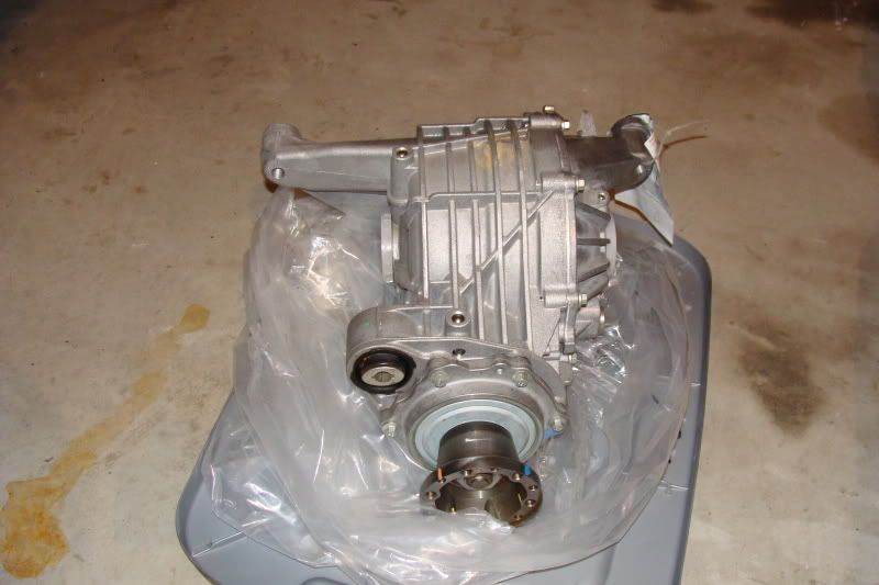
This is a picture of a solution to run with 4l80e tranny. This install stood up for 1086Nm ( 801lb ) on the wheels. I hope i can use this picture as reference Joby otherwise let me know and i will remove it.
Thanks
/Svante.
Thanks
/Svante.
Team Owner
Joined: Aug 2004
Posts: 21,543
Likes: 3,216
From: Park City Utah
That looks like a workable solution. Out at that end of the arm, force is lower b/c you're further from the pivot point; you have "leverage". If the beam is 4' long, that would put that end say, 5' from the pivot point. So your 3500 lbs (in the case of a ZR-1) would now be down to 3500/5=700 lbs of force trying to lift the trans/engine from that adaptor.
Got it. rklessdriver is running stock IRS w/a spool, travel limiters and the stock C-beam....he just POSTED A VIDof his car carrying the front wheels, with a 400+" SBC and slicks so the C-beam can handle a huge amount of force.
Ok, well it should be interesting to see how it will hold up then! The rear suspension is basicly a stock d44, exept for stiffer bushings/shocks. I don�t know how much torque a 355ci will deliver with 20-22psi of boost but my guess would be about 800-850lb to the wheels. I run on semislicks so the traction is a bit better than regular street tires.
/Svante.
/Svante.
Last edited by Tom400CFI; Nov 2, 2014 at 02:39 PM.
Thread Starter
Racer
Joined: Jul 2004
Posts: 315
Likes: 15
From: Ornskoldsvik
That looks like a workable solution. Out at that end of the arm, force is lower b/c you're further from the pivot point; you have "leverage". If the beam is 4' long, that would put that end say, 5' from the pivot point. So your 3500 lbs (in the case of a ZR-1) would now be down to 3500/5=700 lbs of force trying to lift the trans/engine from that adaptor.
Got it. rklessdriver is running stock IRS w/a spool, travel limiters and the stock C-beam....he just POSTED A VIDof his car carrying the front wheels, with a 400+" SBC and slicks so the C-beam can handle a huge amount of force.
Got it. rklessdriver is running stock IRS w/a spool, travel limiters and the stock C-beam....he just POSTED A VIDof his car carrying the front wheels, with a 400+" SBC and slicks so the C-beam can handle a huge amount of force.
Thanks for the inputs.
/Svante
Safety Car

Joined: Apr 2005
Posts: 3,624
Likes: 431
From: Dale City VA
I just want to put it out there that the stock Alum C-Beam deflects way too much in my 84 for me to be happpy with it.
The rear yolk of the driveshaft in my 84 looks like someone took a grinder to it from contact with the C Beam as it deflects and rubs on the driveshaft during launch.
I've only raced using stock parts because that is what the rules allowed when I started.... now that the rules have been loosened to allowing me to build something better - I am.....
Building something out of Chromoly like STEVEN13 has would be a much better idea than modifying the factory C Beam to attach to your Lenco.
Will