


What does the BCM control ?

Thread Starter
Burning Brakes


Joined: Dec 2004
Posts: 1,149
Likes: 143
Does the bcm control the braking etc on the car only ( 6 speed )
I am asking because I have a z06 that had serious issues with the TC / AH system . As a temporary fix I had removed the fuses running the TC / Active handling system until I could get it figured out which never happened. Im so used to the system being deactivated Id like to just remove the whole setup from the car.
- is there any whay to get rid of the "service AH / Sercvice TCS system " on the DIC whith the system removed ??
- Can the BCM be removed or does it effect other components ??
The car brakes flawlessly without the AH / TCS system active, I really dont want to go back now but I hate these messages on the DIC

Tech Contributor


Joined: Dec 1999
Posts: 32,910
Likes: 2,402
From: Anthony TX
CI 6,7,8,9,11 Vet
St. Jude Donor '08
WOW!!  Thats a bit drastic!!!! Lets see if we can get you back in favor with your AH, TC and ABS system!
First off, please read and post all of your DTC codes that are stored in the DIC. Here is a web site for you:
This is the absolute best C5 Code web site!!!
http://www.corvettedoctor.com/Codes_Page.htm
Post the codes and then clear them. See what ones come back after you take it for a drive. Post those. They will be the ones that we concentrate on!
Next! The Body Control Module (BCM) is highly intergrated with all of the other modules! With out the BCM, just about nothing else will work! It is sort of a router. It interperates the signals from the FOB via the Remote Function Actuator, controls the security system, turns on and off all of the interior lights and operates the function lights on the dash plus a ton more stuff!. Without the BCM, the car WILL NOT RUN!
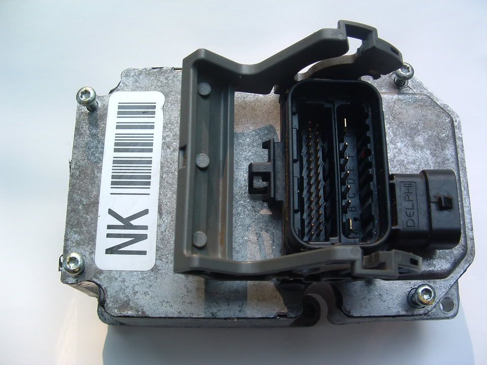
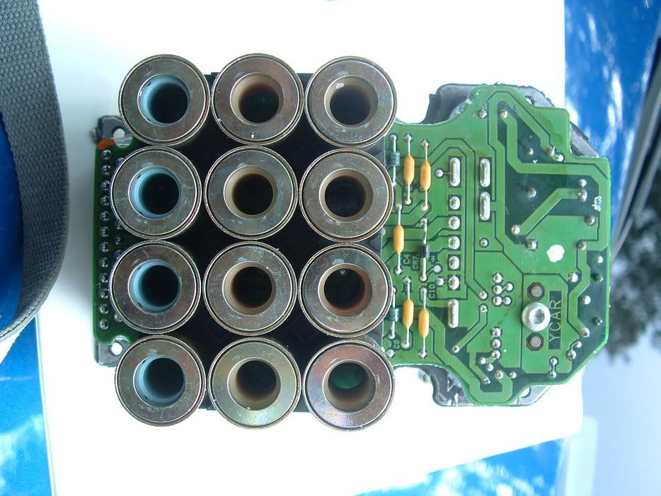
What year Z06 do you have? I have an 02 Z06 and my EBTCM had some SERIOUS issues also! I have had just about every componet of this system apart and back together again. Once you have a properly working EBTCM and AH, TC and ABS works properly, you will be VERY glad that you have it! My problems turned out to be a bad EBTCM:
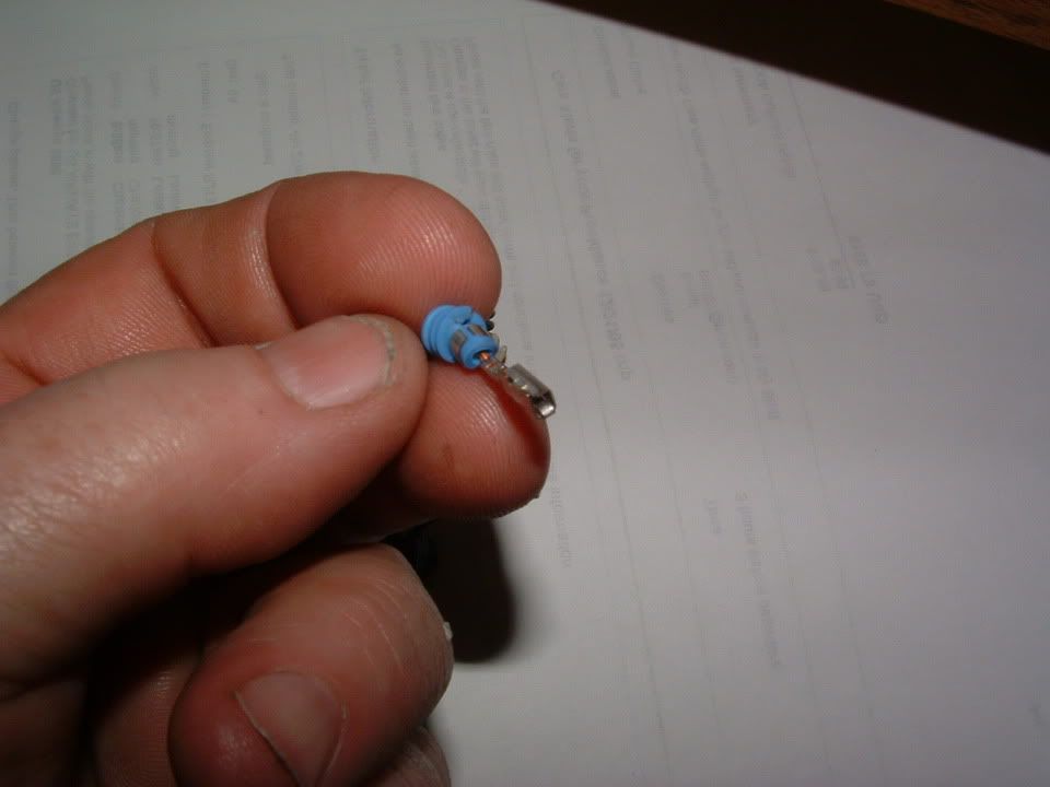
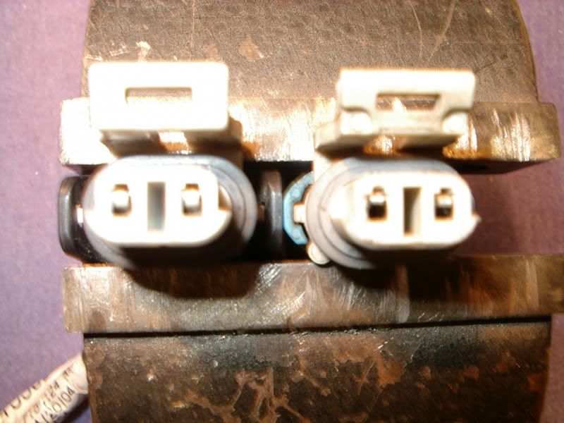
And a bad female pin in the right front wheel speed sensor wiring harness:


My AH, TC and ABS system works PERFECT now!!!
Please provide me the info and codes and with a little bit of troubleshooting, we should be able to get you back on the road!
Bill Curlee
Thats a bit drastic!!!! Lets see if we can get you back in favor with your AH, TC and ABS system!First off, please read and post all of your DTC codes that are stored in the DIC. Here is a web site for you:
This is the absolute best C5 Code web site!!!
http://www.corvettedoctor.com/Codes_Page.htm
Post the codes and then clear them. See what ones come back after you take it for a drive. Post those. They will be the ones that we concentrate on!
Next! The Body Control Module (BCM) is highly intergrated with all of the other modules! With out the BCM, just about nothing else will work! It is sort of a router. It interperates the signals from the FOB via the Remote Function Actuator, controls the security system, turns on and off all of the interior lights and operates the function lights on the dash plus a ton more stuff!. Without the BCM, the car WILL NOT RUN!
What year Z06 do you have? I have an 02 Z06 and my EBTCM had some SERIOUS issues also! I have had just about every componet of this system apart and back together again. Once you have a properly working EBTCM and AH, TC and ABS works properly, you will be VERY glad that you have it!
My problems turned out to be a bad EBTCM:And a bad female pin in the right front wheel speed sensor wiring harness:
My AH, TC and ABS system works PERFECT now!!!
Please provide me the info and codes and with a little bit of troubleshooting, we should be able to get you back on the road!
Bill Curlee
Tech Contributor
Joined: Dec 1999
Posts: 32,910
Likes: 2,402
From: Anthony TX
CI 6,7,8,9,11 Vet
St. Jude Donor '08
One of my buddies is/ was having the same EBTCM problem. Here is what he found was the problem!
Here is a link to his post!
http://forums.corvetteforum.com/show...526&forum_id=1
Here is an example of a bad female pin in a connector.
We are going to get this issue fixed!!!!!
BC
Here is a link to his post!
http://forums.corvetteforum.com/show...526&forum_id=1
Here is an example of a bad female pin in a connector.
We are going to get this issue fixed!!!!!
BC
Last edited by Bill Curlee; Nov 28, 2005 at 08:40 PM.
Thread Starter
Burning Brakes
Joined: Dec 2004
Posts: 1,149
Likes: 143
Thanks for the help I really appreciate it !! 
Im to the point of ripping out the entire GM PCM and going stand alone to rid myself of this system as it will lock up a single front or rear wheel and cause me to lose control.
I just pulled these codes ;
Section 28 TCS
1277 H C ( Torque Signal CKT Malfuncion )
1287 H ( Steering Sensor Rate Malfunction )
1288 H ( no idea )
I had reset the pcm before parking the car for the winter as part of the diagnostics so these DIC's are fresh within the last 2 weeks of driving it.
Race Director


Joined: Apr 2001
Posts: 19,329
Likes: 16
From: Saint Augustine, FL
Mid-TN Events Coordinator
St. Jude Donor '03-'04-'05-'06-'07-'08-'09-'10-'11-'12-'13-'14-'15-'16
I was getting the C1286, C1287 and C1288 on my 99'. All my problems turned out to be the connector that plugs into the steering sensor. I pushed on it, and it 'clicked' into place. It's worth a shot. Just lay down on your back on the drivers side floorboard. Right where the steering column goes into the firewall is where you'll see the sensor, and the connector I speak of.
Not sure about the 1277 code. I believe that code is related with the ability for the TCS system and its ability to communicate with the PCM. I think Bill C. is on track with your solution.
Not sure about the 1277 code. I believe that code is related with the ability for the TCS system and its ability to communicate with the PCM. I think Bill C. is on track with your solution.
Le Mans Master


Joined: Jun 2004
Posts: 6,752
Likes: 3
From: Bethlehem PA
Originally Posted by I brake for nothing
Thanks for the help I really appreciate it !!
Im to the point of ripping out the entire GM PCM and going stand alone to rid myself of this system as it will lock up a single front or rear wheel and cause me to lose control.
I just pulled these codes ;
Section 28 TCS
1277 H C ( Torque Signal CKT Malfuncion )
1287 H ( Steering Sensor Rate Malfunction )
1288 H ( no idea )
I had reset the pcm before parking the car for the winter as part of the diagnostics so these DIC's are fresh within the last 2 weeks of driving it.
I got the same codes and it turned out to be a bad EBTCM module.
The dealer missed the problem, my tuner found it in a heartbeat.
GM told me to stuff my warranty "up me ****"
Sorry to hear your having headaches, seems like a LOT of folks here having trouble with these units.

Scott
Corvette Stories
The Best of Corvette for Corvette Enthusiasts

Top 10 Most Expensive Corvettes Ever Sold on Bring A Trailer
Brett Foote
10 Things Every Corvette Owner Needs (2026 Edition)
Michael S. Palmer
8 Most "Only Corvette Owners Understand" Quirks and Problems
Pouria Savadkouei
10 Reasons the C6 Z06 is Still A Performance Benchmark After 20 Years
Joe Kucinski
How Much Horsepower Every Corvette Engine "LOST" in 1972
Joe Kucinski
Top 10 DOs and DON'Ts for Protecting Your Convertible Top!
Michael S. Palmer
Top 10 Most Explosive Corvettes Ever Made: Power-to-Weight Ratio Ranked!
Joe Kucinski
150 hp to 1,250 hp: Every Corvette Generation Compared by the Specs That Matter
Joe Kucinski
8 Coolest Corvette Pace Cars (and Replicas) of All Time
Verdad Gallardo

Melting Slicks


Joined: Nov 1999
Posts: 2,347
Likes: 857
From: MI
Cruise-In VI Veteran
DTC C1277 Requested Torque Signal Circuit Malfunction

Circuit Description
The PCM monitors various parameters and will not allow Traction Control/Active Handling (if equipped with RPO JL4) operation if any parameter falls beyond a predetermined value.
Conditions for Setting the DTC
A malfunction has been detected by the PCM. The PCM then causes TCS/Active Handling shutdown until the malfunction has been corrected.
Action Taken When the DTC Sets
This is a temporary operational malfunction.
TCS/Active Handling (if equipped with RPO JL4) are disabled.
Indicators that turn on: Car Icon (TCS indicator)
Messages displayed on the DIC: Service Traction System Service Active HNDLG (if equipped with RPO JL4)
Conditions for Clearing the DTC
Condition for DTC is no longer present and scan tool clear DTC function is used.
Fifty ignition cycles have passed with no DTCs detected.
Diagnostic Aids
This code is for information only. It indicates there are no problems in the ABS/TCS/Active Handling system, is used as an aid to the technician.
Test Description
The numbers below refer to step numbers on the diagnostic table.
Checks for proper duty cycle.
Checks for proper frequency.
DTC C1277 Requested Torque Signal Circuit Malfunction Step
Action
Value(s)
Yes
No
1
Was the Diagnostic System Check performed?
--
Go to Step 2
Go to Diagnostic System Check - ABS
2
Check the following grounds, G101 and G108 making sure each ground is clean tight and free of damage. Refer to Ground Ground Distribution Schematics EBTCM/BPMT in Wiring Systems.
Were any loose, damaged, or corroded grounds found?
--
Go to Step 3
Go to Step 4
3
Repair ground as necessary. Refer to Wiring Repairs in Wiring Systems.
Is the repair complete?
--
Go to Diagnostic System Check - ABS
--
4
Turn the ignition switch to the OFF position.
Disconnect the EBTCM connector.
Install J 39700 Universal Pinout Box using the J 39700-25 cable adapter to the EBTCM harness connector and the EBTCM connector.
Turn the ignition switch to the ON position, engine off.
Using J 39200 DMM, measure the DC duty cycle between J 39700 terminals 25 and B.
Is the duty cycle within the range specified in the value(s) column?
85-95 %
Go to Step 5
Go to Step 6
5
Using J 39200 DMM, measure the DC Hz between J 39700 terminals 25 and B.
Is the frequency within the range specified in the value(s) column?
121-134 Hz
Go to Step 13
Go to Step 7
6
Turn the ignition switch to the OFF position.
Disconnect J 39700-25 cable adapter from the EBTCM, leaving J 39700-25 cable adapter connected to the EBTCM harness connector only.
Turn the ignition switch to the ON position, engine off.
Using J 39200 DMM, measure the voltage between terminals 25 and B of J 39700 .
Is the voltage within the range specified in the value(s) column?
4.5-5.5 V
Go to Step 7
Go to Step 8
7
Replace the EBTCM. Refer to Electronic Brake Control Module (EBCM) Replacement .
Is the replacement complete?
--
Go to Diagnostic System Check - ABS
--
8
Turn the ignition switch to the OFF position.
Disconnect the PCM connector C1.
Turn the ignition switch to the ON position engine off.
Using J 39200 DMM, measure the voltage between terminals 25 and B of J 39700
Is the voltage within the range specified in the value(s) column?
Greater than 1 V
Go to Step 9
Go to Step 10
9
Repair CKT 463 for a short to voltage. Refer to Wiring Repairs in Wiring Systems.
Is the repair complete?
--
Go to Diagnostic System Check - ABS
--
10
Turn the ignition switch to the OFF position.
Using J 39200 DMM, measure the resistance between J 39700 terminals 25 and B.
Is the resistance within the range specified in the value(s) column?
OL (infinite)
Go to Step 12
Go to Step 11
11
Repair CKT 463 for a short to ground. Refer to Wiring Repairs in Wiring Systems.
Is the repair complete?
--
Go to Diagnostic System Check - ABS
--
12
Using J 39200 DMM, measure the resistance between terminal 25 of J 39700 and the PCM connector C1 terminal 13.
Is the resistance within the range specified in the value(s) column?
0-2 ohms
Go to Step 13
Go to Step 14
13
Replace the PCM. Refer to PCM/TAC Module Replacement in Engine Controls.
Is the diagnosis complete?
--
Go to Diagnostic System Check - ABS
--
14
Repair CKT 463 for an open. Refer to Wiring Repairs in Wiring Systems.
Is the repair complete?
--
Go to Diagnostic System Check - ABS
--
--------------------------------------------------------------------------------
Melting Slicks
Joined: Nov 1999
Posts: 2,347
Likes: 857
From: MI
Cruise-In VI Veteran
Guide for a 2001 Model year corvette
DTC C1277 or P1571
Circuit Description
The EBCM and the PCM simultaneously control the traction control. The PCM reduces the amount of torque supplied to the drive wheels by retarding spark timing and selectively turning off fuel injectors. The EBCM actively applies the brakes to the front wheels in order to reduce torque.
The EBCM sends a requested torque message via a pulse width modulated (PWM) signal to the PCM. The duty cycle of the signal is used to determine how much engine torque the EBCM is requesting the PCM to deliver. Normal values are between 10 and 90 percent duty cycle. The signal should be at 90 percent when traction control is not active and at lower values during traction control activations. The PCM supplies a pull up voltage of 5 volts that the EBCM switches to ground to create the signal.
The PCM sends a delivered torque message via a pulse width modulated (PWM) signal to the EBCM. The duty cycle of the signal is used to determine how much engine torque the PCM is delivering. Normal values are between 10 and 90 percent duty cycle. The signal should be at low values (around 10 percent) at idle and higher values under driving conditions. The EBCM supplies a pull up voltage of 12 volts that the PCM switches to ground to create the signal.
When certain PCM DTCs are set, the PCM will not be able to perform the torque reduction portion of traction control. A serial data message is sent to the EBCM indicating that traction control is not allowed.
Conditions for Running the DTC
The engine is running.
Conditions for Setting the DTC
C1277
The PCM diagnoses the requested torque signal circuit and sends a serial data message to the EBCM indicating a fault is present.
P1571
One of the following conditions exists:
The PCM detects that requested torque signal is out of the valid range.
The PCM does not receive the requested torque signal.
Action Taken When the DTC Sets
If equipped, the following actions occur:
The EBCM disables the TCS/VSES for the duration of the ignition cycle.
The PCM will store conditions which were present when the DTC set as Fail Records data only.
The Traction Control and Active Handling indicator turns ON.
The DIC displays the following messages:
Service Traction System
Service Active Handling
The ABS remains functional.
Conditions for Clearing the DTC
The condition for the DTC is no longer present (the DTC is not current) and you used the scan tool Clear DTC function.
The condition for the DTC is no longer present (the DTC is not current) and you used the On-Board Diagnostics Clear DTC function.
The EBCM automatically clears the history DTC when a current DTC is not detected in 100 consecutive drive cycles.
The PCM automatically clears the history DTC when a current DTC is not detected in 40 consecutive warm-up cycles.
Diagnostic Aids
The following conditions can cause this concern:
An open in the requested torque circuit
An short to ground or voltage in the requested torque circuit
A wiring problem, terminal corrosion, or poor connection in the requested torque circuit
A communication frequency problem
A communication duty cycle problem
The PCM is not receiving information from the EBCM
Loose or corroded EBCM ground or PCM ground
A DTC P1571 may set along with several other PCM DTCs if the key is held in the CRANK position while the engine is running. The starter lockout function of the PCM is enabled several seconds after the engine is running and prevents the starter from engaging while the engine is running. This will cause a partial loss of power to some components and systems.
Test Description
The numbers below refer to the step numbers on the diagnostic table.
Clear the DTC in order to verify that the fault is present.
Measure the requested torque signal in order to determine if the signal has a valid duty cycle.
Measure the requested torque signal in order to determine if the signal has a valid frequency.
This vehicle is equipped with a PCM which uses an electrically erasable programmable read only memory (EEPROM). When replacing the PCM, the replacement PCM must be programmed.
Step
Action
Values
Yes
No
Schematic Reference: ABS Schematics
Connector End View Reference: ABS Connector End Views or Powertrain Control Module (PCM) Connector End Views in Engine Controls-5.7 L
1
Did you perform the ABS Diagnostic System Check?
--
Go to Step 2
Go to Diagnostic System Check - ABS
2
Inspect the EBCM ground and PCM ground, making sure each ground is clean and torqued to the proper specification. Refer to Circuit Testing and Wiring Repairs in Wiring Systems.
Did you find and correct the condition?
--
Go to Step 13
Go to Step 3
3
Install a scan tool.
Turn ON the ignition, with the engine OFF.
Use the scan tool in order to clear the DTCs in both the EBCM and PCM.
Turn OFF the ignition.
Start the engine.
Does the DTC reset as a current DTC?
--
Go to Step 4
Go to Testing for Intermittent and Poor Connections in Wiring Systems
4
Turn OFF the ignition.
Disconnect the EBCM harness connector.
Install the J 39700 universal breakout box using the J 39700-300 cable adapter to the EBCM harness connector and the EBCM connector.
Start the engine.
Measure the DC duty cycle between the requested torque signal circuit and a good ground.
Is the duty cycle within the specified range?
5-95%
Go to Step 5
Go to Step 6
5
Measure the DC Hz between the requested torque signal circuit and a good ground.
Does the frequency measure within the specified range?
121-134 Hz
Go to Step 8
Go to Step 6
6
Turn OFF the ignition.
Disconnect the J 39700-300 cable adapter from the EBCM connector.
Important
Disconnecting the EBCM connector and turning ON the ignition could cause other modules to set loss of communication DTCs (Uxxxx). Once the EBCM is reconnected, the EBCM may set DTC C1298.
Turn ON the ignition, with the engine OFF.
Measure the voltage from the requested torque signal circuit to a good ground.
Does the voltage measure within the specified range?
4-6 V
Go to Step 10
Go to Step 7
7
Turn OFF the ignition.
Disconnect the powertrain control module (PCM) harness connector.
Test the requested torque signal circuit for the following conditions:
A short to voltage
A short to ground
Refer to Circuit Testing and Wiring Repairs in Wiring Systems.
Did you find and correct the condition?
--
Go to Step 13
Go to Step 10
8
Turn OFF the ignition.
Disconnect the powertrain control module (PCM) harness connector.
Test the requested torque signal circuit for the following conditions:
An open
A high resistance
Refer to Circuit Testing and Wiring Repairs in Wiring Systems.
Did you find and correct the condition?
--
Go to Step 13
Go to Step 9
9
Inspect for poor connections the harness connector of the PCM. Refer to Testing for Intermittent and Poor Connections and Connector Repairs in Wiring Systems.
Did you find and correct the condition?
--
Go to Step 13
Go to Step 11
10
Inspect for poor connections the harness connector of the EBCM. Refer to Testing for Intermittent and Poor Connections and Connector Repairs in Wiring Systems.
Did you find and correct the condition?
--
Go to Step 13
Go to Step 12
11
Important
The replacement PCM must be programmed.
Replace the PCM. Refer to Powertrain Control Module (PCM) Replacement in Engine Controls - 5.7 L.
Did you complete the repair?
--
Go to Step 13
--
12
Replace the EBCM. Refer to Electronic Brake Control Module (EBCM) Replacement .
Did you complete the repair?
--
Go to Step 13
--
13
Use the scan tool in order to clear the DTCs.
Operate the vehicle within the Conditions for Running the DTC as specified in the supporting text.
Does the DTC reset?
--
Go to Step 2
System OK