When you click on links to various merchants on this site and make a purchase, this can result in this site earning a commission. Affiliate programs and affiliations include, but are not limited to, the eBay Partner Network.
Fuse 19 11.98 volts , both sides of the fuse
Fuse 18 11.99 volts , both sides of the fuse
Fuse 17 11.99 volts , both sides of the fuse
Fuse 22 11.98 volts , both sides of the fuse
Fuse 16 11.94 volts , both sides of the fuse
Fuse 13 11.93 volts , both sides of the fuse
Battery voltage with only the hood open was 12.18 volts.
Battery voltage with key in the ignition and in the ON position was 11.99 volts.
This is a new Battery.
Would you agree that my ignition switch is ok ?
Car is a 97 auto with 39K miles.
While repairing the ignition switch, I found this cover or part and not sure where it goes. Can someone tell me where it goes?
That looks like the little rubber insert that goes in the cup holder ... probably fell out when you removed the center console in the process of the repair
I probably missed it but can you tell me....does the ignition switch issue covered here address problems related to the engine not cranking at all, or engine cranking but no-start, or both? Thank you. Mark
Mine would not start ... got a click when tried but no engine rotation ... I was chasing a number of items at the time ... battery would not seem to be charging and intermittent DIC codes that did not seem real ... after I replaced the switch (tried the fix, but was not confident that I got it back together correctly - then bought the new part ... ;-) later I found that the main power cable to the starter was also melted due to header heat and the conductors in the cable had opened ... the remaining working cable was only about half the original size ... that may have been the problem with my starter as well ... but ... it did seem to work better after the switch replacement ... ( I recommend swapping the ignition switch out with new - its inexpensive and just a bunch of screws to replace.)
Then my big fix was ... drum roll ... the two cable connectors that go through the passenger door post were intermittently making contact and would cause the door module to go offline and corrupt the communication from the 7 other control modules (look there cuz my door controls were also intermittent ) ... look for a thread on that ... I just re-sprung the female side of the connectors pins so there was again tension on the male plug when inserted ... and NO more issues for months now ... yea !.
Hi Mark,
when we had the issue, there was nothing - no sound. It was the ignition cylinder. We bought a cylinder online took it to key shop to have it matched to our key. The dealer installed it. Has worked like a champ ever since.
Turns out it was not the ignition switch at all.
Hope this helps.
Jo Rae
Originally Posted by mmg
I probably missed it but can you tell me....does the ignition switch issue covered here address problems related to the engine not cranking at all, or engine cranking but no-start, or both? Thank you. Mark
There are so many single / individual issues that can cause a NO CRANK or a CRANK/NO START that is very difficult to pin it down without doing some investigating/troubleshooting.
Sooooooo many people want someone to say, YEP, that switch is your issue! But yet,, it may NOT be the issue.
If you sit down and analyze C5 START/THEFT DETERRENT/STARTER circuit, you will easily see thing that can easily be checked and tested to narrow down the NO CRANK issue. No crank issues will seldom have related DTCs
Cranks but wont run: Most of the time will be associated with trace DTCs that will point you in a troubleshooting resolve direction
MASSVE NO COMMS reports: When multiple modules report NO COMMS, its usually something causing the serial data buss to not pass digital data. It can be a corrupt signal from say a DOOR MODULE when the power is interrupted due to a bad connection in the power connector in the door connector inside the door pillar/accordion tube. Or a seat control power plug when it hangs down and the power seat crunches the connector and shorts out the wires. Or, the BCM gets WET due to the HVAC Air Box drain clogging up and spilling water into the passengers foot well. BCMs DO NOT like water!!
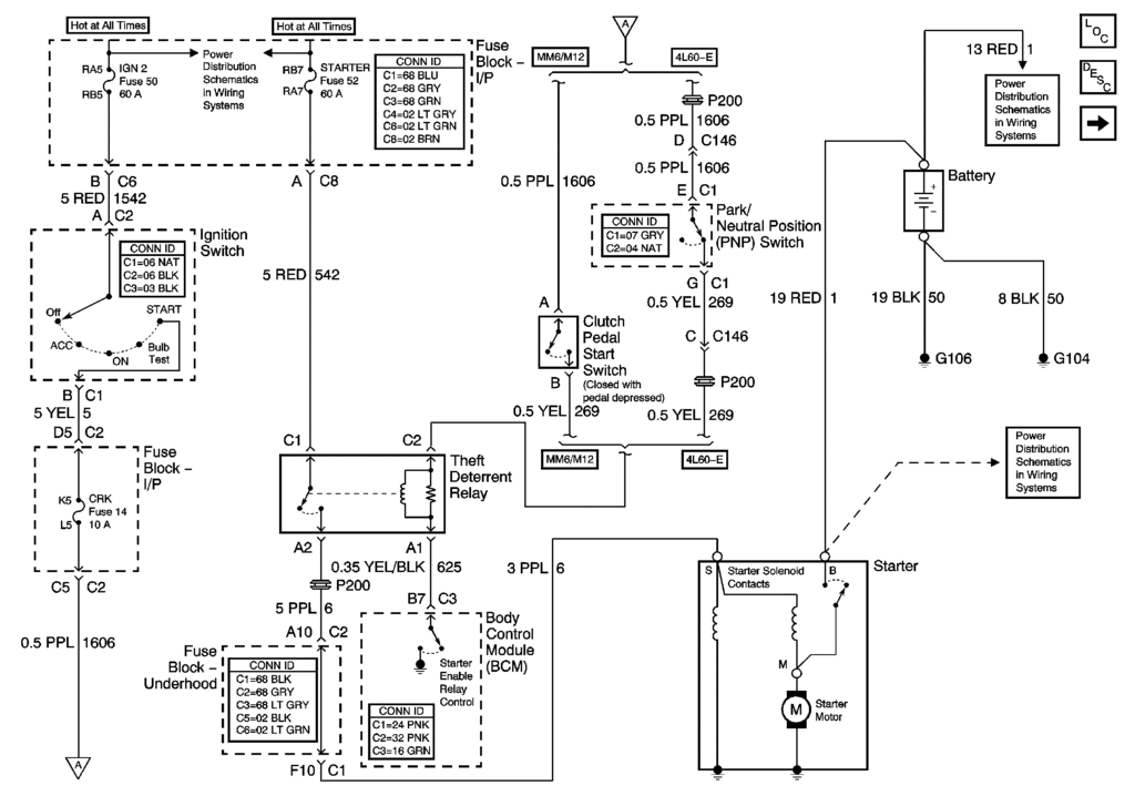
Here is the starter circuit:
If you complete the STARTER INTERLOCK circuit, the Theft Deterrent Relay should ENERGIZE (click) and the starter should turn over. Thats another troubleshooting aid. I have a MN12 trans. If I press in the clutch, turn the ignition key to crank and HOLD it to crank; If I let up on the clutch (break the clutch interlock circuit) and remale it by fully depressing the clutch, the Theft Deterrent Relay should click each time the circuit is made and broken. That tells you that the 12 VDC Low Current side of the relay is functioning along with the security circuit for the BCM..
This can go on forever but the short story is,, DO SOME TROUBLESHOOTING!!!!
Just throwing parts at it gets expensive fast. New battery, ignition switch and starter can add up to quickly. When all the problem really needed was the starter solenoid main power bolt and connection to be cleaned and tightened.
This is my 1st forum post. Just bought my 1st vette and picked it up last weekend, drove it 3 hrs 240 miles from my house issue free. I get home and give my son a ride in it and open up the throttle,felt awesome. After a while my gauges read reduced power, low tire pressure, check abs traction controlfuel went to 0, temp to 250, oil to 0, but car ran perfect still. Got it home and looked up issues and found about the AC drain and looking for moisture, sure enough there was. TDR relay was pretty wet, took the bcm off and was dry. Bought a new tdr relay, checked all the fuses, deleted codes SDM U1040 PCM P1689 BCM B0432. Dash clear and everything is working normally.
Tried to start it and starter doesnt engage. Security light is off with key in the on position. I checked voltage on TDR relay, red has power, when I turn key to start purple wire does not get voltage. The 2 smaller yellow wires get 12v. With key on I can start the car by bypassing the red wire and purple on the TDR. car drives fine, no issues.
I took apart the grounds and cleaned them up very good. Its almost 1am and im about to go take the switch apart since I have an appointment to take my car to the dealership at 8am. Anything else I should look for? Battery is new and checked, clean grounds, dried up pass side area, new tdr.
thanks for the help!!
This is my 1st forum post. Just bought my 1st vette and picked it up last weekend, drove it 3 hrs 240 miles from my house issue free. I get home and give my son a ride in it and open up the throttle,felt awesome. After a while my gauges read reduced power, low tire pressure, check abs traction controlfuel went to 0, temp to 250, oil to 0, but car ran perfect still. Got it home and looked up issues and found about the AC drain and looking for moisture, sure enough there was. TDR relay was pretty wet, took the bcm off and was dry. Bought a new tdr relay, checked all the fuses, deleted codes SDM U1040 PCM P1689 BCM B0432. Dash clear and everything is working normally.
Tried to start it and starter doesnt engage. Security light is off with key in the on position. I checked voltage on TDR relay, red has power, when I turn key to start purple wire does not get voltage. The 2 smaller yellow wires get 12v. With key on I can start the car by bypassing the red wire and purple on the TDR. car drives fine, no issues.
I took apart the grounds and cleaned them up very good. Its almost 1am and im about to go take the switch apart since I have an appointment to take my car to the dealership at 8am. Anything else I should look for? Battery is new and checked, clean grounds, dried up pass side area, new tdr.
thanks for the help!!
If the TDR was wet,,, The BCM was almost certainly wet at sometime. The BCM actually grounds the TDR (yellow/black stripe wire) which allows the relay to energize the coil in the relay which closes the main contacts to apply power to the solenoid.
If you read 12 VDC on the yellow wire, the BCM wasn’t grounding the yellow black wire. That is what you have to figure out. You can actually ground that yellow black wire and the TDR will operate and the engine will crank and it will crank and run if you have the ignition key ON.
Be careful and make sure the car is out of gear/ in park and secure if you screw with that relay..
The BCM will not ground that relay if ALL the security features are not met and or the BCM is damaged or that circuit is damaged.
On my ZO6, if I have a corrupted SERIAL DATA BUSS,, it will do the same thing. Won’t crank. Do you have any NO COMMS DTCs
If you have wacky gages and the car still ran,, you had a corrupted serial data buss. When it spazzes out, and or wont crank,, see if you have NO COMMS DTCs
Bill
Last edited by Bill Curlee; Mar 28, 2015 at 11:50 AM.
I just checked codes and got a few
10-PCM/ P1626
AB-SCM/ U1255H
60-IDC / U1016h, U1064h, U1040h, U1176h, U1088h, U1160h
80-radio/U1064H, U1016h, U1096H
A1-LDCM/U1064H
A0-LDCM/U1064H
connected the Tech2 and checked cranking. Showed"run" but didn't show cranking when trying to start the car. No security light on.
I just checked codes and got a few
10-PCM/ P1626
AB-SCM/ U1255H
60-IDC / U1016h, U1064h, U1040h, U1176h, U1088h, U1160h
80-radio/U1064H, U1016h, U1096H
A1-LDCM/U1064H
A0-LDCM/U1064H
connected the Tech2 and checked cranking. Showed"run" but didn't show cranking when trying to start the car. No security light on.
This is why it wont runTC P1626 Theft Deterrent Fuel Enable Signal Lost
Heres what the U series codes mean:
DTC U1000 and DTC U1255 Class 2 Communication Malfunction
DTC U1001-U1254 Lost Communication with XXX
DTC U1255 Serial Data Line Malfunction
DTC U1300 Class 2 Short to Ground
DTC U1301 Class 2 Short to Battery
Circuit Description for P 1626
The system is designed to disable vehicle operation if the incorrect key or starting procedure is used. The theft deterrent module enables the crank circuit to the starter and sends a signal to the PCM if the correct key is being used. If the proper signal does not reach the PCM on the fuel enable circuit, the PCM will not pulse the injectors ON and thus not allow the vehicle to continue to operate, even if the crank circuit is bypassed. The proper signal is between 40-60 Hz and is measured using the DC scale on the DVM.
Conditions for Setting the DTC
•The Engine is running or cranking.
•The PCM does not receive the correct signal from the Theft Deterrent Module.
•Condition present for 1.7 seconds.
Action Taken When the DTC Sets
•DTC P1626 will be stored in the PCM memory when the diagnostic runs and fails.
•The Malfunction Indicator Lamp (MIL) will not illuminate.
•The PCM will record operating conditions at the time the diagnostic fails. This information will be stored in Failure Records.
•Engine will start and then stall or engine will not crank.
Conditions for Clearing the MIL/DTC
•A history DTC will clear after 40 consecutive warm-up cycles, if no failures are reported by this or any other non-emission related diagnostic.
•A last test failed (Current DTC) will clear when the diagnostic runs and does not fail.
•PCM battery voltage is interrupted.
•Using a scan tool.
Diagnostic Aids
•If the engine starts and then stalls, indicates that the portion of the theft deterrent module, which generates the signal to the PCM is not operating or circuit 229 is open or shorted to ground. If the theft deterrent module is found to be OK, as determined from service category Electrical or Control Module Circuits, the PCM may be at fault, but this is not a likely condition.
•Using Freeze Frame and/or Failure Records data may aid in locating an intermittent condition. If the DTC cannot be duplicated, the information included in the Freeze Frame and/or Failure Records data can be useful in determining how many miles since the DTC set. The Fail Counter and Pass Counter can also be used to determine how many ignition cycles the diagnostic reported a pass and/or a fail. Operate vehicle within the same freeze frame conditions (RPM, load, vehicle speed, temperature etc.) that were noted. This will isolate when the DTC failed.
•Refer to Symptoms .
Test Description
Number(s) below refer to step numbers on the diagnostic table.
2.
If DTC P1626 is stored, and the engine will not crank, indicates that there is a theft deterrent system problem or an incorrect key or starting procedure is being used. For any test that requires probing the PCM or a component harness connector, must use the Connector Test Adapter Kit J 35616-A. Using this kit will prevent damage to the harness connector terminals.
3.
If the engine does not crank indicates there is a problem with the theft deterrent module.
4.
This determines if the theft deterrent module is capable of sending a signal to the PCM.
Step
Action
Value(s)
Yes
No
1
Was the Powertrain On-Board Diagnostic (OBD) System Check performed?
--
Go to Step 2
Go to Powertrain On Board Diagnostic (OBD) System Check
2
Crank the engine.
Does the engine start and run?
--
Go to Powertrain On Board Diagnostic (OBD) System Check
Go to Step 3
3
Does the engine crank?
--
Go to Step 4
Go to Service Category Theft Deterrent Systems
4
•Turn the Ignition OFF.
•Disconnect the PCM connector C1.
•Connect a fused jumper wire between the PCM harness connector terminal C1-25 and a 5.0 volt source (IAT sensor harness connector terminal B will work).
•Using the DVM J 39200, select the DC volts and Hertz (Hz) scale.
•Turn the Ignition ON.
•Using the DVM connected to ground, probe the PCM harness connector terminal C1-25.
Is the hertz within the range specified in the values column?
40-60Hz
Go to Step 7
Go to Step 5
5
Check circuit 229 for the following:
•An open.
•A short to ground.
•A short to B+.
Was a condition found and corrected?
--
Go to Step 9
Go to Step 6
6
Replace the Theft Deterrent Module, Refer to Service Category Theft Deterrent Systems .
Is the repair completed?
--
Go to Step 9
--
7
Inspect the PCM connector C1-25 for good terminal tension.
Did the terminal require a repair?
--
Go to Step 9
Go to Step 8
8
Important
Replacement PCM must be programmed. Refer to PCM Replacement/Programming .
Replace the PCM.
Is the action complete?
--
Go to Step 9
--
9
•Using the scan tool, select DTC, Clear Info.
•Start engine and idle at normal operating temperature.
•Select DTC, Specific, then enter the DTC number which was set.
•Operate vehicle within the conditions for setting this DTC as specified in the supporting text, if applicable.
Does the scan tool indicate that this test ran and passed?
--
Go to Step 10
Go to Step 2
10
Using the scan tool, select Capture Info, Review Info.
Are any DTCs displayed that have not been diagnosed?
Are you sure that the securit light is out when the ignition is ON and you have a good key with a good resistor pellet and the sensor is properly reading the pellet?
Are you sure that the securit light is out when the ignition is ON and you have a good key with a good resistor pellet and the sensor is properly reading the pellet?
Try your second key and or clean the pellet.
Bill
Try your second key and or clean the pellet.
Bill[/QUOTE]
I cleaned the pellet, tried both keys. The security light does turn off
with both keys in ON position. Both keys ohmd @1.86. Cleared codes and tried cranking, checked codes again and none.
I purchased a newACDElCO ignition switch(electrical part) from the dealer. Going to see the condition of the one currently on the car. Ill check the connections in the door jambs and anything else you have mentioned on this issue on other threads.
I took this weekend off to take care of this since I have to work 7am til 830pm during the week Your help is very appreciated!
Last edited by 210fused; Mar 28, 2015 at 08:19 PM.
Thanks for all input. Turns out it appears my car was just somewhat battery drained. I fully charged the battery and all is well now with starting. We'll see if it continues! Mark
Well, checked all the fuses:
Under hood- 19,18,17,22,16,13
Inside pass floorboard-21,22,19 22 did not have a fuse and was blank on the diagram. I checked all the BCM fuses and were good.
Took my switch apart and had some buildup so cleaned it up with 400 then 1000grit. Tried brand new switch also with no luck. When I turn the key forward fuelpump kicks on for a few secs.
Took the connectors apart between the door jam and looked good.
Thinking maybe the BCM, not sure what else to check besides safety neutral switch (automatic transmission)
Update: Checked all the drains Bill had posted about and ac drain was filthy. I went ahead and took out the blower fan to see how it looked. Put it back together, reinstalled the BCM, put back the TDR relay and connected the battery. Car started up! The only thing now is my blower fan isnt blowing, gonna check if its not in a bind when I put it back in.
I did notice a black 3 wire connector right above the BCM that had a black, orange and yellow wire but was not terminated to anything, just had black tape similar to what all the other wires are held with, like a black duct tape.
Last edited by 210fused; Mar 29, 2015 at 05:27 PM.
Well, checked all the fuses:
Under hood- 19,18,17,22,16,13
Inside pass floorboard-21,22,19 22 did not have a fuse and was blank on the diagram. I checked all the BCM fuses and were good.
Took my switch apart and had some buildup so cleaned it up with 400 then 1000grit. Tried brand new switch also with no luck. When I turn the key forward fuelpump kicks on for a few secs.
Took the connectors apart between the door jam and looked good.
Thinking maybe the BCM, not sure what else to check besides safety neutral switch (automatic transmission)
Update: Checked all the drains Bill had posted about and ac drain was filthy. I went ahead and took out the blower fan to see how it looked. Put it back together, reinstalled the BCM, put back the TDR relay and connected the battery. Car started up! The only thing now is my blower fan isnt blowing, gonna check if its not in a bind when I put it back in.
I did notice a black 3 wire connector right above the BCM that had a black, orange and yellow wire but was not terminated to anything, just had black tape similar to what all the other wires are held with, like a black duct tape.
Those three wires are your AUX power wires. One is HOT, one is ignition switched HOT and one is ground.. It the SAFE way to connect things to your electrical system. The power wires are 20 amp fused circuits.
Last edited by Bill Curlee; Jun 16, 2015 at 08:53 PM.
I've been having intermittent (and getting worse/more frequent) charging system / low voltage warnings in the DIC. After some searching I found this thread and pulled my ignition switch. Sure enough, same problem, same bad contacts. Thanks Bill, and everyone else in this thread!
My switch keeps getting corrosion after a few weeks and it's starting to be a pain to take apart and clean all the time. My thought is to put in a push button start system that I will have two switches to get the "on" and "acc" power and then the push button will handle the "crank". From Bill's original sketch it looks like I would power the first switch for "on" which would power H & F. Then power the second switch for "acc" which would connect ED. And finally hit the push button which would connect C. Release the button and the switches stay on and the vehicle would run. Depower the switches and the vehicle will shut off.
Does this seem correct?
I understand that the car can be started without a key. The doors can still be locked and someone would have to find the switches and know the correct sequence for power which if they can figure that out, they would be able to cut wires and do it anyways.
There absolutly NO reason why your OEM ignition switch shouldn't work.
Have you tried a NEW OEM switch???
You still may have something wrong and it may NOT be inside the switch.
Look very closely at the two harness side CONNECTORS that plug into the switch.
If ANY of the "FEMALE" pins in either of those connectors are spread apart, it will cause issues.
The only "FOR SURE" method of making proof positive that the female pins are properly making positive contact with the male pins in the switch is to do a "PIN PULL TEST"
Get a spare male pin (the same thickness as male pin in the switch) and insert and extract the male pin in the female pin inside the harness connector. IF you don't have friction resistance when the pin is inserted and or extracted, that female pin is BAD!
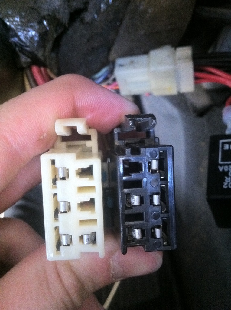
This harness connector has a bunch of badly spread pins and caused a bunch of issues!!!





















 TC P1626 Theft Deterrent Fuel Enable Signal Lost
  Your help is very appreciated!