


Voltage Experts...

Le Mans Master


Joined: Sep 2000
Posts: 6,976
Likes: 527
From: Clouds Over California
OK here is my issue and I think there is enough info on this thread to answer and help both the OP and me.
I was driving along and my vdc dropped and the warning appeared on the dic.
Battery was fully charged as I just took the tender off.
I took out the meter and measured the alt field wire (biggest redwire connecting the post on the alternator). It was only reading 12.2vdc when the car was running....it should be running 14.4. I took the Alt into a shop they replaced the regulator and had it tested...all good 14.8vdc on the test bench. Put it back on the car and ......same problem.
I read out the 12vdc (sense) constant (large red) on the alt connector (comes from the starter) and it read 12vdc constant (same as battery actually 12.2vdc). Then I went to read out the small red wire this is 12vdc swithced (ignition) and it reads 10.6 vdc with the ignition switched on.....where does the small red wire come from.....the PCM?
As a test I ran an independent wire (jumpered) over from a 12vdc switched source (fan fuse at the underhood fuse box) over to to the alt connector and hooked it up to the 12vdc switched (ign wire). Started the car and everything worked......back of alt post wire (pos) to starter read 14.4 vdc...the dic read 13.9vdc.
Is there a fuse to the small red wire...where does it get it source from? It doesn't come from the starter or does it? I think only the large red wire at the alt connector 12vdc constant (sense) is the only red wire from the connector that pics up from the starter...and of course the very large red wire that goes from the starter to the post on the alt.
I also read out the starter post and it reads 12vdc. It appears that the alt is not getting enough (ignition vdc) to exite the alt into charging. I could just run one wire to the alt from a 12vdc switched source and it will work...but I want to troubleshoot the issue.
Can the PCM be a problem...assuming the small red wire (12vdc) switched only comes from the PCM???? Or is there a fuse?
Thanks

Tech Contributor


Joined: Dec 1999
Posts: 32,910
Likes: 2,402
From: Anthony TX
CI 6,7,8,9,11 Vet
St. Jude Donor '08
OK here is my issue and I think there is enough info on this thread to answer and help both the OP and me.
I was driving along and my vdc dropped and the warning appeared on the dic.
Battery was fully charged as I just took the tender off.
I took out the meter and measured the alt field wire (biggest redwire connecting the post on the alternator). It was only reading 12.2vdc when the car was running....it should be running 14.4. I took the Alt into a shop they replaced the regulator and had it tested...all good 14.8vdc on the test bench. Put it back on the car and ......same problem.
I read out the 12vdc (sense) constant (large red) on the alt connector (comes from the starter) and it read 12vdc constant (same as battery actually 12.2vdc). Then I went to read out the small red wire this is 12vdc swithced (ignition) and it reads 10.6 vdc with the ignition switched on.....where does the small red wire come from.....the PCM?
As a test I ran an independent wire (jumpered) over from a 12vdc switched source (fan fuse at the underhood fuse box) over to to the alt connector and hooked it up to the 12vdc switched (ign wire). Started the car and everything worked......back of alt post wire (pos) to starter read 14.4 vdc...the dic read 13.9vdc.
Is there a fuse to the small red wire...where does it get it source from? It doesn't come from the starter or does it? I think only the large red wire at the alt connector 12vdc constant (sense) is the only red wire from the connector that pics up from the starter...and of course the very large red wire that goes from the starter to the post on the alt.
I also read out the starter post and it reads 12vdc. It appears that the alt is not getting enough (ignition vdc) to exite the alt into charging. I could just run one wire to the alt from a 12vdc switched source and it will work...but I want to troubleshoot the issue.
Can the PCM be a problem...assuming the small red wire (12vdc) switched only comes from the PCM???? Or is there a fuse?
Thanks
You need to measure the voltages at the fuses that get feed from both sources and see if your getting the correct voltages from both sources. If one is not the full "BATTERY VOLTAGE",,,theres your issue.
Bill
Le Mans Master
Joined: Sep 2000
Posts: 6,976
Likes: 527
From: Clouds Over California
There are TWO voltages that feed the PCM and any module for that matter: HOT ALL TIMES & Hot in Start or Run.. There BOTH 12 VDC and come from the battery but one Hot in Start or Run goes through the IGNITION SWITCH.
You need to measure the voltages at the fuses that get feed from both sources and see if your getting the correct voltages from both sources. If one is not the full "BATTERY VOLTAGE",,,theres your issue.
Bill
You need to measure the voltages at the fuses that get feed from both sources and see if your getting the correct voltages from both sources. If one is not the full "BATTERY VOLTAGE",,,theres your issue.
Bill
I am assuming you mean the fuses (mini) in the under the hood fuse panel. I used a meter on these and when the ignition is turned on I read 12.2vdc on the meter...when I put the leads on the little metal tips on top of the fuses.....were there specific fuses that you had in mind?
I get the hot all the time vdc of 12vdc. I traced the battery wire down to the starter and followed you recommendation to check the fuseable links and for corrosion on the starter solenoid wires. I disconnected the 3 wires on the starter terminal and clean them...however when I went to put the wires back on the post...the post on the starter solenoid had a little play in it...I could actually push is in and out a little bit...but when I put back on the terminal (3 wires...orange, grey, and red) it tighted right back up with no play...I can't remember it doing that before.
What's next Bill?

Last edited by Shinobi'sZ; Aug 21, 2008 at 01:04 AM.
Thread Starter
Le Mans Master


Joined: May 2006
Posts: 6,774
Likes: 363
From: Midland TX
My Post #70 lists the multimeter readings I got in motion and at stop.
Sorry for the slow response, the Forum Recent Topics is not updating correctly.
Le Mans Master
Joined: Sep 2000
Posts: 6,976
Likes: 527
From: Clouds Over California
Anyway somebody told me that how you tell a fuseable link is bad is by how they actually feel...if they are really spongy then the wire is burned up.....my grey (on the solinoid) wire has no regidity whatsoever and is very spongy. Can anybody confirm this?????
I guess I will try and take a voltage or resistance reading from the terminal to other end of the link...or should I do a resistance check?
Then I got to find a fuseable like to replace it with...if it's bad.
Thread Starter
Le Mans Master
Joined: May 2006
Posts: 6,774
Likes: 363
From: Midland TX
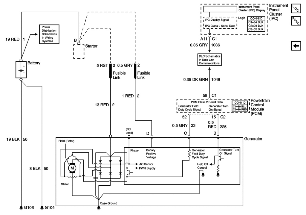
I have no experience with fusible links, but if I am not mistaken, is not the GREY fusible link the main power feed from the alternator to the battery via the starter terminal? I was thinking the Rust-colored fusible link wire was the sense wire (looking at BC's diagram)?

Pro

Joined: Sep 2007
Posts: 735
Likes: 7
From: Bucks County Pa
I have no experience with fusible links, but if I am not mistaken, is not the GREY fusible link the main power feed from the alternator to the battery via the starter terminal? I was thinking the Rust-colored fusible link wire was the sense wire (looking at BC's diagram)?
The Red fusible link to gray wire going to the starter says Battery Positive Voltage on the schematic. And it is connected inside the box in the schematic which is the regulator, so it is the sense wire. The Red fusible link to rust wire going to the starter is connected by an eyelet,(if you look at the schematic and see that the rust to red wire has a small circle at the end where it connects to the alt, that is an eyelet connection), to the field of the alt, so it is the charging wire. Then you have the red wire ,(turn on signal ), connected inside the regulator rectangle, which of course tells the alt to wake up, and the gray field duty cycle signal wire connected inside the reg, which sends the signal back to the ipc, by way of the pcm. My experience with fusible links from many years ago is that they have a degree of stiffness to them. You can measure the resistance and continuity from end to end, or even from the end of the fusible part to the other end of the fusible part.
Good Luck
EDIT- Choreo, I just re read your #70 post, and the output as recorded on your mm seems close to normal, the voltage usually drops when slowing down, and if you had the lights on and they dimmed, this would indicate a weak battery, as could the voltage drop. I think the issue is with your signal to the ipc, possibly the ground on the door post.
Last edited by bestvettever; Aug 21, 2008 at 11:25 PM.
Corvette Stories
The Best of Corvette for Corvette Enthusiasts

Top 10 Most Expensive Corvettes Ever Sold on Bring A Trailer
Brett Foote
10 Things Every Corvette Owner Needs (2026 Edition)
Michael S. Palmer
8 Most "Only Corvette Owners Understand" Quirks and Problems
Pouria Savadkouei
10 Reasons the C6 Z06 is Still A Performance Benchmark After 20 Years
Joe Kucinski
How Much Horsepower Every Corvette Engine "LOST" in 1972
Joe Kucinski
Top 10 DOs and DON'Ts for Protecting Your Convertible Top!
Michael S. Palmer
Top 10 Most Explosive Corvettes Ever Made: Power-to-Weight Ratio Ranked!
Joe Kucinski
150 hp to 1,250 hp: Every Corvette Generation Compared by the Specs That Matter
Joe Kucinski
8 Coolest Corvette Pace Cars (and Replicas) of All Time
Verdad Gallardo
Thread Starter
Le Mans Master
Joined: May 2006
Posts: 6,774
Likes: 363
From: Midland TX
The Red fusible link to gray wire going to the starter says Battery Positive Voltage on the schematic. And it is connected inside the box in the schematic which is the regulator, so it is the sense wire. The Red fusible link to rust wire going to the starter is connected by an eyelet,(if you look at the schematic and see that the rust to red wire has a small circle at the end where it connects to the alt, that is an eyelet connection), to the field of the alt, so it is the charging wire. Then you have the red wire ,(turn on signal ), connected inside the regulator rectangle, which of course tells the alt to wake up, and the gray field duty cycle signal wire connected inside the reg, which sends the signal back to the ipc, by way of the pcm.
This is a bit off the subject, but not being an electrician what do the "numbers" in the schematic refer to - like "13 RED | 2" and "1 RED | 2"? I get the "color" obviously, but do these numbers refer to - the gauge of wire, circuit number, or what?
Pro
Joined: Sep 2007
Posts: 735
Likes: 7
From: Bucks County Pa
This makes sense to now.
This is a bit off the subject, but not being an electrician what do the "numbers" in the schematic refer to - like "13 RED | 2" and "1 RED | 2"? I get the "color" obviously, but do these numbers refer to - the gauge of wire, circuit number, or what?
This is a bit off the subject, but not being an electrician what do the "numbers" in the schematic refer to - like "13 RED | 2" and "1 RED | 2"? I get the "color" obviously, but do these numbers refer to - the gauge of wire, circuit number, or what?
++++++++++++++++++++++++++++++++++
Wire Size for Runs up to 15 Feet
Gauge Metric Amps
8, 8.0, 32-40
10, 5.0, 28-35
12, 3.0, 18-30
14, 2.0, 12-20
16, 1.0, 8-13
18, 0.8, 6-10
20, 0.5, 4-6
22, 0.22, 2-3
(capacity depends on wire quality & length of run)
++++++++++++++++++++++++++++++++++
The number after the color has to do with it's placement in the overall system pertaining to the design and schematic clarity. Like a big outline. Then there are the circuit numbers themselves that have to correspond to all connections on that circuit.The numbers that have a letter before them usually denote some form of connector, or device.
And then there are the symbols like the small circle at the end of a wire that denotes an eyelet.
Hope this clears up some of it.
Good luck
Last edited by bestvettever; Aug 22, 2008 at 04:43 PM.
Le Mans Master
Joined: Sep 2000
Posts: 6,976
Likes: 527
From: Clouds Over California
Ok my s#!t is fixed!
My old alternator that I had rebuilt is no good. I borrowed a friends spare alternator (AVB) yesterday and put it on this morning and all works perfect 13-14vdc on the dic while driving with ac, radio, and both fans running.
Here is what I observed (similiar to my 2000 camaro alt).
The small red wire that comes from the pcm which is the "turn on voltage" does not necessarilly take 12vdc switched to excite the alt. When it is hooked up it reads 5 vdc just like my single wire connector on the camaro.
The turn on voltage to the alt (small red wire from the PCM) is not 12vdc...at least not while it is hooked up to the alt with the car running.
Looks like I will be taking this back up with the shop that rebuilt my original alternator.
Here were the read outs.
Not running
Battery (+) terminal 14vdc (full charged)
Alternator (+) on the post 14vdc (no drop)
Running
The battery and alt were the almost the same. Alt read 14.4 vdc and battery read 13.9-14.1 depending on the fans kicking on and off.
the dic was showing 13.8-14.0 vdc...so about a .2 to .4 vdc drop between the dic and actual.
the only time it dropped to 13.0 vdc was while driving with radio, ac max, and both rad fans on....however with all this stuff on it did kick down to 12.8 vdc real quick on the dic when I got into boost and the BAP kicked in...but it immediatly went back up when I got out of boost.
When I parked and was idling...ac off. it was back up to 13.8-13.9vdc on the dic and around 14.0-14.1 on the alt post.
Choreo if you are still having problem you may just want to recheck any parts you replaced an not assume they are good because you purchased them new.
Last edited by Shinobi'sZ; Aug 23, 2008 at 05:21 PM.
Thread Starter
Le Mans Master
Joined: May 2006
Posts: 6,774
Likes: 363
From: Midland TX
Le Mans Master
Joined: Sep 2000
Posts: 6,976
Likes: 527
From: Clouds Over California
Good luck finding out whats drawing down on your voltage...do you have an aftermarket stereo?
Thread Starter
Le Mans Master
Joined: May 2006
Posts: 6,774
Likes: 363
From: Midland TX
Here are tonight's readings taken at the red dots indicated to G-101 or G-102. The fact that ALL locations show exactly the same voltage when car is turned off leads me to believe that all the wiring and connections are OK?
The 14.18v output at the alternator (at idle when first starting up) looks good to me, but two things still have me stumped.
(1) Why do the gauges always show low?
(2) Why do they keep dipping when coming to stop (then recover) - everything always looks consistent above about 1000 RPM ALWAYS?
(Note: I could not figure out how to take readings at alternator locations B & C with car running)
Reminder: I have replaced Battery, Alternator and Ignition Switch - ALL with NEW (not remanufactured) parts - this behavior remains unaffected.
Last edited by Choreo; Aug 26, 2008 at 02:32 AM.
Pro
Joined: Sep 2007
Posts: 735
Likes: 7
From: Bucks County Pa
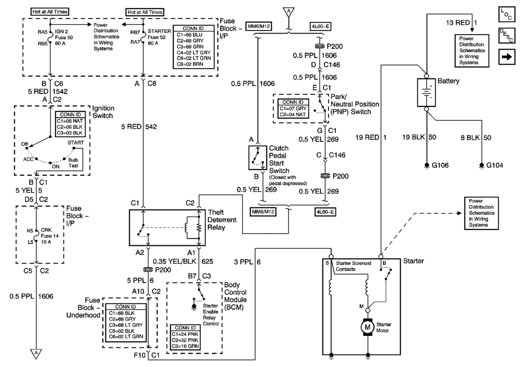
Hi, Here's a thought. The volt gauge and dic get their info from the IGN 1 reading at fuse 19 ip fuse block which is Hot In Start and On only. The other guages in the cluster get a class 2 signal from the PCM, but the Volt guage gets it direct from the batt voltage, by way of the ign 1 circuit. The IPC is grounded at G104- Next to battery box . If you get the same readings comparing the batt to the readings up to and at the ipc, that pretty much confirms that the IPC is the problem. SEE BELOW
Voltmeter
The IPC displays the system voltage as detected at the ignition 1 input of the IPC. The voltage on the volt gage is also displayed on the DIC. The IPC displays high or low voltage on the DIC when the IPC detects voltage levels out of range.
Perhaps you might find it illuminating to test the volt output at that source. And check the ground and splice packs to the ground. Also the connector pins for tightness dealing with the circuit.
As Always Good Luck
Schematic Below
++++++++++++++++++++++++++++++++++
Last edited by bestvettever; Aug 26, 2008 at 01:01 PM.
Thread Starter
Le Mans Master
Joined: May 2006
Posts: 6,774
Likes: 363
From: Midland TX
Guess I have beaten this topic to death. I am out of ideas as to what could be causing BOTH of the issues I am having, but they definitely are tied together. I am beginning to think it is computer related since almost every time I turn the car off and then start it back up, it chooses a new voltage range to swing in during that session. Today my first run was the best I have had since the problem started - DIC showed 13.7v for about 15 minutes (which is probably about 14.2v actual) and the dips when coming to a stop were 13.1v. Then after I parked the car at a restaurant and started back up it could not get past 12.6 at the highest reading for that session. I then stopped the car and as soon as I started the car got all the EBCM warnings on the DIC (done this 4 times now in the past month). I turned the car off, then started it back up and the warnings all disappeared?
BTW - the "Generator Field Duty Cycle Signal" (the .5 Grey wire between the Alt and the PCM) - Is this strictly to feed voltage info to the IPC via the PCM or does the PCM use this info to somehow control the voltage level in the car? If it is just for the dash gauges, why does it have to go through the PCM?
BTW - the "Generator Field Duty Cycle Signal" (the .5 Grey wire between the Alt and the PCM) - Is this strictly to feed voltage info to the IPC via the PCM or does the PCM use this info to somehow control the voltage level in the car? If it is just for the dash gauges, why does it have to go through the PCM?
Pro
Joined: Sep 2007
Posts: 735
Likes: 7
From: Bucks County Pa
Guess I have beaten this topic to death. I am out of ideas as to what could be causing BOTH of the issues I am having, but they definitely are tied together. I am beginning to think it is computer related since almost every time I turn the car off and then start it back up, it chooses a new voltage range to swing in during that session. Today my first run was the best I have had since the problem started - DIC showed 13.7v for about 15 minutes (which is probably about 14.2v actual) and the dips when coming to a stop were 13.1v. Then after I parked the car at a restaurant and started back up it could not get past 12.6 at the highest reading for that session. I then stopped the car and as soon as I started the car got all the EBCM warnings on the DIC (done this 4 times now in the past month). I turned the car off, then started it back up and the warnings all disappeared?
BTW - the "Generator Field Duty Cycle Signal" (the .5 Grey wire between the Alt and the PCM) - Is this strictly to feed voltage info to the IPC via the PCM or does the PCM use this info to somehow control the voltage level in the car? If it is just for the dash gauges, why does it have to go through the PCM?
BTW - the "Generator Field Duty Cycle Signal" (the .5 Grey wire between the Alt and the PCM) - Is this strictly to feed voltage info to the IPC via the PCM or does the PCM use this info to somehow control the voltage level in the car? If it is just for the dash gauges, why does it have to go through the PCM?
The only thing that determines the alt output is the reg, once it's turned on.
I really think you are down to 2 possibilities, do the above test to confirm whether the ipc is not reading correct, if it is, the reg is bad no matter if it's the 2nd one or the 10th one. this assumes that you've checked all the wiring and grounds correctly.
Good Luck
Thread Starter
Le Mans Master
Joined: May 2006
Posts: 6,774
Likes: 363
From: Midland TX
Took some more readings tonight with the DVM...
With ignition in the ON position (car not running)
Battery = 12.4v
Battery Connection at engine compartment fuse box = 12.38v
At Fuse #19 in Passenger Floorboard fuse box = 12.24v
DIC Voltmeter = 11.9v
With ignition in the ON position (car not running)
Battery = 12.4v
Battery Connection at engine compartment fuse box = 12.38v
At Fuse #19 in Passenger Floorboard fuse box = 12.24v
DIC Voltmeter = 11.9v
Thread Starter
Le Mans Master
Joined: May 2006
Posts: 6,774
Likes: 363
From: Midland TX
Thought I would post an update to this topic (still no solutions).
You may have read in another of my posts that my Starter Motor somehow got jammed about a month ago and broke the block when trying to start the car... so for the past month it has been at the dealership where they installed a new engine AND a new starter. Guess what - problem still exists.
Since July I have now installed...
New Engine
New Ignition Switch
New Starter Motor
New Alternator
New Battery
I brought the car home yesterday and voltage seemed fine and then tonight I started the car and it immediately showed 12v and started stumbling and I got the Active Handling, Service Engine, ABS lights again. Car almost died getting out of the parking space and then voltage came back up as usual.
So, my question is "Could a bad EBCM be the root of all these problems? Can it cause voltage to vary/drop sporadically if it is going out? It was also chattering just before the starter broke off the engine last month."
Last edited by Choreo; Nov 15, 2008 at 09:41 PM.