


EBTCM No Comm.
Instructor

Joined: May 2008
Posts: 218
Likes: 0
From: LA from the 6th sept till the 10th sept california ( then New Zealand)
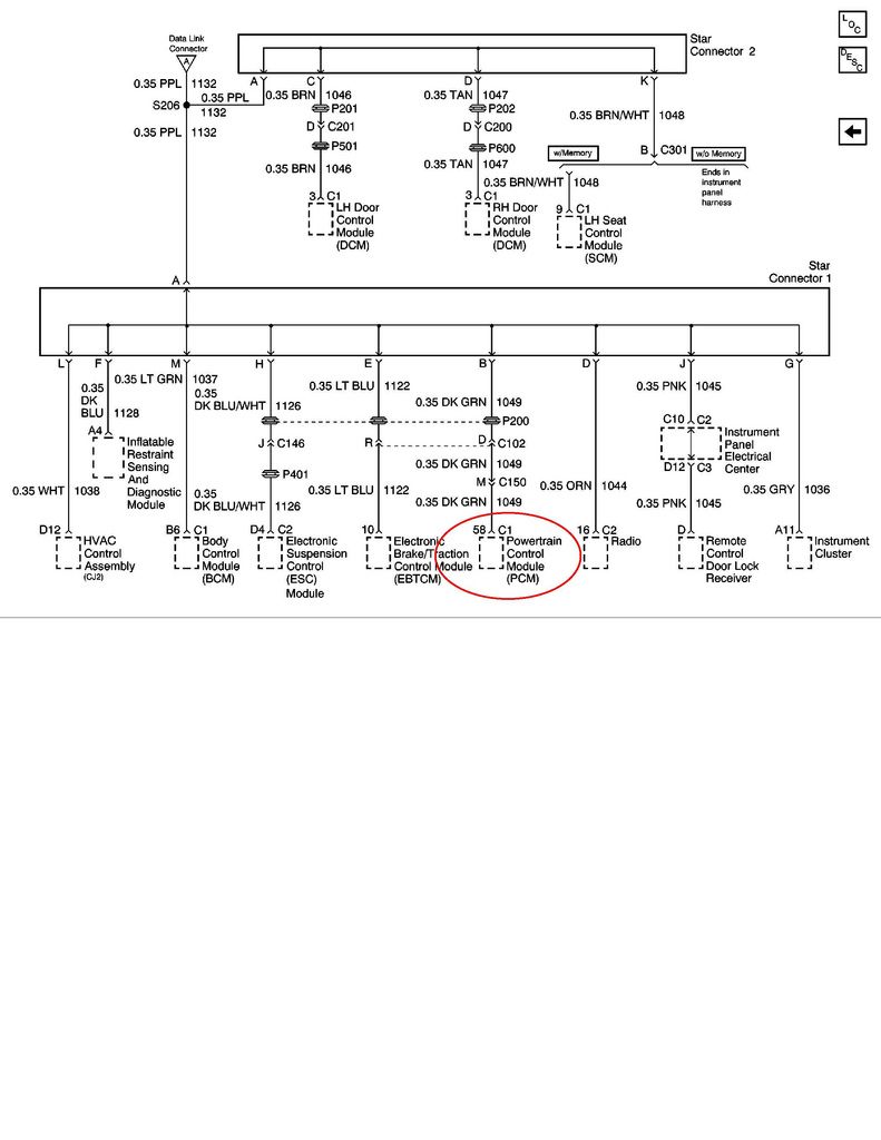
Ok found some inconsistency with the light blue wire running from pin 10 on ecbm to pin E on the star connector 1 whilst doing a continuity check again.. does this wire run straight to the ecbm or does it have any junctions etc etc . Help!!
Instructor
Joined: May 2008
Posts: 218
Likes: 0
From: LA from the 6th sept till the 10th sept california ( then New Zealand)
OK after studying the wiring schematics it seems there is a connection and possibly a solder joint . does anyone know where the connection is?
I Am now getting a reading on the pin 10 to pin E star bus of OL or open circuit. !!
bridged the connection with a temp solderderd wire which closed the poen circuit , turned on the ignition and still TCS NO COMM . what the hell is going on? apart from this issue every thing on the Vette is fine!!
would like to find the connection still !!

Tech Contributor


Joined: Dec 1999
Posts: 32,910
Likes: 2,402
From: Anthony TX
CI 6,7,8,9,11 Vet
St. Jude Donor '08

The DIGITAL information for the EBTCM is not getting to the BCM or the data from the BCM is not getting to the EBTCM.
You either have an OPEN in the Serial Data wire between the EBTCM and the BCM or SHORT or both//
Disconnect the the BCM and the EBTCM.. Check the BCM and the EBTCM end for continuity. Should be zero ohms... Check both ends to GROUND Should be INFINITY
Post results
Instructor
Joined: May 2008
Posts: 218
Likes: 0
From: LA from the 6th sept till the 10th sept california ( then New Zealand)
thanks bill , let me get this right. apart from the wire running from pin 10 ebtcm to pin E star connector( which is now new after a continuity check ) . what wire do i need to look at BCM to EBTCM ? or are there several? please tell me colour and location pin number etc. 

Corvette Stories
The Best of Corvette for Corvette Enthusiasts

150 hp to 1,250 hp: Every Corvette Generation Compared by the Specs That Matter
Joe Kucinski
8 Coolest Corvette Pace Cars (and Replicas) of All Time
Verdad Gallardo
Top 10 Corvette Engines RANKED by Peak Torque (70+ Years of Muscle!)
Joe Kucinski
Corvette ZR1X Will Be Pacing the Indy 500, And Could Probably Race, Too!
Verdad Gallardo
Top 10 Corvettes Coming to Mecum Indy 2026!
Brett Foote
Top 10 C9 Corvette MUST-HAVES to Fix These C8 Generation Flaws!
Michael S. Palmer
10 Revolutionary 'Corvette Firsts' Most People Don't Know
Joe Kucinski
5 Reasons to Upgrade to an LS6-Powered Corvette; 5 Reasons to Stay LT2
Michael S. Palmer
2027 Corvette vs The World: Every C8 vs Its Closest Competitor
Joe Kucinski
Tech Contributor
Joined: Dec 1999
Posts: 32,910
Likes: 2,402
From: Anthony TX
CI 6,7,8,9,11 Vet
St. Jude Donor '08
This will be the THIRD time Ive either posted or referenced this schematic.
THIS IS THE ONE..
HERE IT IS!!!
ITS ALL YOU NEED!
SUPER FRIDAY SALE!!!!!!!
FREE FREE FREE!!
THREE FOR ONE SALE!!!!!
THIS IS THE ONE..
HERE IT IS!!!
ITS ALL YOU NEED!
SUPER FRIDAY SALE!!!!!!!
FREE FREE FREE!!
THREE FOR ONE SALE!!!!!
Instructor
Joined: May 2008
Posts: 218
Likes: 0
From: LA from the 6th sept till the 10th sept california ( then New Zealand)
sorry bill I did not know you was going to post the same diagram! !
this in not my field of expertise as you can tell.....!
OK do i need to check the STAR to bcm PIN M#???? only this one??
am i looking for continuity ? any other wires i need to check??
sorry to sound so dumb......
this in not my field of expertise as you can tell.....!
OK do i need to check the STAR to bcm PIN M#???? only this one??
am i looking for continuity ? any other wires i need to check??
sorry to sound so dumb......
Race Director


Joined: Apr 2007
Posts: 11,150
Likes: 890
From: South Western Ontario
It's a dark green wire that goes from the star connector 1 to the EBTCM. Disconnect the plugs on both ends then check it. Make sure the connectors on the ends are good and not damaged. Check the continuity and make sure it's connected end to end. Check the wire to ground and make sure it's not grounded.
Instructor
Joined: May 2008
Posts: 218
Likes: 0
From: LA from the 6th sept till the 10th sept california ( then New Zealand)
Instructor
Joined: May 2008
Posts: 218
Likes: 0
From: LA from the 6th sept till the 10th sept california ( then New Zealand)
he mentions Check BCM to EBTCM but is have 3 plugs and lots of wires.... i guess it must be 1 wire from bcm ( not star 1 ) to ebcm .. help!!
Race Director
Joined: Apr 2007
Posts: 11,150
Likes: 890
From: South Western Ontario
Instructor
Joined: May 2008
Posts: 218
Likes: 0
From: LA from the 6th sept till the 10th sept california ( then New Zealand)
The DIGITAL information for the EBTCM is not getting to the BCM or the data from the BCM is not getting to the EBTCM.
You either have an OPEN in the Serial Data wire between the EBTCM and the BCM or SHORT or both//
Disconnect the the BCM and the EBTCM.. Check the BCM and the EBTCM end for continuity. Should be zero ohms... Check both ends to GROUND Should be INFINITY
Post results

Instructor
Joined: May 2008
Posts: 218
Likes: 0
From: LA from the 6th sept till the 10th sept california ( then New Zealand)
Instructor
Joined: May 2008
Posts: 218
Likes: 0
From: LA from the 6th sept till the 10th sept california ( then New Zealand)
TRUST ME!! The ABS FIXER people can NOT fix an internal module logic issue. If you are POSITIVE that you have power to the module and the module is correctly grounded, a NO COMMS issues is caused by one of theses issues:
1. The serial data buss has an issue that is being caused the EBTCM or another module. The modules with the most issues are the LDCM, RDCM and the Seat Control Module SCM. Simply disconnect the STAR 2 Connector shorting buss (on top of the connector) and that will ISOLATE those three modules from the rest of the modules.
2. Plain and simple,,, The module has power and ground but, ITS TOAST!
3. Disconnect STAR 1 and STAR 2 connectors and read each module serial data terminal to chassis ground. If one of the readings is out to lunch, that module is likely the issue.
For the C5 to operate, you really only need the BCM and the PCM.
If you disconnect star 1 & 2 connector shorting busses AND JUMPER WIRE PINS "B" & "M" together the engine will start and run just fine.
If you jumper B, M & "E",,,,,,,,,,,, all the other modules will be out of the circuit and if the EBTCM is working, the NO COMMS issue should NOT be an issue any longer.
If its still an issue, you have an issue internal to the module or with the wire to the STAR CONNECTOR! Do a continuity check from the EBTCM connector " PIN #10 " to star connector #1 Pin "E"
BC
i was looking at the wrong wire
 !!
!!