


Service engine Light is on

Tech Contributor


Joined: Dec 1999
Posts: 32,910
Likes: 2,402
From: Anthony TX
CI 6,7,8,9,11 Vet
St. Jude Donor '08
Your Air Injection Reaction System has an issue. Read the below service manual description amd conduct the test.
Document ID# 672128
2001 Chevrolet/Geo Corvette
--------------------------------------------------------------------------------
DTC P1415 or P1416
Circuit Description
An AIR pump is used on this vehicle to lower tail pipe emissions on start-up. The powertrain control module (PCM) supplies a ground to the AIR pump relay, which energizes the AIR pump.
The PCM monitors the heated oxygen (HO2S) sensor voltages in order to diagnose the AIR system.
During the AIR test the PCM activates the AIR pump during closed loop operation. When the AIR is activated, the PCM monitors the HO2S voltages and the short-term fuel trim values for both banks of the engine. If the AIR system is operating properly, the HO2S voltages should go low, and the short term fuel trim should go high.
If the PCM determines that the HO2S voltages for both banks did not respond as expected during the tests, DTC P0410 sets. If only 1 sensor responded, the PCM sets either a DTC P1415 for bank 1 or P1416 for bank 2 in order to indicate on which bank the AIR system is inoperative.
Conditions for Running the DTC
DTCs P0101-P0103, P0107, P0108, P0112, P0113, P0117, P0118, P0125, P0171-P0175, P0200, P0300, P0335, P0336, P0351-P0358, P0440, P0442, P0443, P0446, P0449, P1120, P1220, P1221, P1258, P1441, and the HO2S DTCs are not set.
The engine is running for more than 30 seconds.
The maximum air flow is 22 g/s.
The air/fuel ratio is 13.125:1
The engine load is less than 40 percent.
The ignition voltage is more than 11.7 volts.
The engine is not operating in the Power Enrichment, the Decel Fuel Shut-off, or the Catalyst Over-Temperature Modes.
The engine speed is more than 850 RPM.
The engine coolant temperature (ECT) is between -10�C (+14�F) and 110�C (230�F).
The intake air temperature (IAT) is between -10�C (+14�F) and 100�C (212�F) .
The fuel system is operating in fuel trim cells 1, 2, 4, 5, or 6.
Conditions for Setting the DTC
The HO2S voltage does not go below 222 mV for 1.3 seconds.
OR
The short-term fuel trim does not change more than a predetermined value.
Action Taken When the DTC Sets
The control module illuminates the malfunction indicator lamp (MIL) when the diagnostic runs and fails.
The control module records the operating conditions at the time the diagnostic fails. The control module stores this information in the Freeze Frame/Failure Records.
Conditions for Clearing the MIL/DTC
The control module turns OFF the malfunction indicator lamp (MIL) after 3 consecutive ignition cycles that the diagnostic runs and does not fail.
A current DTC, Last Test Failed, clears when the diagnostic runs and passes.
A history DTC clears after 40 consecutive warm-up cycles, if no failures are reported by this or any other emission related diagnostic.
Clear the MIL and the DTC with a scan tool.
Diagnostic Aids
Remove any debris from the powertrain control module/throttle actuator control module (PCM/TAC) connector surfaces before servicing the PCM/TAC module. Inspect the PCM/TAC module connector gaskets when diagnosing or replacing the modules. Verify that the gaskets are installed correctly. The gaskets prevent contaminate intrusion into the PCM/TAC modules.
For any test that requires probing the PCM or probing a component harness connector, use the connector test adapter kit J 35616-A . Using this kit prevents damage to the harness or component terminals. Refer to Using Connector Test Adapters in Wiring Systems.
Carbon build-up in the exhaust manifold may restrict the amount of air flow necessary to affect the HO2S voltage. If you suspect this condition, remove the air pipe from the manifold and inspect the passage.
For an intermittent condition, refer to Intermittent Conditions .
Test Description
The number below refers to the step number on the diagnostic table.
A check valve that flows in both directions causes heat damage to the AIR system components.
Step
Action
Values
Yes
No
Schematic Reference: Engine Controls Schematics
1
Did you perform the Diagnostic System Check-Engine Controls?
--
Go to Step 2
Go to Diagnostic System Check - Engine Controls
2
Install a scan tool.
Idle the engine in Closed Loop.
Turn OFF all the accessories.
Monitor the HO2S voltage display for the applicable bank on the Engine 1 Data List using a scan tool.
Enable the AIR system using a scan tool.
Observe and record the HO2S voltage as the AIR system is enabled.
Does the HO2S voltage drop below the specified value?
222 mV
Go to Diagnostic Aids
Go to Step 3
3
Inspect all hoses and pipes for:
Proper connections
Secure clamps are on the pipes and the hoses
No kinks, holes, or pinched hoses/pipes
Components with evidence of heat damage
Did all the above verify to be OK?
--
Go to Step 4
Go to Step 6
4
Disconnect the hose from the applicable check valve.
Enable the AIR system using a scan tool.
Is air present at the hose outlet?
--
Go to Step 7
Go to Step 5
5
Repair the restriction or the blockage in the applicable bank AIR hoses/pipes between the exhaust manifold and the point where the system branches to both sides of the engine.
Did you complete the repair?
--
Go to Step 8
--
6
Repair the condition found.
Did you complete the repair?
--
Go to Step 8
--
7
Replace the applicable check valve. Refer to Secondary Air Injection (AIR) Check Valve/Pipe Replacement - Bank 1 or Secondary Air Injection (AIR) Check Valve/Pipe Replacement - Bank 2 .
Did you complete the replacement?
--
Go to Step 8
--
8
Use a scan tool in order to clear the DTCs.
Turn OFF the ignition for 30 seconds.
Start the engine.
Operate the vehicle within the Conditions for Running the DTC as specified in the supporting text.
Does the DTC run and pass?
--
Go to Step 9
Go to Step 2
9
With a scan tool, observe the stored information, Capture info.
Does the scan tool display any DTCs that you have not diagnosed?
--
Go to Diagnostic Trouble Code (DTC) List
System OK
--------------------------------------------------------------------------------
Document ID# 672128
2001 Chevrolet/Geo Corvette
Document ID# 672128
2001 Chevrolet/Geo Corvette
--------------------------------------------------------------------------------
DTC P1415 or P1416
Circuit Description
An AIR pump is used on this vehicle to lower tail pipe emissions on start-up. The powertrain control module (PCM) supplies a ground to the AIR pump relay, which energizes the AIR pump.
The PCM monitors the heated oxygen (HO2S) sensor voltages in order to diagnose the AIR system.
During the AIR test the PCM activates the AIR pump during closed loop operation. When the AIR is activated, the PCM monitors the HO2S voltages and the short-term fuel trim values for both banks of the engine. If the AIR system is operating properly, the HO2S voltages should go low, and the short term fuel trim should go high.
If the PCM determines that the HO2S voltages for both banks did not respond as expected during the tests, DTC P0410 sets. If only 1 sensor responded, the PCM sets either a DTC P1415 for bank 1 or P1416 for bank 2 in order to indicate on which bank the AIR system is inoperative.
Conditions for Running the DTC
DTCs P0101-P0103, P0107, P0108, P0112, P0113, P0117, P0118, P0125, P0171-P0175, P0200, P0300, P0335, P0336, P0351-P0358, P0440, P0442, P0443, P0446, P0449, P1120, P1220, P1221, P1258, P1441, and the HO2S DTCs are not set.
The engine is running for more than 30 seconds.
The maximum air flow is 22 g/s.
The air/fuel ratio is 13.125:1
The engine load is less than 40 percent.
The ignition voltage is more than 11.7 volts.
The engine is not operating in the Power Enrichment, the Decel Fuel Shut-off, or the Catalyst Over-Temperature Modes.
The engine speed is more than 850 RPM.
The engine coolant temperature (ECT) is between -10�C (+14�F) and 110�C (230�F).
The intake air temperature (IAT) is between -10�C (+14�F) and 100�C (212�F) .
The fuel system is operating in fuel trim cells 1, 2, 4, 5, or 6.
Conditions for Setting the DTC
The HO2S voltage does not go below 222 mV for 1.3 seconds.
OR
The short-term fuel trim does not change more than a predetermined value.
Action Taken When the DTC Sets
The control module illuminates the malfunction indicator lamp (MIL) when the diagnostic runs and fails.
The control module records the operating conditions at the time the diagnostic fails. The control module stores this information in the Freeze Frame/Failure Records.
Conditions for Clearing the MIL/DTC
The control module turns OFF the malfunction indicator lamp (MIL) after 3 consecutive ignition cycles that the diagnostic runs and does not fail.
A current DTC, Last Test Failed, clears when the diagnostic runs and passes.
A history DTC clears after 40 consecutive warm-up cycles, if no failures are reported by this or any other emission related diagnostic.
Clear the MIL and the DTC with a scan tool.
Diagnostic Aids
Remove any debris from the powertrain control module/throttle actuator control module (PCM/TAC) connector surfaces before servicing the PCM/TAC module. Inspect the PCM/TAC module connector gaskets when diagnosing or replacing the modules. Verify that the gaskets are installed correctly. The gaskets prevent contaminate intrusion into the PCM/TAC modules.
For any test that requires probing the PCM or probing a component harness connector, use the connector test adapter kit J 35616-A . Using this kit prevents damage to the harness or component terminals. Refer to Using Connector Test Adapters in Wiring Systems.
Carbon build-up in the exhaust manifold may restrict the amount of air flow necessary to affect the HO2S voltage. If you suspect this condition, remove the air pipe from the manifold and inspect the passage.
For an intermittent condition, refer to Intermittent Conditions .
Test Description
The number below refers to the step number on the diagnostic table.
A check valve that flows in both directions causes heat damage to the AIR system components.
Step
Action
Values
Yes
No
Schematic Reference: Engine Controls Schematics
1
Did you perform the Diagnostic System Check-Engine Controls?
--
Go to Step 2
Go to Diagnostic System Check - Engine Controls
2
Install a scan tool.
Idle the engine in Closed Loop.
Turn OFF all the accessories.
Monitor the HO2S voltage display for the applicable bank on the Engine 1 Data List using a scan tool.
Enable the AIR system using a scan tool.
Observe and record the HO2S voltage as the AIR system is enabled.
Does the HO2S voltage drop below the specified value?
222 mV
Go to Diagnostic Aids
Go to Step 3
3
Inspect all hoses and pipes for:
Proper connections
Secure clamps are on the pipes and the hoses
No kinks, holes, or pinched hoses/pipes
Components with evidence of heat damage
Did all the above verify to be OK?
--
Go to Step 4
Go to Step 6
4
Disconnect the hose from the applicable check valve.
Enable the AIR system using a scan tool.
Is air present at the hose outlet?
--
Go to Step 7
Go to Step 5
5
Repair the restriction or the blockage in the applicable bank AIR hoses/pipes between the exhaust manifold and the point where the system branches to both sides of the engine.
Did you complete the repair?
--
Go to Step 8
--
6
Repair the condition found.
Did you complete the repair?
--
Go to Step 8
--
7
Replace the applicable check valve. Refer to Secondary Air Injection (AIR) Check Valve/Pipe Replacement - Bank 1 or Secondary Air Injection (AIR) Check Valve/Pipe Replacement - Bank 2 .
Did you complete the replacement?
--
Go to Step 8
--
8
Use a scan tool in order to clear the DTCs.
Turn OFF the ignition for 30 seconds.
Start the engine.
Operate the vehicle within the Conditions for Running the DTC as specified in the supporting text.
Does the DTC run and pass?
--
Go to Step 9
Go to Step 2
9
With a scan tool, observe the stored information, Capture info.
Does the scan tool display any DTCs that you have not diagnosed?
--
Go to Diagnostic Trouble Code (DTC) List
System OK
--------------------------------------------------------------------------------
Document ID# 672128
2001 Chevrolet/Geo Corvette

Thread Starter
Intermediate

Joined: Mar 2011
Posts: 32
Likes: 0
From: Columbus Georgia
Wow. thats a lot of steps. What all do I need to do it? I see a scan tool is needed. I don't have one. And where in the car is all of this stuff located? And pictures would be nice. Thanks.
Drifting


Joined: Jul 2006
Posts: 1,490
Likes: 257
From: Lake Tapps WA.
By the way, you can clear the code yourself. When you run your codes and get to the 1416 push the "reset" button on the DIC. It will come back of course if you don't fix it.
Last edited by C5FORFUN2; Dec 3, 2012 at 08:31 PM.
Tech Contributor
Joined: Dec 1999
Posts: 32,910
Likes: 2,402
From: Anthony TX
CI 6,7,8,9,11 Vet
St. Jude Donor '08
That my friend is why you need to invest in a set of service manuals.
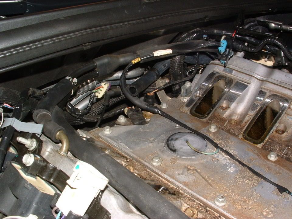
If you look at the write up it states that NEITHER bank is reading a change in air flow (O2 sensor values) when the pump runs,,, SO,, the AIR pump is either not working, not supplying air or the control valve is not letting air out of the pump.
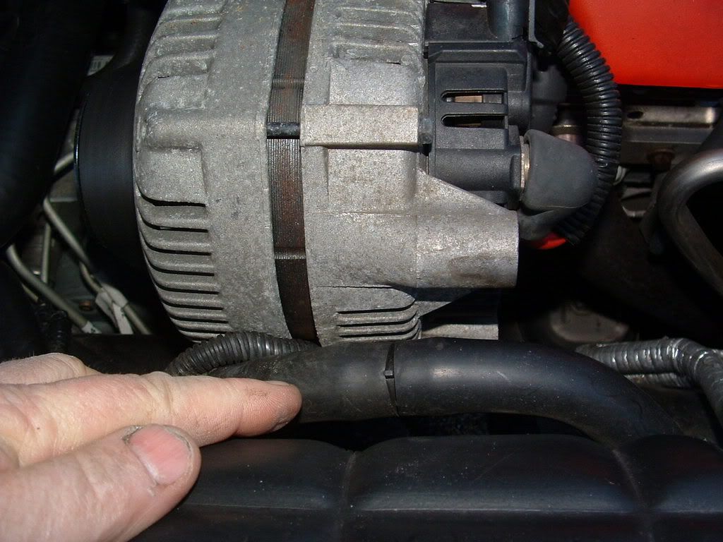
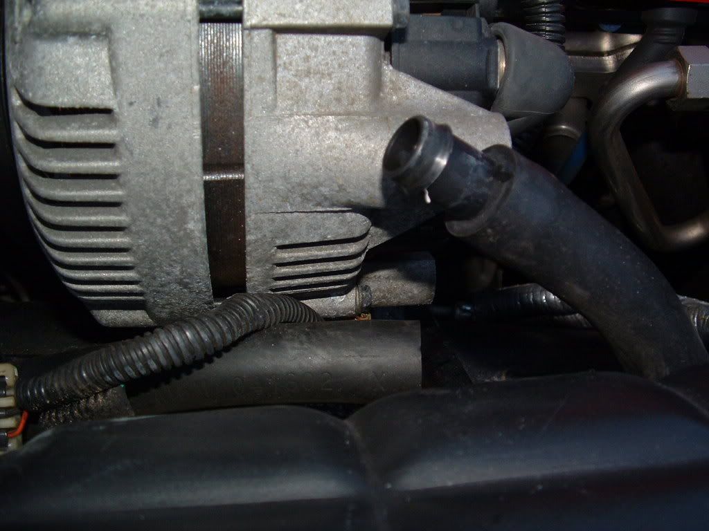
Outboard of the alternator is a 1" rubber hose. Its split and connected with a plactic coupler. Disconnect it and start the engine COLD. You should feel LOTS of air coming out of the pipe that comes from the pump: (lower most pipe)
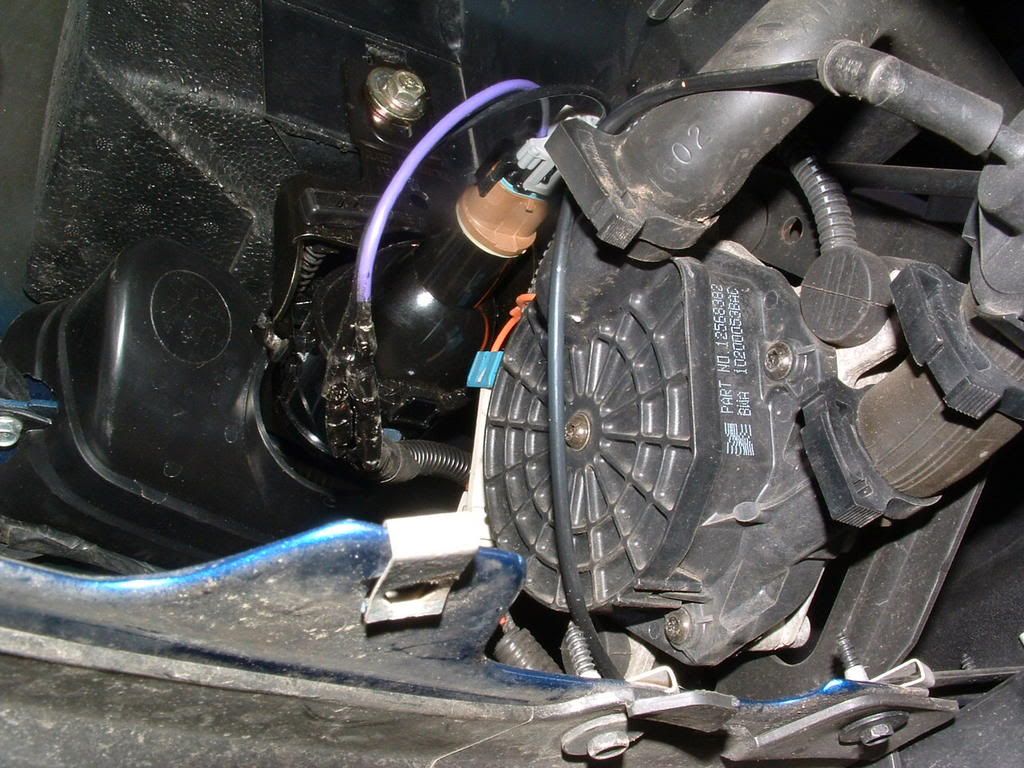
This is the A.I. R pump, and vacuum controlled outlet valve located under the drivers headlight:.

If you look at the write up it states that NEITHER bank is reading a change in air flow (O2 sensor values) when the pump runs,,, SO,, the AIR pump is either not working, not supplying air or the control valve is not letting air out of the pump.
Outboard of the alternator is a 1" rubber hose. Its split and connected with a plactic coupler. Disconnect it and start the engine COLD. You should feel LOTS of air coming out of the pipe that comes from the pump: (lower most pipe)
This is the A.I. R pump, and vacuum controlled outlet valve located under the drivers headlight:.
Tech Contributor
Joined: Dec 1999
Posts: 32,910
Likes: 2,402
From: Anthony TX
CI 6,7,8,9,11 Vet
St. Jude Donor '08
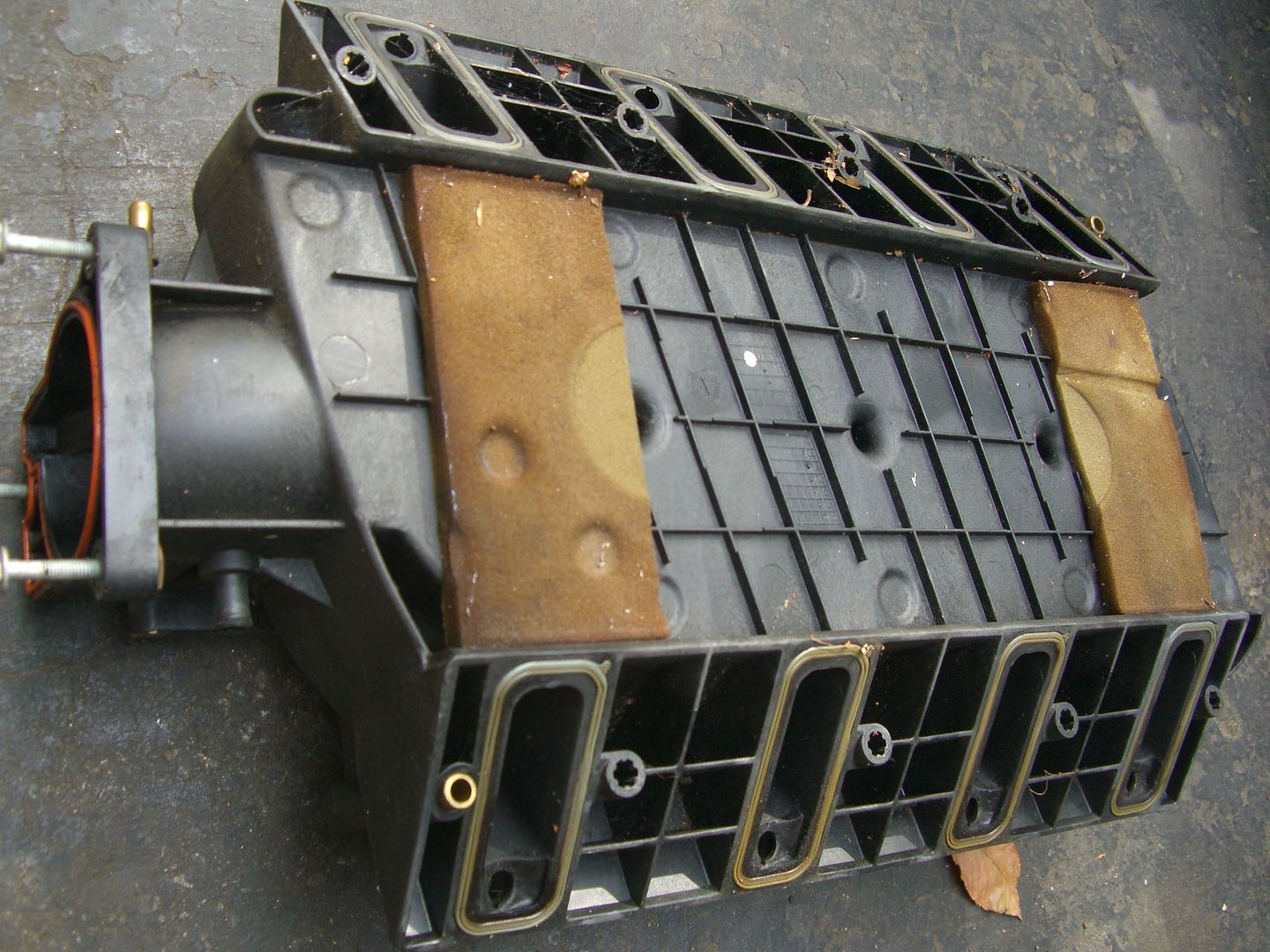
Passenger side AIR check valve is stuck closed. Seems to always happen on that side. On the F body LS1 at least the valve was on the exh. manifold like the drivers side, but on the C5 it's buried behind the intake manifold. So you can either tear it apart and replace the valve or just take it to a tuner (I used HP Tuners program myself) and have them set the AIR codes to not report. It does not effect the car or set any more codes.
By the way, you can clear the code yourself. When you run your codes and get to the 1416 push the "reset" button on the DIC. It will come back of course if you don't fix it.
By the way, you can clear the code yourself. When you run your codes and get to the 1416 push the "reset" button on the DIC. It will come back of course if you don't fix it.
 1416 is one ( behind the intake manifold) stuck shut.
Corvette Stories
The Best of Corvette for Corvette Enthusiasts

Top 10 Most Expensive Corvettes Ever Sold on Bring A Trailer
Brett Foote
10 Things Every Corvette Owner Needs (2026 Edition)
Michael S. Palmer
8 Most "Only Corvette Owners Understand" Quirks and Problems
Pouria Savadkouei
10 Reasons the C6 Z06 is Still A Performance Benchmark After 20 Years
Joe Kucinski
How Much Horsepower Every Corvette Engine "LOST" in 1972
Joe Kucinski
Top 10 DOs and DON'Ts for Protecting Your Convertible Top!
Michael S. Palmer
Top 10 Most Explosive Corvettes Ever Made: Power-to-Weight Ratio Ranked!
Joe Kucinski
150 hp to 1,250 hp: Every Corvette Generation Compared by the Specs That Matter
Joe Kucinski
8 Coolest Corvette Pace Cars (and Replicas) of All Time
Verdad Gallardo
Thread Starter
Intermediate
Joined: Mar 2011
Posts: 32
Likes: 0
From: Columbus Georgia
Where's the best place to buy the passenger check valve and an oil pressure sensor? And how much are we talkin?
Also, what's the best way to get the intake covers off without destroying them in the process?
And does anyone have pics of the whole disassemble process? it would be very helpful. Thanks.
Also, what's the best way to get the intake covers off without destroying them in the process?
And does anyone have pics of the whole disassemble process? it would be very helpful. Thanks.
Safety Car


Joined: Dec 2004
Posts: 3,738
Likes: 217
From: Arizona AZ
I posted this link on another thread regarding the p1416 code. I have it too.
This link contains other links, it also can tell you how to pull codes from your Driver Information Center DIC........I suggest a lot of reading....then make your call as to HOW to fix it. There's Bill Curlees way which is a temporary fix, then there's an alternative way, then there's the purist way.
Do your homework on this AND the oil pressure sending unit. There's a relocation fix for the oil sending unit and then there a relocation way for the check valve causing the P1416 code.
So....join the crowd, the P1416 is one that haunts many C5s and the Gm engineers didn't so us any favors when they deigned it to be bolted BEHIND the block.
Here's the link:
http://forums.corvetteforum.com/c5-t...1416-code.html
Tech Contributor
Joined: Dec 1999
Posts: 32,910
Likes: 2,402
From: Anthony TX
CI 6,7,8,9,11 Vet
St. Jude Donor '08
When the AIR Check valve first started giving C5 owners issues, I tried to provide an easy fix. Hey,, it worked but some found out that the fix was a temp band aid.
I dissected one and found out why. The diaphragm is rubber and as it ages it gets hard and stiff and soon prevents air flow.

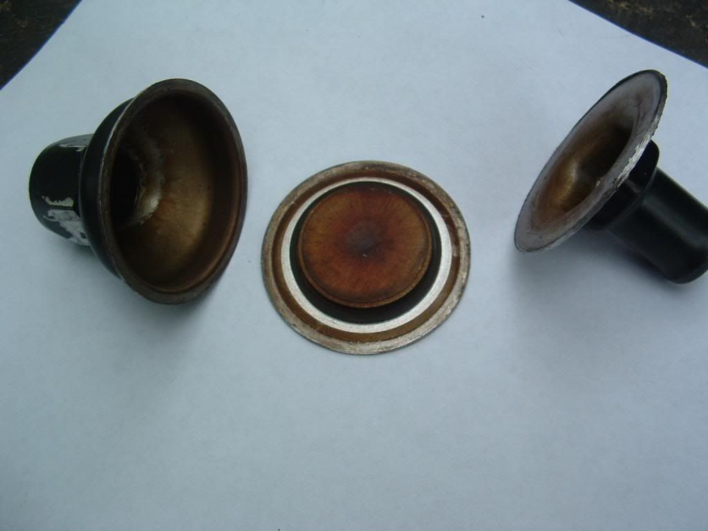

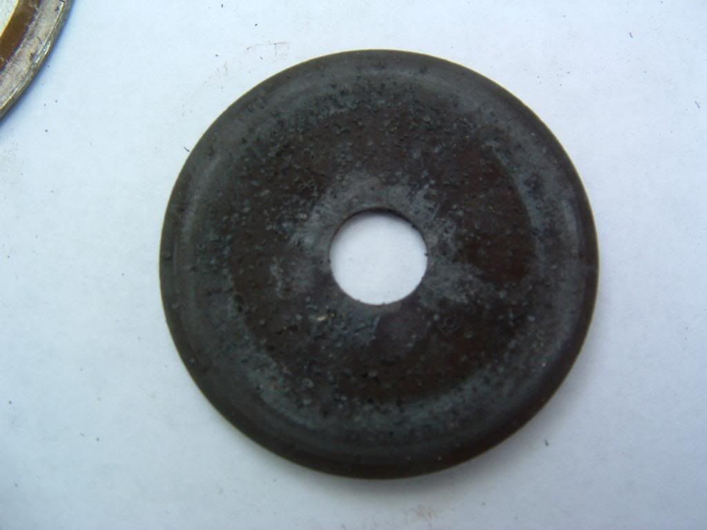
Simplest and most effective repair is to change the valve.
I dissected one and found out why. The diaphragm is rubber and as it ages it gets hard and stiff and soon prevents air flow.
Simplest and most effective repair is to change the valve.
Thread Starter
Intermediate
Joined: Mar 2011
Posts: 32
Likes: 0
From: Columbus Georgia
Should I unhook the battery before disconnecting any of the wired connections?
I picked up my new check valve and intake manifold gaskets today. Had to order the new oil sending unit, will be in Thursday morning. Then its time for the fun part of changing it all out. Yeah!!!!!
Thanks guys for all your help. Your the best.
I picked up my new check valve and intake manifold gaskets today. Had to order the new oil sending unit, will be in Thursday morning. Then its time for the fun part of changing it all out. Yeah!!!!!
Thanks guys for all your help. Your the best.
Thread Starter
Intermediate
Joined: Mar 2011
Posts: 32
Likes: 0
From: Columbus Georgia
I know this is going to sound stupid, But, How do i get in to clear the fault code? I did it once or i couldn't find the P1416 code. but i forgot what i did. Please help. and thanks..
Tech Contributor
Joined: Dec 1999
Posts: 32,910
Likes: 2,402
From: Anthony TX
CI 6,7,8,9,11 Vet
St. Jude Donor '08
READING YOUR Engine Diagnostic Codes (DTCs)
The Diagnostic Display Mode is entered with the following procedure:
1) Turn on the ignition but don't start the engine.
2) Press the RESET button to turn off any warning messages. (i.e. door open, trunk open etc�)
3) Press and hold OPTIONS
4) While holding OPTIONS, press FUEL four times within a 10-second period.
Initially, on-board diagnostics go into an Automatic Mode which shows diagnostic codes in a pre-set sequence: PCM - TCS - RTD - BCM - IPC - RADIO - HVAC - LDCM - RDCM - SCM - RFA. All codes will be displayed for each. ( i.e. PCM = 4 codes)
If none are present in a given module, you will see No More Codes on the display.
There are two kinds of diagnostic codes, Current and History designated with a letter suffix, C or ;H. A current code indicates a malfunction is present in the module displaying data. A history code indicates a problem existed sometime in the last 40 or 50 ignition cycles. When not accompanied by a current code of the same number, it's potential evidence of a previous problem, now resolved, that was not removed by clearing the codes.
More likely it's an indication of an intermittent malfunction.
Intermittent codes are the most challenging of the diagnostics. An intermittent code may have happened once, may have happened more than once but is inconsistent or may be happening on a regular basis but not at the time the codes are displayed. History codes can also be caused by a current malfunction in a system that is not operating at the time codes are displayed. An example is the rear window defogger which doesn't operate until the Body Control Module detects engine rpm. For history codes set by a module that does not operate with the key on and engine off, a special diagnostic tool called a Scan Tester is necessary to properly diagnose the malfunction.
Once the system has displayed all modules, it goes into the manual mode which allows selection of each module using combinations of Driver Information Center buttons. Manual mode can also be entered during the automatic sequence by pressing any button except E/M. Once the display shows Manual Diagnostics, select a module by pressing the OPTIONS button to go forward or the TRIP button to go back. Once a module is selected, a code is displayed, and if more than one are present;
press GAGES to go forward or FUEL to go back.
To exit the diagnostic mode at any time, press E/M. If you want to erase codes in a given module, press RESET
To reset the codes once in manual mode, press and hold RESET until it displays NO CODES Press OPTIONS to go to the next module. Repeat the steps until you have reset the codes in all the computer modules.
NOTE!! Only reset the codes IF you want to - it is NOT necessary to do this. Clearing a code does not repair a problem. You are simply erasing the evidence of it in the module's memory. If you clear the code/s, and extinguish the Check Engine Light, your emissions status ready will NOT allow you to pass an emissions test until you have completed the required driving cycles.
Once you have the codes, the next question is: What to do with the information?
First, consult the factory service manual. Any serious C5 Do-It-Yourself owner should invest in the Corvette Service Manual of the appropriate model year. The Service Manual is really a requirement if you want to understand and work on your C5.
Here is very good site of DTC definitions:
http://www.gearchatter.com
Make sure to include the H or C suffix!!
Thread Starter
Intermediate
Joined: Mar 2011
Posts: 32
Likes: 0
From: Columbus Georgia
Job is done! Replaced oil pressuresensor and air chaeck valve. Cleared code. Took it for a drive. Runs great.
Now I have a Vacuum leak or something I checked all the hoses and all are plugged in even the one on the back of the intake manifold.
What else could this be?
Now I have a Vacuum leak or something I checked all the hoses and all are plugged in even the one on the back of the intake manifold.
What else could this be?
Safety Car
Joined: Dec 2004
Posts: 3,738
Likes: 217
From: Arizona AZ
Job is done! Replaced oil pressuresensor and air chaeck valve. Cleared code. Took it for a drive. Runs great.
Now I have a Vacuum leak or something I checked all the hoses and all are plugged in even the one on the back of the intake manifold.
What else could this be?
Now I have a Vacuum leak or something I checked all the hoses and all are plugged in even the one on the back of the intake manifold.
What else could this be?
I still haven't pulled my intake so all I'm doing is passing along what I read. I'm sure someone will be able to chime in with some ideas, probably a lot better informed than I am but I thought I'd just post what I've read so far.
Congrats on the repair, let's hope it's an easy fix now.