


HUD Install -- DIY Master Thread
Thread Starter
Running Guns & Moonshine
Joined: Aug 2001
Posts: 12,448
Likes: 7,152
From: CT
Sorry, for right now I'm just putting this out there. I'll come back to edit and add pictures and detailed info.
I will put up links to those who came before me which helped me immensely.
I had just finished an OCD session installing new custom Gauge Overlays from Jeff (Xtremevette) when I finally thought to look for the HUD plug on the back of the cluster from my '99. Some threads said that the '99s were hit or miss. Other authorities said '99s pretty much all had HUD enabled clusters, so don't sweat it. Mine? After several hours of detailed work on the gauges, I had that quiet moment where your only thought is.... shhhhoot... No connector.
Now, most of the install info I used came from Vette Essentials and this thread on the forum here which was extremely helpful:
http://forums.corvetteforum.com/c5-t...d-install.html
When I discovered I had a non-HUD enabled cluster, I managed to find this unique post which gave me hope. MANY thanks to PLYFSTR, who came and went from the forums:
http://forums.corvetteforum.com/c5-g...l?forum_id=103
When I found the thread above, I quickly searched for anything else he may have posted which could have had the details he was going to share. In reading other threads, I believe the very day after accomplishing the wiring his car was wrecked and he left the forums not long after.
When I get the pictures and other links together, I'll post them here.
For now, know that non-HUD clusters CAN have connectors soldered in and they DO work flawlessly.
Enabling the Cluster for HUD:
Note --> This worked on my 1999 cluster. PLYFSTR's car was also a 1999. I don't know if the boards are the same on 97 and 98 cars. If someone tries this project on one of those cars, PLEASE come back and share your experience as to whether it works or not so others will know.
You will need a solder gun, preferably temperature controlled.
I used .022" (.559mm) diameter lead-free solder from Radioshack
I purchased a 40-pin 0.1" single row which I broke down to the 8-pin needed
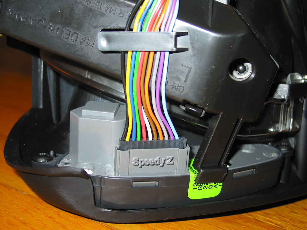
The great thing is that this is relatively easy. However, if you have no experience with soldering I suggest having someone experienced do it for you or practicing on junk boards first. All I did was take the 8-pin connector, apply some solder beads to the short tip ends, then held it in place over the positions on the board where the HUD connector should be. The 8-pins used, when viewing the cluster from behind, should begin on your LEFT. You will have two unused. So again, they begin from what is the passenger side of the car. Once the connector is held in the right place, I then went back and melted the bead on each pin so it made a solid connection to the board. For those with less experience, the key is to have each bead be separate from it's neighbor -- no overlapping beads!
And that.... is all there is to it. I put my soldered 8-pin in place such that the plastic barrier also rested on the cluster board... this has the open pins at an angle of about 40 degrees from the board... not the 90 degrees of the factory unit. Simply install the cluster, plug in the HUD's wire to this new 8-pin piece and you are live.
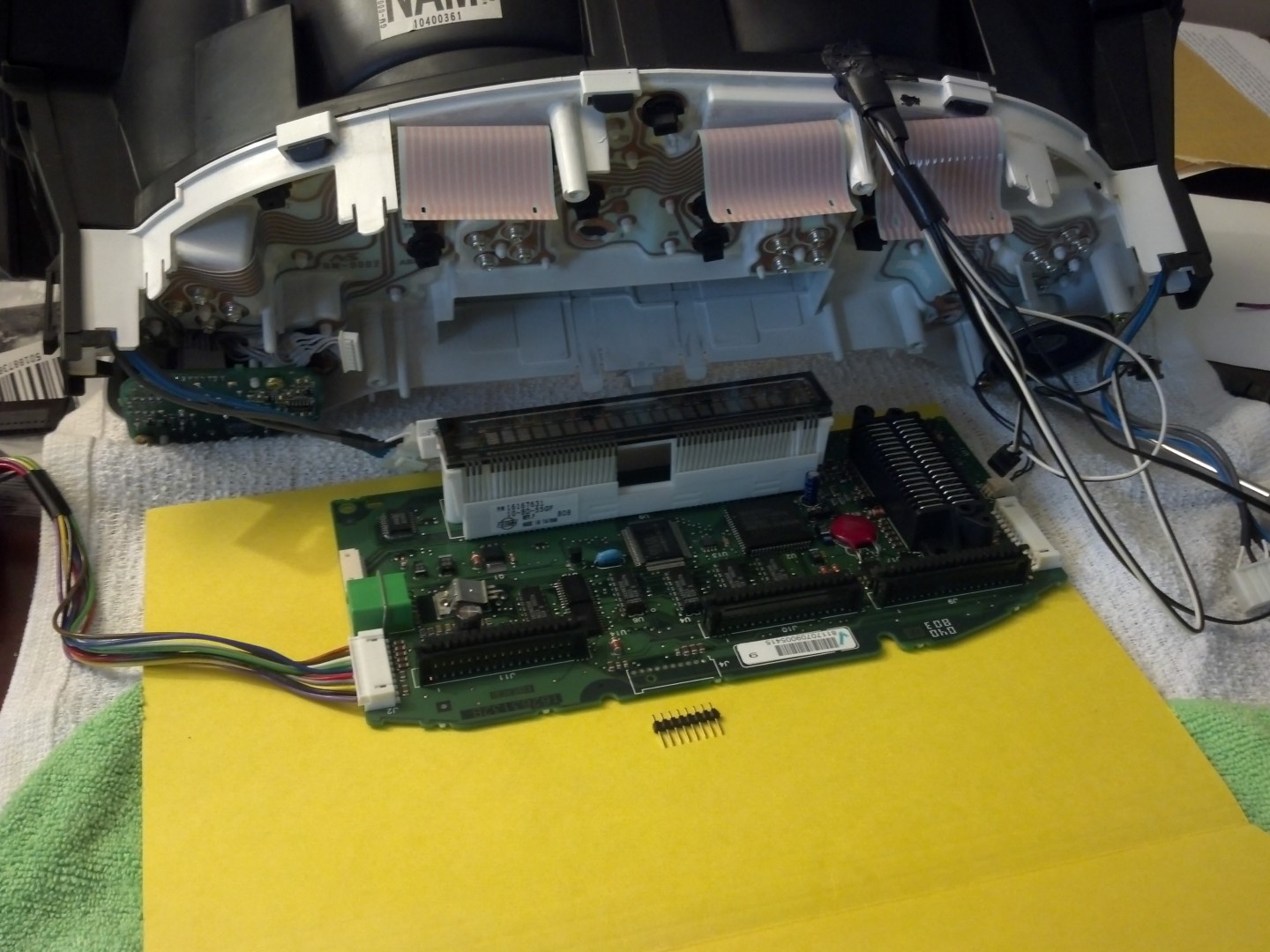
Here is the back of the cluster in general. The group of wires coming out of the top are for lighting the custom gauges.
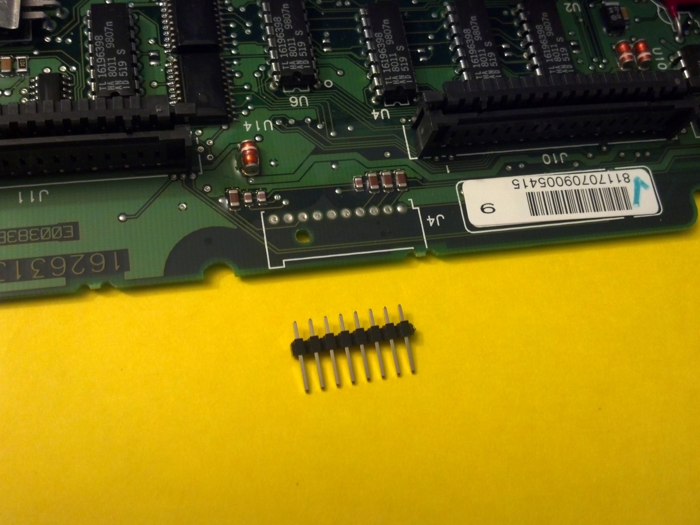
A closer view of the 8-pin piece I used and the 10 connecting points on the board
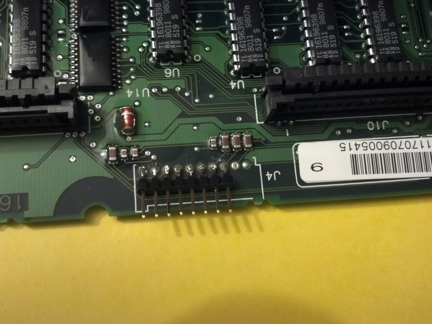
A very close view of my embarrassingly poor soldering skills -- but it still works! [Edit: Late 2019 now and the HUD continues to work as though installed from the factory.]
HUD bezel cable:
You will need to get some 22 gauge wires
A wiring multi-tool
A crimper specific to the wire-end connectors
Female pins for the cluster and bezel ends (Cluster - I bought JHS 2.50mm female pins from a local electronics shop) (Bezel - have to hunt down the link)
The correct plastic connector for the bezel end (Will hunt down the correct link)
I had an older thread from when I was collecting parts and researching: http://forums.corvetteforum.com/c5-t...cable-new.html
The work here is easy. Just basic wiring. Cut the new wires to match existing ones. Transfer existing wires to the new, larger bezel connector and then install the four new wires at both ends.
I grabbed these two pictures from a Google search just now, but I know I have seen them in a thread on the forums here before. If you let me know who put them up, I will give them direct credit.
The first image is of the Cluster end of the HUD cable. It shows the required wires. The red wire is at the TOP of the cluster.
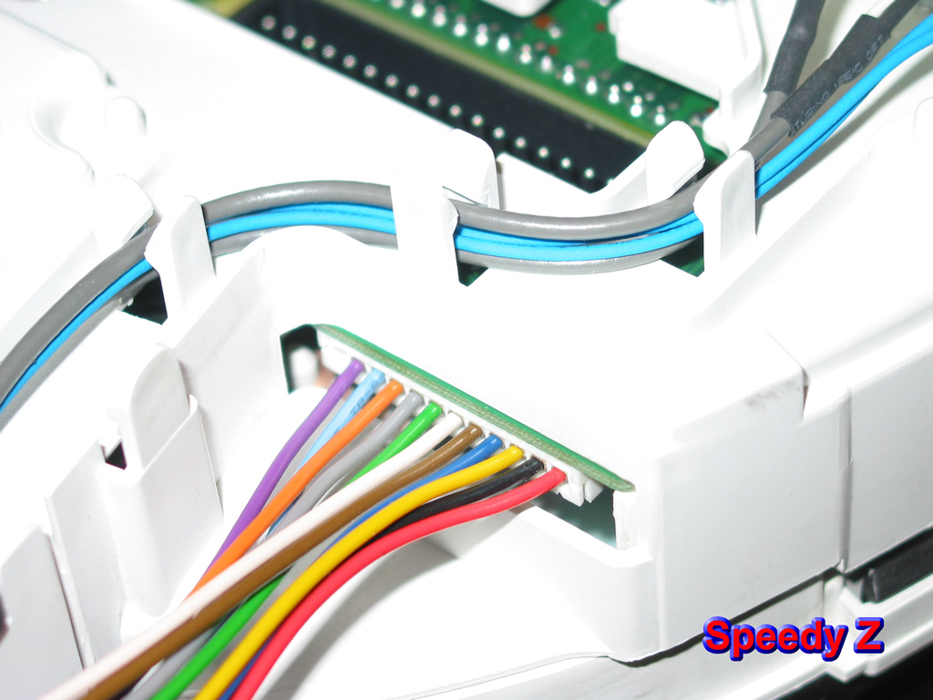
This second image shows the wiring at the HUD bezel. The empty slot is at the top, and then the Light Blue.
If you're like me, you may end up using just one color of 22ga wire to make your connections. Not the best procedure, but it works. So here is a color code of how to make your own wire loom. I also attach numbers for the thrifty souls like myself.
Cluster (top to bottom)
1 red
2 black
3 yellow
4 blue
5 brown
6 white
7 green
8 grey
9 orange
10 light blue
11 purple
12 ** empty **
HUD bezel (top to bottom)
12 ** empty **
10 light blue
11 purple
8 grey
9 orange
5 brown
6 white
1 red
7 green
4 blue
3 yellow
2 black
The only thing I would suggest people continue to seek out is the proper matching female pin connectors for us at the cluster side of the wires. What I used fit correctly and worked, but I had to take a narrow set of forceps and plunge one tip into the front of each of the four new connections and "spread them out." Without this, they would not easily slip onto the cluster pins. Likewise, the little locking tabs were not strong. I had to very carefully bend the tip end only on each of the lock tabs to hold the pieces in place inside the factory connector. This problem was probably exaggerated by the tight fitting pins which wanted to push the new fittings out the back. I got it to work fine, but I know having the fully correct part will make it easier.
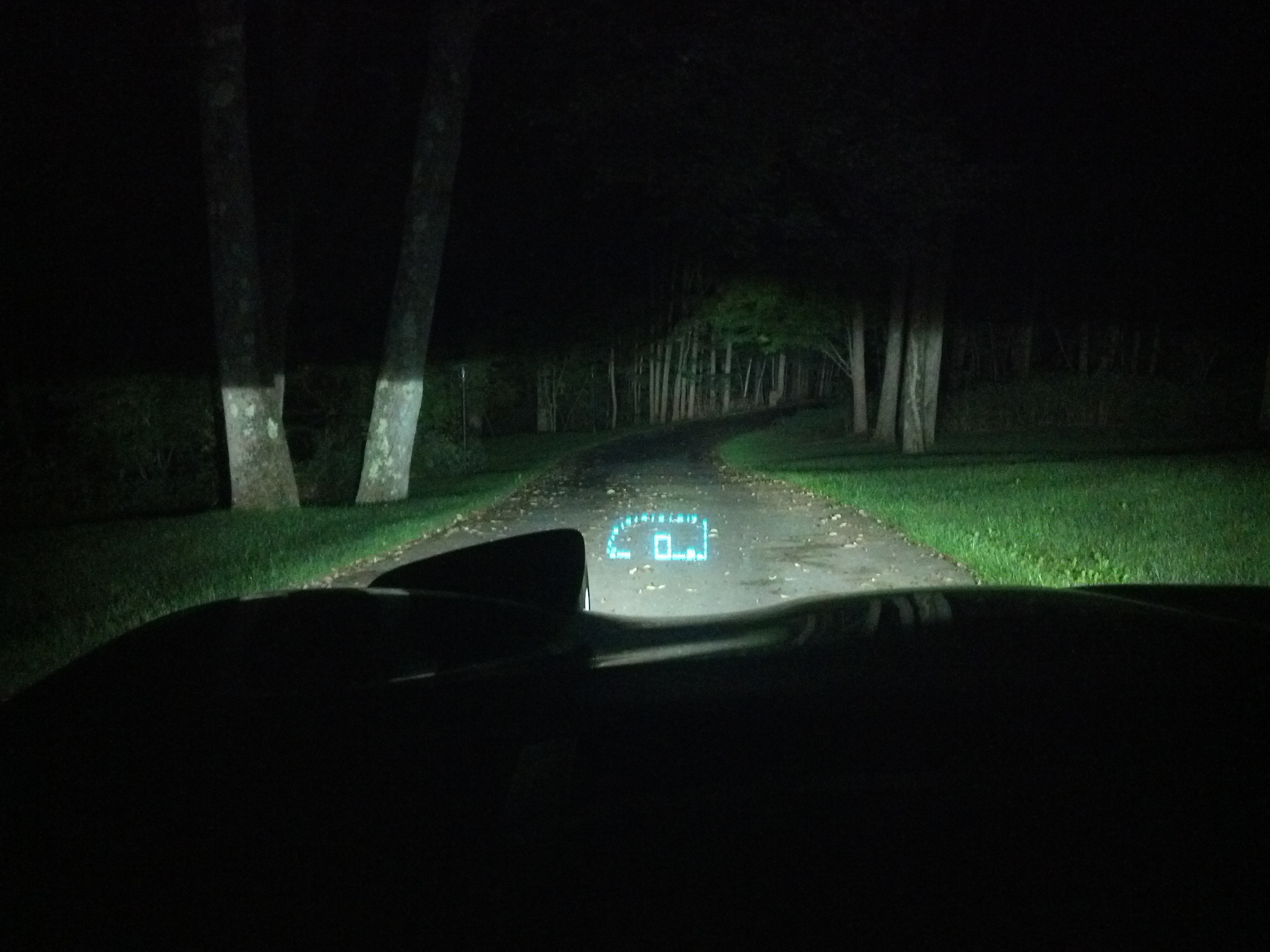
I need to finalize some wiring for the Overlays I installed and am waiting for the correct size red LEDs to arrive for the HUD bezel. When that is settled, I will do more than a ten minute loose installation test and confirm everything is rocking. The quick test showed all functions working 100% on the HUD. Dim, Bright, Page, and Display Position.
Proof of functioning taken tonight 9/3/13
I will put up links to those who came before me which helped me immensely.
I had just finished an OCD session installing new custom Gauge Overlays from Jeff (Xtremevette) when I finally thought to look for the HUD plug on the back of the cluster from my '99. Some threads said that the '99s were hit or miss. Other authorities said '99s pretty much all had HUD enabled clusters, so don't sweat it. Mine? After several hours of detailed work on the gauges, I had that quiet moment where your only thought is.... shhhhoot... No connector.
Now, most of the install info I used came from Vette Essentials and this thread on the forum here which was extremely helpful:
http://forums.corvetteforum.com/c5-t...d-install.html
When I discovered I had a non-HUD enabled cluster, I managed to find this unique post which gave me hope. MANY thanks to PLYFSTR, who came and went from the forums:
http://forums.corvetteforum.com/c5-g...l?forum_id=103
When I found the thread above, I quickly searched for anything else he may have posted which could have had the details he was going to share. In reading other threads, I believe the very day after accomplishing the wiring his car was wrecked and he left the forums not long after.
When I get the pictures and other links together, I'll post them here.
For now, know that non-HUD clusters CAN have connectors soldered in and they DO work flawlessly.
Enabling the Cluster for HUD:
Note --> This worked on my 1999 cluster. PLYFSTR's car was also a 1999. I don't know if the boards are the same on 97 and 98 cars. If someone tries this project on one of those cars, PLEASE come back and share your experience as to whether it works or not so others will know.
You will need a solder gun, preferably temperature controlled.
I used .022" (.559mm) diameter lead-free solder from Radioshack
I purchased a 40-pin 0.1" single row which I broke down to the 8-pin needed
The great thing is that this is relatively easy. However, if you have no experience with soldering I suggest having someone experienced do it for you or practicing on junk boards first. All I did was take the 8-pin connector, apply some solder beads to the short tip ends, then held it in place over the positions on the board where the HUD connector should be. The 8-pins used, when viewing the cluster from behind, should begin on your LEFT. You will have two unused. So again, they begin from what is the passenger side of the car. Once the connector is held in the right place, I then went back and melted the bead on each pin so it made a solid connection to the board. For those with less experience, the key is to have each bead be separate from it's neighbor -- no overlapping beads!
And that.... is all there is to it. I put my soldered 8-pin in place such that the plastic barrier also rested on the cluster board... this has the open pins at an angle of about 40 degrees from the board... not the 90 degrees of the factory unit. Simply install the cluster, plug in the HUD's wire to this new 8-pin piece and you are live.
Here is the back of the cluster in general. The group of wires coming out of the top are for lighting the custom gauges.
A closer view of the 8-pin piece I used and the 10 connecting points on the board
A very close view of my embarrassingly poor soldering skills -- but it still works! [Edit: Late 2019 now and the HUD continues to work as though installed from the factory.]
HUD bezel cable:
You will need to get some 22 gauge wires
A wiring multi-tool
A crimper specific to the wire-end connectors
Female pins for the cluster and bezel ends (Cluster - I bought JHS 2.50mm female pins from a local electronics shop) (Bezel - have to hunt down the link)
The correct plastic connector for the bezel end (Will hunt down the correct link)
I had an older thread from when I was collecting parts and researching: http://forums.corvetteforum.com/c5-t...cable-new.html
The work here is easy. Just basic wiring. Cut the new wires to match existing ones. Transfer existing wires to the new, larger bezel connector and then install the four new wires at both ends.
I grabbed these two pictures from a Google search just now, but I know I have seen them in a thread on the forums here before. If you let me know who put them up, I will give them direct credit.
The first image is of the Cluster end of the HUD cable. It shows the required wires. The red wire is at the TOP of the cluster.
This second image shows the wiring at the HUD bezel. The empty slot is at the top, and then the Light Blue.
If you're like me, you may end up using just one color of 22ga wire to make your connections. Not the best procedure, but it works. So here is a color code of how to make your own wire loom. I also attach numbers for the thrifty souls like myself.
Cluster (top to bottom)
1 red
2 black
3 yellow
4 blue
5 brown
6 white
7 green
8 grey
9 orange
10 light blue
11 purple
12 ** empty **
HUD bezel (top to bottom)
12 ** empty **
10 light blue
11 purple
8 grey
9 orange
5 brown
6 white
1 red
7 green
4 blue
3 yellow
2 black
The only thing I would suggest people continue to seek out is the proper matching female pin connectors for us at the cluster side of the wires. What I used fit correctly and worked, but I had to take a narrow set of forceps and plunge one tip into the front of each of the four new connections and "spread them out." Without this, they would not easily slip onto the cluster pins. Likewise, the little locking tabs were not strong. I had to very carefully bend the tip end only on each of the lock tabs to hold the pieces in place inside the factory connector. This problem was probably exaggerated by the tight fitting pins which wanted to push the new fittings out the back. I got it to work fine, but I know having the fully correct part will make it easier.
I need to finalize some wiring for the Overlays I installed and am waiting for the correct size red LEDs to arrive for the HUD bezel. When that is settled, I will do more than a ten minute loose installation test and confirm everything is rocking. The quick test showed all functions working 100% on the HUD. Dim, Bright, Page, and Display Position.
Proof of functioning taken tonight 9/3/13
Last edited by Tusc; Sep 15, 2019 at 10:56 PM.
Team Owner

Joined: Jul 2012
Posts: 34,479
Likes: 532
From: Central PA. - - My AR15 identifies as a muzzleloader
I believe in the Beer Fairy
Note --> This worked on my 1999 cluster. PLYFSTR's car was also a 1999. I don't know if the boards are the same on 97 and 98 cars. If someone tries this project on one of those cars, PLEASE come back and share your experience as to whether it works or not so others will know.
THANKS for the GREAT info and great pics. Helped me to make my control cable using 2 of the old dimmer cables I had laying around. Used ALL the connections from the first and the single black connector. Used a sharp razor blade to remove the infringing key that would not go into the control switch. Then cut FIVE (NOT FOUR) of the connections off the other black connector with the key on the proper side. I screwed this up, but the basic premise is there. Remove the fifth and sixth wires from that second black connector, again with a sharp razor, cut the connector off at the 6th opening. Now trim that baby on the edge so the remaining wire cell is gone and the edge of the connector is now smooth. You have a 5 pin and 7 pin connectors now with keys on opposite (proper) sides. Remove the wire on the black 5 pin connector nearest the key. That is not used. I suppose you could leave it but I am not sure. Now remove the pins from the white connector on the 4 pin cable you now have, reinsert them into the 12 pin white connector being very careful to get the colors right since now you'll have duplicates like I have, and viola. Don't forget, there are 11 wires but 12 positions for wires. One is left open, it is shown well in the photos above. I ended up cutting off my second key on the other black connector cause I cut it to be a 4 position instead of 5. So I had to move mine over and just make sure I got the position right.
 :
: The keys on the individual pins are most likely smashed down when you removed the pins, so take a razor blade and gently lift them so they will snap back into the connectors. You'll need a magnifying glass to see what you're doing there, or at least I sure did. They're really really small.
Also, for that white connector the hud connects to, I had purchased a cluster already but didn't realize I didn't need it. It has that connector on, I desoldered it using a rework station (hot air station for surface mount components.) I used high temp aluminum tape and silicone sheet to protect the areas I didn't want hot, then removed that baby, then used a solder sucker and solder iron to suck the solder from the holes. After some cleaning up the holes the used connector went in and so I actually have the proper connection. I did that swap because I wanted to use MY DIC controller board which I'm told stores the odometer settings. If a guy could find the connector part on Newark or somewhere, that would be a damn site easier than what I went through. That solder is not easy to remove.
Team Owner

Joined: May 2001
Posts: 36,836
Likes: 244
From: Dear Karma, I have a list of people you missed.
St. Jude Donor '08-'09-'10-'11-'12-'13-'14-'15-'16
Check Mouser Electronics in Texas for your electronic component needs. Not only do they carry a very very wide assortment of brands, they carry Delphi, Molex, Amphenol, and many other brands. Also they have NO minimum purchase requirement for any item in stock, and that is seriously cool just by itself. 
I used them extensively several years ago when installing C6 seats in my C5 and also used them for purchasing some miniature relays for the door modules. Hell, I was even buying individual male and female Delphi connector pins, etc. They ship fast too.
Team Owner
Joined: Jul 2012
Posts: 34,479
Likes: 532
From: Central PA. - - My AR15 identifies as a muzzleloader
I believe in the Beer Fairy
^^^ I've purchased from Mouser in the past, but as a rule I tend to use Newark because they're one day UPS ground from me. IE: Next day shipping for no cost. And, they have a catalog roughly the same as Mouser. They do stock different stuff though so it's tough to rule out either one. Mousers website is marginally nicer.
After buttoning my car up I realize I DO have a problem. I had cycled the ignition and it shows that all the items on the display work. However, after letting the car run a few seconds, the tach disappears, everything but the speed disappears, and I am left with Speed, turn signals and a notification to check gauges if the DIC displays a message.
After buttoning my car up I realize I DO have a problem. I had cycled the ignition and it shows that all the items on the display work. However, after letting the car run a few seconds, the tach disappears, everything but the speed disappears, and I am left with Speed, turn signals and a notification to check gauges if the DIC displays a message.
Thread Starter
Running Guns & Moonshine
Joined: Aug 2001
Posts: 12,448
Likes: 7,152
From: CT
Thanks, Bill. Two years on and it still works like it was factory original.
The car is laid up in the garage right now instead of touring the foliage of CT. Tons of little side projects before I do the blower, but also want to get new tires after being run off the road. If you know a fellow CT driver of a silver Challenger with plate 670 WJR, flag them down for me!
The car is laid up in the garage right now instead of touring the foliage of CT. Tons of little side projects before I do the blower, but also want to get new tires after being run off the road. If you know a fellow CT driver of a silver Challenger with plate 670 WJR, flag them down for me!
Corvette Stories
The Best of Corvette for Corvette Enthusiasts

Corvette ZR1X Will Be Pacing the Indy 500, And Could Probably Race, Too!
Verdad Gallardo
Top 10 Corvettes Coming to Mecum Indy 2026!
Brett Foote
Top 10 C9 Corvette MUST-HAVES to Fix These C8 Generation Flaws!
Michael S. Palmer
10 Revolutionary 'Corvette Firsts' Most People Don't Know
Joe Kucinski
5 Reasons to Upgrade to an LS6-Powered Corvette; 5 Reasons to Stay LT2
Michael S. Palmer
2027 Corvette vs The World: Every C8 vs Its Closest Competitor
Joe Kucinski
10 Most Common Corvette Problems of the Last 20 Years!
Joe Kucinski
5 MOST and 5 LEAST Popular Corvette Model Years in History!
Joe Kucinski
2027 Corvette Buyer's Guide: Everything You Need to Know!
Joe Kucinski
Team Owner
Joined: May 2001
Posts: 36,836
Likes: 244
From: Dear Karma, I have a list of people you missed.
St. Jude Donor '08-'09-'10-'11-'12-'13-'14-'15-'16
 I've run across any number of tutorials w/pictures that people post over the years that when you try to go back at a much later date to view them, they're gone.

Heel & Toe

Joined: Apr 2013
Posts: 16
Likes: 0
From: Amsterdam Netherlands
Hello,
I know this is a old topic but how did you fix the problem you just posted below
Because i want to update my cluster also it is now a non hud from 1998
So just add the 8 pins plug in the huddisplay and done?
Or do i get the same as you did when i run the engine and how do i fix that problem then
Regards
Korrie
Amsterdam Netherlands
^^^ I've purchased from Mouser in the past, but as a rule I tend to use Newark because they're one day UPS ground from me. IE: Next day shipping for no cost. And, they have a catalog roughly the same as Mouser. They do stock different stuff though so it's tough to rule out either one. Mousers website is marginally nicer.
After buttoning my car up I realize I DO have a problem. I had cycled the ignition and it shows that all the items on the display work. However, after letting the car run a few seconds, the tach disappears, everything but the speed disappears, and I am left with Speed, turn signals and a notification to check gauges if the DIC displays a message.
After buttoning my car up I realize I DO have a problem. I had cycled the ignition and it shows that all the items on the display work. However, after letting the car run a few seconds, the tach disappears, everything but the speed disappears, and I am left with Speed, turn signals and a notification to check gauges if the DIC displays a message.
Thread Starter
Running Guns & Moonshine
Joined: Aug 2001
Posts: 12,448
Likes: 7,152
From: CT
I never had that problem, nor did I hear of a solution. Still have not heard from 97/98 owners to affirm that my original cluster is the same as theirs in terms of having the points on the top to solder to.
Mine still works perfectly several years after install.
Mine still works perfectly several years after install.
Heel & Toe
Joined: Apr 2013
Posts: 16
Likes: 0
From: Amsterdam Netherlands
Hello,
So if i am understanding you correctly you say
Just solder the 8 pin header connector and plug on the hud display
And it must be working. Of course i have already the switches instald
I was asking this because topic replyer K-spaz dit this also and whem ingnition swiched on everything oke but when running engine then just mph or kph dispayed and nothing else
Thread Starter
Running Guns & Moonshine
Joined: Aug 2001
Posts: 12,448
Likes: 7,152
From: CT
In my case it has all worked fine from start to finish.
In the other guy's case, I can't say why it is not functioning. Different year (earlier?) cluster may not be set to solder in. Or maybe it was soldered, but not cleanly and the feeds are shorted. Impossible for me to know.
When you attempt this, please post back with your experience. What year is your car/cluster?
Heel & Toe
Joined: Apr 2013
Posts: 16
Likes: 0
From: Amsterdam Netherlands
Hello,
My car is a 98 euro model with the 300 kph gauges
Ik just did the above mod but also when engine not running hud dispalys everything, but when engine running only speed displayd
Ik also try to mount a usa motherboard on my euro 300kph gauges
Then every thing works only the speed is not correct for example in khp
When i drive 50 kmph the speedometer gauge shows around 120 kmph
But the hud shows the correct speed in kmph
When i switch to mph the speedometer gauge is not correct also then the speed is to high on the meter
Also when the hud displays kmph the speedo is on mph and reverse
I like to have my own speedo up to 300 kmph because the usa goed until 200 mph
Is it possible to recalibrate te speedo gauge
Regards
Korrie
In my case it has all worked fine from start to finish.
In the other guy's case, I can't say why it is not functioning. Different year (earlier?) cluster may not be set to solder in. Or maybe it was soldered, but not cleanly and the feeds are shorted. Impossible for me to know.
When you attempt this, please post back with your experience. What year is your car/cluster?
In the other guy's case, I can't say why it is not functioning. Different year (earlier?) cluster may not be set to solder in. Or maybe it was soldered, but not cleanly and the feeds are shorted. Impossible for me to know.
When you attempt this, please post back with your experience. What year is your car/cluster?
Administrator


Joined: Mar 2001
Posts: 367,670
Likes: 24,663
From: In a parallel universe. Currently own 2014 Stingray Coupe.
C7 of the Year - Modified Finalist 2021
MO Events Coordinator
St. Jude Co-Organizer
St. Jude Donor '03 thru '25
NCM Sinkhole Donor
CI 5, 8 & 11 Veteran
Thanks for this very informative post. It will surely help others looking to add a HUD.
Thread Starter
Running Guns & Moonshine
Joined: Aug 2001
Posts: 12,448
Likes: 7,152
From: CT
Korrie,
I am at a loss to guide you. I wouldn't know if there was anything different in the signals a euro car sends or not to the Hud. This may or may not also be confirmation that pre 99 cluster will not support the solder mod.
It would be interesting if you had access to a 2000 or newer cluster to try. That would indicate if it has anything to do with production year, or if it is something else at fault with your install.
There are some members here who are intimate with wiring diagrams and may be able to offer a level of assistance greater than I can provide. In my case, and I'm glad that it works, it was truly a roll of the dice to try before following the prior prevailing advice which was to replace the cluster with a '00 and up unit.

Burning Brakes


Joined: Feb 2003
Posts: 1,144
Likes: 18
From: Panhandle FL
I would say keep an eye on the big auction site. I have a 97 but I bought a 2002 ZO6 dash cluster with HUD projector for $230. It came with all the wiring and I sold my non-HUD cluster for $175 the next day on the same "auction site". Best money I've spent on my car!
Heel & Toe
Joined: Apr 2013
Posts: 16
Likes: 0
From: Amsterdam Netherlands
Hello speed750,
Ik think you did not read the whole tread
Because i already have a hud set
But that is a usa set and i want to keep my 300 kmph gauge instead of the 200 mph gauge
And then the problem comes
So my question was is it possible to re-calibrate the speedo
Sorry for my poor school english writing but a am sure you can not do dutch
I heard the calibrating must be done by the pcm
Regards
Korrie
Amsterdam Netherlands